EP0434217B1 - Installation d'allumage par plasma - Google Patents
Installation d'allumage par plasma Download PDFInfo
- Publication number
- EP0434217B1 EP0434217B1 EP90312615A EP90312615A EP0434217B1 EP 0434217 B1 EP0434217 B1 EP 0434217B1 EP 90312615 A EP90312615 A EP 90312615A EP 90312615 A EP90312615 A EP 90312615A EP 0434217 B1 EP0434217 B1 EP 0434217B1
- Authority
- EP
- European Patent Office
- Prior art keywords
- plasma
- electrode
- signal
- voltage
- engine
- Prior art date
- Legal status (The legal status is an assumption and is not a legal conclusion. Google has not performed a legal analysis and makes no representation as to the accuracy of the status listed.)
- Expired - Lifetime
Links
Images


Classifications
-
- F—MECHANICAL ENGINEERING; LIGHTING; HEATING; WEAPONS; BLASTING
- F02—COMBUSTION ENGINES; HOT-GAS OR COMBUSTION-PRODUCT ENGINE PLANTS
- F02P—IGNITION, OTHER THAN COMPRESSION IGNITION, FOR INTERNAL-COMBUSTION ENGINES; TESTING OF IGNITION TIMING IN COMPRESSION-IGNITION ENGINES
- F02P9/00—Electric spark ignition control, not otherwise provided for
- F02P9/002—Control of spark intensity, intensifying, lengthening, suppression
- F02P9/007—Control of spark intensity, intensifying, lengthening, suppression by supplementary electrical discharge in the pre-ionised electrode interspace of the sparking plug, e.g. plasma jet ignition
-
- F—MECHANICAL ENGINEERING; LIGHTING; HEATING; WEAPONS; BLASTING
- F02—COMBUSTION ENGINES; HOT-GAS OR COMBUSTION-PRODUCT ENGINE PLANTS
- F02P—IGNITION, OTHER THAN COMPRESSION IGNITION, FOR INTERNAL-COMBUSTION ENGINES; TESTING OF IGNITION TIMING IN COMPRESSION-IGNITION ENGINES
- F02P3/00—Other installations
- F02P3/06—Other installations having capacitive energy storage
- F02P3/08—Layout of circuits
- F02P3/0876—Layout of circuits the storage capacitor being charged by means of an energy converter (DC-DC converter) or of an intermediate storage inductance
Definitions
- This invention relates to internal combustion ignition systems and more particularly to plasma ignition devices.
- a low energy plasma igniter for internal combustion engines as disclosed in United States Patent No. US-A-4,471,732 to Tozzi, uses an electrical pulse forming network to generate a low energy plasma useful in igniting a lean fuel air mixture.
- a prior art plasma ignition system may require an additional voltage applied to an ignition plug to facilitate the flow of plasma energy.
- a high frequency oscillating voltage is supplied to the spark plug prior to the plasma current flow thereby inducing multiple sparks at the ignition electrodes of Hamai et al.
- Other patents and publications disclosing plasma ignition systems include United States Patent No. US-A-4,739,185 to Lee et al., US-A-4,672,928 to Hartig, US-A-4,448,181 to Ishikawa et al., and US-A-4,336,801 to Endo et al., U.S.
- a high voltage arc is supplied to the ignition electrodes. Once the voltage across the electrodes exceeds the breakdown voltage, the actual voltage across the electrodes will drop from approximately 20,000 volts to 500 to 3,000 volts when the arc is established across the electrode gap.
- the ionized molecules in the immediate vicinity of the arc are stimulated to an excited state or ionized state, thereby providing charge carriers and thus a lower resistance path for the flow of current.
- a current pulse is supplied to the electrodes and plasma flow will occur across the gap.
- transformer windings and capacitor sizes are directly impacted by the voltage and current requirements of such a system, commonly referred to as transformer volt-seconds capability.
- a device which reduces the sustaining voltage necessary for plasma current to flow between electrodes of an ignitor gap would result in lower cost with regard to the voltage tolerances of circuit components, higher efficiency in regard to power requirements for inducing plasma flow, and reduced radiated electromagnetic interference.
- Reductions in maximum voltages requisite to induce plasma flow will also directly affect the volume or size of transformers required in the driver circuitry. The volume of components necessary to deliver the voltage and current to the electrodes or ignitor gap is directly related to transformer volt-seconds capability.
- US-A-4393850 discloses an ignition device which produces a first signal which is sufficient to maintain dielectrical breakdown in an air gap but which is insufficient to initiate dielectric breakdown. During that signal, a second signal is superimposed thereon, and the second signal is sufficient to initiate breakdown. As such, the second signal acts as a triggering pulse.
- US-A-4448181 discloses a device which supplies two ignition pulses to a plug, both sufficient to cause breakdown, the second of which immediately follows the first.
- a method for creating a highly conductive ionized channel for the flow of plasma current between two electrodes thereby inducing combustion of an air-fuel mixture in an engine comprising the steps of:
- a plasma flow ignition apparatus comprising:
- One objective of the invention is to control signal timing in creating a conductive ionized channel across an electrode gap.
- Another object of the invention is to reduce the voltage required to initiate and sustain plasma flow.
- a further object of the invention is to reduce component cost and size by way of reducing the voltage and the volt-seconds requirements for producing plasma flow.
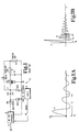
- FIG. 1 is an electrical schematic of a pulse forming network of the prior art.
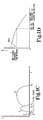
- FIG. 1A is an illustration relating ignitor gap voltage to time during lower in-cylinder pressure and air motion.
- FIG. 1B is an illustration relating ignitor gap voltage to time during higher in-cylinder pressure and air motion parameters.
- FIG. 1C is an illustration relating current to time and depicting a breakdown discharge signal, a pre-plasma discharge signal, and a main plasma discharge signal of a plasma ignition sequence.
- FIG. 1D is a graph relating the pre-plasma discharge time interval to in-cylinder pressure and charge motion.
- FIG. 1E is a block diagram for a conductive ionized channel producing system according to the present invention.
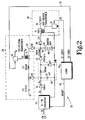
- FIG. 2 is a schematic diagram for a conductive ionized channel producing circuit according to the present invention.
- FIG. 2A is a schematic diagram of another conductive ionized channel producing circuit according to the present invention.
- FIG. 3 is an illustration relating spark breakdown voltage, sustaining voltage, pre-plasma current, and main plasma current versus time.
- FIG. 4 is a diagrammatic illustration of the layout relationship of the electrical schematics of FIGS. 6, 7, and 8.
- FIG. 5 is a diagrammatic illustration of the layout relationship of the electrical schematics of FIGS. 9, 10, 11, and 12.
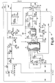
- FIGS. 6-8 are an electrical schematic of a main-plasma circuit according to the present invention.
- FIGS. 9-12 are an electrical schematic of a pre-plasma circuit according to the present invention.
- FIG. 13 is a schematic illustration of another embodiment of a plasma ignition circuit according to the present invention illustrating the interconnections between an ignitor device, the pre-plasma circuit of FIGS. 6-8, and the pre-plasma circuit of FIGS. 9-12.
- FIG. 1 an electrical schematic of a plasma ignition system 10 according to the prior art is shown in FIG. 1.
- the circuit of FIG. 1 uses a DC-DC converter 12 to convert a low voltage from signal path 14, typically 12 to 16 volts DC, into a high DC voltage required to supply current into a plasma channel. Typically the DC-DC converter voltage requirement is in the 1,000 to 3,000 volt range.
- switch SCR1 is turned on by the logic control circuit 16 to enable capacitor C10 to charge to the final DC-DC converter voltage output set point.
- switch SCR2 is turned on to apply the voltage potential of capacitor C10 to the primary of transformer T10.
- the voltage across the secondary of transformer T10 builds up in a sinusoidal wave form due to the internal capacitance of transformer T10 and the capacitance of capacitor C11.
- the auxiliary gap 24 conducts and a high potential is thereafter applied to the ignitor gap 26 of the plasma ignition system 10.
- an electrical conducting path to ground exists through the pulse shaping inductor L10, and C10 discharges the remainder of the stored charge or energy into the igniter gap as current to stimulate plasma flow.
- C10 and L10 resonate to form a damped-sine current pulse, as desired, in the plasma igniter gap.
- a disadvantage with the ignition system 10 of the prior art circuit shown in FIG. 1 is the use of costly high voltage switches to charge and discharge the energy storage capacitor C10.
- a second disadvantage is the power dissipation which occurs across the auxiliary gap 24 and in pulse transformer T10.
- capacitor C10 In order to generate a 0.150 joule pulse in the ignitor, capacitor C10 must store approximately 0.5 joules, resulting in an effective energy efficiency of 30%. The lack of efficiency is explained by the dissipation of power in the secondary of the transformer T10.
- the high turns ratio required in order to create the 1 to 100 primary to secondary ratio of transformer T10 results in a fairly high resistance in the secondary winding of transformer T10.
- capacitor C10 In order to maintain the desired plasma channel conductivity, capacitor C10 must be charged to 1,000 to 3,000 volts by the DC-DC converter 12. Therefore, the charge/fire switches, SCR1 and SCR2, must be rated to at least 3,000 volts. The capacitor C10 must also be rated to withstand at least 3,000 volts, with a 3,500 volt or more reliability rating desired. Capacitor C11, which stores energy to ensure the plasma igniter gap has sufficiently low impedance after the auxiliary gap conducts, must have a voltage rating larger than the voltage generated in the secondary of the high voltage transformer, i.e., in the range of 30 kilovolts to 40 kilovolts. A further shortcoming of the circuit of FIG. 1 is the location of auxiliary gap 24.
- the voltage at which the plasma conducts does not respond accordingly to variations in gas pressure within the cylinder or to turbocharger boost or throttle position.
- the result is wide variations in timing and a very conservative circuit must be designed to insure a plasma flow at all possible operating conditions for the engine.
- the auxiliary gap itself is subject to erosion due to the high current discharge across the gap.
- further disadvantage attributable to the auxiliary gap is the creation of large radiated E fields that must be shielded to prevent interference with other electrical systems of the vehicle and to prevent ignition hazards.
- Engines for automotive applications operate over an extremely wide range of conditions.
- the air-fuel charge motion characterized in terms of revolutions/minute or RPM
- the pressure inside the combustion chamber are significantly different than, for example, partial load cruising or full load acceleration.
- Three different sets of engine operating conditions are discussed below in relation to the requirements for an effective ignition source.
- Start-up and idle These operating conditions are characterized by relatively low in-cylinder pressure (80-150 psi) and air motion (300-900 rpm). In these conditions the breakdown discharge assumes, for example, a sinusoidal form similar to the curve A shown in FIG. 1A.
- Full load acceleration These conditions are characterized by much higher in-cylinder pressure (2415.10 3 - 3795.10 3 N/m 2 (350-550 psi)) and air motion (3000-6000 rpm). Under these conditions the breakdown discharge assumes a sinusoidal form that when compared to curve A shown in FIG. 1A, looks typically like curve B shown in FIG. 1B.
- FIG. 1C a typical plasma current discharge sequence for an apparatus according to the present invention is shown.
- the sequence includes an initial gap breakdown discharge B at time t 0 , followed by a timed pre-plasma discharge C at time t 1 and by a main plasma discharge D at time t 2 .
- the beginning of the pre-plasma discharge C is timed with respect to the start of the breakdown discharge B.
- the time interval t 1 -t 0 between these two events is varied according to the engine operating conditions to produce optimum engine performance or minimize emissions of pollutants.
- t 1 is the time at which the discharge channel has the highest conductivity and therefore is the ideal timing for pre-plasma discharge
- t 1 is not equal to t 1 ′.
- the in-cylinder pressure and charge motion values are somewhere in between the previous two cases and the value of t will be in-between t 1 and t 1 ′.
- FIG. 1D A qualitative representation of the relationship between the time interval t 1 to t 0 and the combustion chamber pressure and charge motion is shown in FIG. 1D.
- the pressure parameter increases or the charge motion parameter increases, the voltage amplitude required to sustain the breakdown discharge ringing increases and the discharge period decreases as shown in FIG. 1B.
- the value of t1 is decreased.
- the voltage required to sustain the breakdown discharge ringing is lower and the discharge period t1, is increased as shown in FIG. 1A.
- Lower pressure and slower charge motion conditions increase the time delay required between the breakdown discharge and the pre-plasma discharge for optimum engine operation is shown in FIG 1A.
- the pre-plasma discharge time interval In order to vary the pre-plasma discharge time interval in relation to different engine operating conditions, it is necessary to vary from 0 to 200 microseconds the pre-plasma discharge time interval. Preferably the time interval is varied between 25 and 50 microseconds. This may be accomplished with a simple timing logic circuit responding to variations in a single sensed engine operating condition or parameter.
- an Engine Control Unit At the opposite end of the spectrum, an Engine Control Unit (ECU) monitors various engine conditions and varies pre-plasma timing according to the engineering objective: maximize engine performance, reduction of emissions, or a combination of the two objectives. Similar technology is currently implemented to control spark timing, degree or amount of Exhaust Gas Recirculation EGR and the amount of fuel delivered for combustion in engines using conventional ignition systems.
- timing logic 44 is any circuit for varying timing logic signals, including an Engine Control Unit or computer.
- the ECU typically, all the fundamental parameters characterizing the engine operating conditions, are included in the ECU. These parameters are: intake conditions, spark advance desired, engine load, intake and exhaust temperatures, engine temperature, boost (either turbocharger or supercharger), ambient conditions and engine RPM.
- the memory of the ECU is loaded with all the functional relations between sensed engine operative conditions and engine controlling parameters (spark timing, EGR, fuel, etc.) for the pre-plasma discharge timing.
- spark timing, EGR, fuel, etc. is defined as the time after start of breakdown discharge at which the discharge kernel presents the highest conductivity.
- the ECU 44 produces timing signals to the gap breakdown circuit 28 and the pre-plasma ignition circuit 29, as a result of sensed engine and environmental signals from sensor block 27.
- Sensors 27, main plasma circuit 25 and diode D3 are shown connected by broken lines to other system components to emphasize that these components of the system are optional, as shown by the embodiment of FIG. 2A.
- the pre-plasma discharge always occurs when the breakdown discharge kernel presents the highest conductivity.
- the benefit of this method is in the capability to operate at the best consistency of discharge for any engine operative condition.
- Voltage V IN is supplied to an input to DC-DC converter 32.
- Voltage V IN is normally, in a motor vehicle, 12 volts to 16 volts DC.
- the output of DC-DC converter 32 approximately 600 Vdc, is supplied to signal path 35. This voltage is supplied to the anode of diode D1, an isolating device situated to prevent current flow from signal path 36 back into the output of DC-DC converter 32.
- the 600 volt output of DC-DC converter 32 is also supplied to capacitor C1, a one microfarad capacitor, to the primary of the high voltage transformer T1, and through diode D5 to capacitor C3, a .47 microfarad capacitor.
- the secondary winding of high voltage transformer T1 is coupled, via diode D4, to the ignitor gap 46.
- the secondary of the pre-plasma transformer is coupled to the ignitor gap 46 via diode D6.
- Capacitors C1 and C3 charge up to the 600 volt level as a result of an output voltage from DC-DC converter 32.
- Logic circuitry 44 supplies three coordinated logic signals necessary to induce the plasma flow current across ignitor gap 48 contained within engine cylinder 46 diagrammatically illustrated by broken line form.
- Signal flow path 39 hereinafter referred to as signal 39, supplies switch S1 with a logic signal to force S1 to short the primary of transformer T1 to ground, or to open the primary of transformer T1 to an open circuit condition.
- Signal path 37 hereinafter signal 37, is connected to switch S2 which opens the primary of transformer T2 to an open circuit condition, or shorts the primary of T2 to signal ground.
- Signal path 42 hereinafter signal 42, is an inhibit signal supplied to the DC-DC converter 32, to turn the output voltage signal 35 of the DC-DC converter off during the plasma event.
- the initial step in the plasma flow ignition sequence takes place when switch S1 is switched from the open to the closed position, thereby inducing a voltage increase into the secondary winding of transformer T1.
- the signal produced at the secondary of transformer T1 on signal path 52 is supplied through diode D4 to signal path 54 connected to igniter gap 48.
- the initial high voltage signal supplied from transformer T1 will result in a voltage arc or spark across igniter gap 48 once the voltage across the gap builds up to approximately 25 kilovolts.
- switch S2 is closed by logic circuit 44 thereby providing a discharge path for the energy stored in capacitor C3 through inductor L2, the primary of transformer T2, and through switch S2 to signal ground.
- the signal induced in the secondary of transformer T2 builds up to a voltage level, which exists at signal path 54 as a result of the spark voltage across the gap 48, until the voltage at signal path 50 exceeds the gap voltage, resulting in diode D6 having a forward bias voltage applied from anode to cathode.
- the pre-plasma transformer T2 converts from a voltage source to a current source and begins to supply current to the igniter gap 48 thereby inducing a pre-plasma current to flow across igniter gap 48.
- transformer T2 becomes a current transformer in operation, supplying current to the ignitor gap 48.
- the pre-plasma current flow induced at igniter gap 48 flows for approximately 40 microseconds, long enough to open a highly conductive channel across the gap.
- the current supplied by transformer T2 is described as a "pre-plasma" current signal because the current pulse precedes the main plasma signal, reducing the required voltage for the main plasma current to flow.
- a current pulse delivered through diode D6 to signal path 54 creates a conductive ionized channel between the electrodes of igniter gap 48.
- This pre-plasma current reduces the voltage necessary for the plasma flow to take place, hereafter referred to as the sustaining voltage, thereby allowing diode D3 to become forward biased as the voltage at signal path 54 now has dropped to a voltage in the area of 200 to 400 volts.
- the energy stored in capacitor C1 is discharged through inductor L1 and diode D3 to the signal path 54 thereby supplying the main plasma current to the igniter gap 48.
- Diode D2 allows circulating inductor currents after the arc is extinguished, and is rated at 1,000 volts breakdown voltage.
- Diode D4 is rated at 30 kV (Kvolts) and prevents transformer secondary current flow while the ignition coil or transformer T1 is storing energy, and during the negative voltage excursions of T1. Note that D4 can be deleted if an auxiliary gap inherent in a typical mechanical distributor-based spark system is present to isolate transformer T1 from the ignitor gap 46.
- the pulse shaping inductor L1 is connected by means of series diode D3 to the plasma igniter gap 48.
- Diode D5 allows the DC-DC converter to operate without discharging capacitor C3, while diode D6 isolates the pre-plasma circuit of transformer T1, capacitor C3, and inductor C2 from the high voltage circuit of signal path 54.
- FIG. 2A an alternate schematic illustration of a circuit 31 for producing a highly conductive channel for the flow of plasma current according to the present invention is shown.
- This circuit is identical in all respects as compared to the circuit of FIG. 2 with the differences being the elimination of inductor L1 and Diodes D2 and D3.
- diode D4 can be replaced by the auxiliary gap of a typical distributor/rotor arrangement common to most multi-cylinder internal combustion engine ignition systems thereby isolating and coupling transformer T1 to the ignitor gap.
- the embodiment shown in FIG. 2A functions similarly to the embodiment of FIG. 2 with the exception of a main plasma discharge signal supplied to the ignitor gap 46.
- a main plasma discharge signal supplied to the ignitor gap 46 By eliminating the circuitry associated with the main plasma ignition circuit shown in FIG. 1E as element 25, the device is simplified. It can be expected in certain applications of the plasma forming circuit of FIG. 2A that the plasma signal delivered from transformer T2 via diode D6 into the ignitor gap 46 will be sufficient to initiate ignition of an air-fuel mixture.
- the plasma ignition system 31 of FIG. 2A corresponds to the blocks 44, 28, 29, and 46 of FIG. 1E.
- FIG. 3 a diagrammatic illustration of the spark breakdown voltage present on signal path 52 and labeled similarly, sustaining voltage curve 60, pre-plasma current signal of signal path 50, and main plasma current signal of signal path 54 are graphically related versus time.
- the required voltage for initiating plasma flow i.e. the sustaining voltage
- the spark breakdown voltage signal 52 drops from 25,000 to approximately 500-3,000 volts indicating that a voltage spark exists across the ignitor gap electrodes.
- the time delay from time line 53 to the beginning of the pre-plasma current flow at 57 is determined by various factors which affect the spark breakdown voltage, such as cylinder pressure, cylinder temperature, and the size of the ignitor gap.
- the pre-plasma current 50 is delayed until after the time which is the theoretical maximum possible delay which can occur prior to the spark breakdown voltage dropping from 25,000 to approximately 500-3,000 volts.
- the short duration, approximately 40-50 microseconds, pre-plasma current pulse flows across the igniter gap 48 in the ionized channel created by the voltage spark.
- the pre-plasma current flow creates a low impedance conducting channel across the igniter gap.
- the sustaining voltage across the gap is reduced to a consistent value of approximately 200-400 volts.
- the sustaining voltage of 400 volts is less than the main plasma voltage of 600 volts present on capacitor C1, the main plasma current flows in the channel from the energy stored in capacitor C1 of FIG. 2.
- the required main plasma voltage is reduced from 3,000 volts to less than 600 volts without loss of performance.
- the volt-second capability of transformer T2 is reduced because voltage is not applied to the primary of T2 while the spark voltage is being created and stabilized.
- cost advantages and size reductions are gained with respect to transformer T2.
- the volt-seconds capability of transformer T2 is directly related to flux storage capability of the transformer, which in turn directly impacts transformer winding and core size.
- the circuits of FIG. 2 and FIG. 2A can be used with a multi-cylinder engine.
- a distributor device inserted into the circuit between the circuit junction of diodes D3, D4 and D6, and ignitor gap 48 provides distribution of the plasma ignition signal to all ignitor gap devices.
- a typical 4-cylinder 4-stroke engine operating at 3,000 RPM requires a 50 hertz firing signal. Frequency of firing directly affects the power requirements of the DC-DC converter 32 and dictates whether a single plasma ignition circuit coupled with a distributor verses individual plasma ignition circuits is more cost effective in a particular engine configuration.
- charge time of capacitors C1 and C3 is approximately 5-7 milliseconds if a DC-DC converter of approximately 15W output capability is used.
- the embodiment of the invention shown in FIG. 2 circumvents the problem of producing a high current, high voltage signal from the same transformer.
- the circuit instead employs two separate transformers, one producing the high voltage electrode gap breakdown voltage, the second transformer T2 producing the pre-plasma current signal.
- two different transformers By using two different transformers, the need for both a large number of turns for high voltage, and large gauge for sufficient current for a low impedance plasma channel in a single device is eliminated.
- the volume of transformer T2 will increase linearly with the period of time required to sustain a 3,000 volt signal across the ignitor gap. This is best described by relating the volt-second capability of the transformer to the volume of the transformer.
- the embodiment of the invention reduces the volt-seconds requirements for transformer T2 by delaying the application of voltage to the primary of T2 until after the electrode gap breakdown has occurred. This is accomplished by the S2 logic 37 which delays turn on of S2 until a preset period of time has elapsed from S1 turning on. By delaying logic S2 for this interval, the total time, and thus the total volt-seconds required of transformer T2 is reduced.
- the pre-plasma transformer circuit also extends ignitor gap or spark plug life as opposed to the prior art circuits for plasma ignition using a capacitor as the primary power storage device for initiating plasma flow.
- An inhibit signal supplied by way of signal path 42 to an input of DC-DC converter 32 provides a logic control signal to converter 32 inhibiting the output of the converter 32 during the period that capacitor C1 is discharging the stored energy through conductor L1 and diode D3 into the ignitor gap 48.
- the purpose behind inhibiting the converter 32 is to protect the output driver devices of converter 32 from attempting to maintain the converter output voltage at a 600 volt level at a point in time when the load seen by the output of the converter 32 is a low impedance. If the output of converter 32 were not inhibited, the converter 32 would attempt to maintain the output at signal path 35 at 600 volts at all times.
- the converter 32 will attempt to supply additional current in order to raise its output voltage to 600 volts, thereby resulting in a strong likelihood of a continuous plasma flow with subsequent damage to the output driver devices within converter 32, and premature erosion of the electrodes.
- FIGS. 6-13 Another embodiment of a circuit 100 (see FIG. 13) for generating a highly conductive channel for the flow of plasma current according to the present invention is shown in FIGS. 6-13.
- FIGS. 6, 7, and 8 may be positioned according to the diagram in FIG. 4 in order to view the entire circuit 110 for producing main plasma flow.
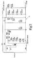
- FIG. 5 diagrams the arrangement of FIGS. 9, 10, 11, and 12, which together show a circuit schematic for the pre-plasma circuitry 120.
- the circuitry shown in FIGS. 6, 7, and 8 comprises the main-plasma circuit 110 and is a completely separate and independent circuit from the circuitry for the pre-plasma circuit 120 shown in FIGS. 9-12. Symbols used for components of the circuitry of FIGS.
- R1 for a resistor may appear more than once in FIGS. 6-12, however each use of “R1” refers to a new component if used in a different figure.
- Component values, tolerances, IC part numbers, and voltage ratings are indicated on the schematics of FIGS. 6-12 in close proximity to the corresponding circuit component.
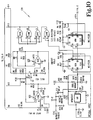
- FIGS. 6, 7, and 8 an electrical schematic for the main-plasma circuit 110 according to the invention is shown.
- DC input power for the circuit is supplied at connections J1-5 and J1-6 of FIG. 6.
- Main-plasma output current is supplied to an ignitor gap, shown in FIG. 13, from connection J1-11 of FIG. 7.
- Connection J1-7 provides a return path for the main-plasma output signal produced at connection J1-11 of FIG. 7.
- DC input power is regulated by device Q1 and the associated passive component circuitry connected with Q1.
- the regulated DC voltage is supplied to pin 15 of device U1, a DC-DC converter controller IC.
- Transformer T1 and integrated circuits U2A, U3A, U3B, and Q2 and the associated passive components connected to these devices comprise the DC-DC converter circuitry for producing 600 volts DC at the junction of inductor L3 and capacitor C13 of FIG. 7.
- the main-plasma output signal at connection J1-11 is connected to input pin 5 of monostable multivibrator device U5A through resistor R18 in FIG. 8.
- Device U5A provides an inhibit output signal to the input of OR gate U4D.
- the buffer device U4D is connected to the inputs of devices U4A, U4B, and U4C.
- Parallel output connections of OR gates U4A, U4B and U4C provide sufficient current drive capability, CMOS to an input pin 10 of device U1 to inhibit the output of device U1 in FIG. 6.
- Resistor R16 and capacitor C9 connected to device U5A control the width of the inhibit pulse produced at the output pin 6 of device U5A in FIG. 8.
- the positive pulse produced at output pin 6 of U5A will be approximately 470 microseconds.
- the pulse produced at output pin 6 of device USA will inhibit the DC-DC converter output signal for 470 microseconds, the period of time corresponding to the maximum duration of current flow from connection J1-11 of FIG. 7 to the ignitor gap 126 of FIG. 13.
- the main-plasma circuit of FIGS. 6-8 provides a source of current for main plasma flow in the ignitor gap 126 of FIG. 13 once a highly conductive ionized channel has been created across the ignitor gap 126 of FIG. 13.
- the falling-edge-triggered input pin 5 of device U5A in FIG. 8 is triggered disabling the DC-DC converter at U1 of FIG. 6 for the 470 microseconds as determined by capacitor C9 and resistor R16 of FIG. 8.
- output pin 6 of device U5A in FIG. 8 will again fall low thereby enabling the output of DC-DC converter controller U1 in FIG. 6 and thus recharging storage capacitors C11 and C13..
- a pre-plasma circuit 120 according to the invention is shown.
- DC power is supplied to the pre-plasma circuit board at connections J1-5 and J1-6 of FIG. 9, with the positive voltage at J1-5 and the signal ground or DC input return at connection J1-6.
- Device Q1 and the passive components connected to it provide a voltage regulation function for the voltage VCC.
- a DC-DC converter circuit for producing a high DC output voltage from the low DC input voltage supplied to connection J1-5 of FIG. 9 is comprised of the following active devices and associated passive components connected thereto: U1, U2A, Q2 of FIG. 11, U3A and U3B of FIG. 10, and transformer T1 of FIG. 11.
- Regulated DC voltage from device Q1 is supplied to input pin 15 of device U1, a DC-DC converter controller IC.
- the 600 volt output is isolated by diodes CR6, CR7, and CR8, and is supplied to capacitor C11 a charge storage device and through CR11 and CR12 to capacitor C13, a charge storage device.
- An input trigger signal will initiate a pulse output from the non-retriggerable monostable multivibrator device USA in FIG. 10.
- the pulse signal produced at the output of device USA at pins 6 and 7 is a 470 microseconds pulse which inhibits the output of device U1 of FIG. 9 through buffer devices U4A, U4B, U4C and U4D, thereby preventing any harm to the DC-DC converter circuit while the plasma flow sequence is in process.
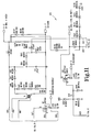
- a second non-retriggerable monostable multivibrator U5B is triggered and a low-going pulse is produced at pin 9 of device U5B in FIG. 10, thereby triggering device U2B in FIG. 12 and Q3 of FIG. 11 to turn on thereby immediately initiating current flow through the primary coil of a high voltage transformer connected to connection J1-9 of FIG. 11 as illustrated in FIG. 13, by transformer T5.
- the low-going pulse at U5B pin 9 of FIG. 10 is 123-423 microseconds in duration.
- the closing of the primary of transformer T5 in FIG. 13 produces a high voltage signal in the secondary winding of T5 as capacitors C11 and C13 discharge through transformer T5.
- the high voltage signal is supplied to the anode of diode 123 and thereafter appears at ignitor gap 126.
- the primary of transformer T5 in FIG. 13 is connected to ground through connection J1-9 of the pre-plasma circuit 120 for a period determined by capacitor C14 and resistor R33 of FIG. 10, or approximately 123 to 423 microseconds.
- An output signal from device U2B, an FET driver device also supplies an input signal to the positive-edge-triggered input pin 4 of device U6A of FIG. 12.
- Device U6A provides an 18 to 62 microsecond signal delay prior to activation of the pre-plasma multivibrator timer device U5B. As the output pin 6 of U6A of FIG.
- connection TP-1 a high voltage connection wired directly to the pre-plasma circuit 120 to the ignitor gap 126.
- the signal provided by transformer T2 of FIG. 12 acts to stabilize the plasma sustaining voltage for creating a highly conductive ionized channel across the ignitor gap 126 of FIG. 13.
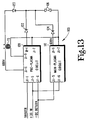
- FIG. 13 a schematic illustration of the interconnections between the pre-plasma circuit 120 of FIGS. 9-12 and the main-plasma circuit 110 of FIGS. 6-8 is shown.
- Both the pre-plasma circuit 120 and the main-plasma circuit 110 share a common DC power supply signal supplied to input connections J1-5 and J1-6 of circuits 120 and 110.
- a trigger signal for initiating plasma ignition is provided to input J1-1 of pre-plasma circuit 120.
- the primary of a high voltage transformer T5 is connected to connections J1-11 and J1-9 of the preplasma circuit 120.
- the output or secondary of high voltage transformer T5 is connected to a high voltage summing diode 123 and to signal ground at connections J1-7 of circuits 110 and 120.
- the pre-plasma output signal supplied to connection TP-1 of circuit 120 is supplied through summing diode 122 to the ignitor gap 126.
- the main-plasma circuit output signal found at connection J1-11 is supplied through summing diode 124 to ignitor gap 126.
- FIGS. 6-12 can be combined into a single high voltage supply.
- Those skilled in the art will also recognize that other methods of coupling the main plasma 112 and the pre-plasma 110 of FIG. 13 to the ignitor 126 are readily apparent, such as a tapped diode or suitable spark gaps.
- a conventional flyback high voltage ignition circuit as found in most automotive engine ignition systems can substitute for the capacitive discharge high voltage circuits shown in FIGS. 2, 2A and 6-12 used to produce a high voltage spark across the ignitor gap of the embodiment shown.
Landscapes
- Engineering & Computer Science (AREA)
- Physics & Mathematics (AREA)
- Plasma & Fusion (AREA)
- Chemical & Material Sciences (AREA)
- Combustion & Propulsion (AREA)
- Mechanical Engineering (AREA)
- General Engineering & Computer Science (AREA)
- Ignition Installations For Internal Combustion Engines (AREA)
Claims (18)
- Procédé pour créer un canal ionisé hautement conducteur pour l'écoulement d'un courant de plasma entre deux électrodes, induisant de ce fait une combustion d'un mélange air-combustible dans un moteur, le procédé comprenant les étapes consistant à :a) envoyer un signal à haute tension à une première électrode pour induire un claquage dans une seconde électrode;b) attendre pendant un temps de retard prédéterminé;c) envoyer un signal préalable de plasma à haute tension, à courant intense et de brève durée à ladite première électrode pour dilater ledit canal ionisé conducteur et réduire la résistance dudit canal; etd) envoyer un signal principal de plasma à basse tension et à courant intense à ladite première électrode pour induire un écoulement de plasma principal entre lesdites électrodes.
- Procédé selon la revendication 1, selon lequel ledit retard prédéterminé est modifié en fonction de variations d'une condition détectée de fonctionnement du moteur.
- Procédé selon la revendication 2, selon lequel ladite condition détectée de fonctionnement du moteur est la vitesse de rotation dudit moteur.
- Procédé selon la revendication 2, selon lequel ladite condition détectée de fonctionnement du moteur est une dépression dans le moteur.
- Procédé selon la revendication 2, selon lequel ladite condition détectée de fonctionnement du moteur est une température dudit moteur
- Procédé selon la revendication 2, selon lequel ladite condition détectée de fonctionnement du moteur est la charge appliquée audit moteur.
- Dispositif d'allumage à écoulement de plasma (30) comprenant :un dispositif d'allumage (48) possédant des première et seconde électrodes;des premiers moyens formant circuit (28) connectés audit dispositif d'allumage pour appliquer un signal à haute tension à ladite première électrode et induire une étincelle à haute tension entre lesdites électrodes;des seconds moyens formant circuits (29,120) connectés audit dispositif d'allumage pour envoyer un signal de sortie impulsionnel préalable de courant de plasma à ladite première électrode et envoyer une tension de maintien de l'écoulement de plasma auxdites électrodes;des moyens (44) de commande de cadencement connectés auxdits premiers et seconds moyens formant circuits pour permettre un retard prédéterminé du signal de sortie impulsionnel préalable de courant de plasma après l'apparition de ladite étincelle à haute tension entre lesdites électrodes; etdes moyens d'alimentation en énergie (32) pour appliquer une énergie auxdits premiers moyens formant circuit et auxdits seconds moyens formant circuit.
- Dispositif d'allumage à écoulement de plasma selon la revendication 7, comprenant en outre :des troisièmes moyens formant circuit (25) connectés à ladite première électrode et auxdits moyens d'alimentation en énergie pour appliquer un courant à ladite première électrode pour produire un écoulement principal de plasma entre lesdites électrodes après que lesdits seconds moyens formant circuit ont envoyé ledit signal de sortie impulsionnel préalable de courant de plasma auxdites électrodes; etdans lequel ledit retard prédéterminé est modifié en fonction de conditions de fonctionnement du moteur.
- Dispositif d'allumage à écoulement de plasma selon la revendication 7 ou 8, dans lequel lesdits premiers moyens formant circuit (28) comprennent un transformateur à haute tension (T1) possédant un enroulement primaire et un enroulement secondaire, ledit enroulement primaire étant connecté auxdits moyens d'alimentation en énergie au niveau d'un premier conducteur (36), et des moyens de commutation électrique (S1) étant connectés entre un second conducteur dudit enroulement primaire et un potentiel de masse du signal, lesdits conducteurs de l'enroulement secondaire dudit transformateur à haute tension étant couplés respectivement à ladite première électrode et à la masse.
- Dispositif d'allumage à écoulement de plasma selon l'une quelconque des revendications 7-9, dans lequel lesdits seconds moyens formant circuit (29,120) comprennent un transformateur (T2) possédant un enroulement primaire et un enroulement secondaire, ledit enroulement primaire dudit transformateur étant connecté auxdits moyens d'alimentation en énergie au niveau d'un premier conducteur, et à des moyens de commutation de masse (S2) au niveau d'un second conducteur, ledit enroulement secondaire dudit transformateur étant couplé à ladite première électrode et à ladite masse du signal.
- Dispositif d'allumage à écoulement de plasma selon l'une quelconque des revendications 7-10, dans lequel lesdits moyens de commande de cadencement (44) sont une unité de commande du moteur, comprenant des moyens pour détecter la vitesse du moteur et modifier ledit retard prédéterminé en rapport avec la vitesse détectée du moteur.
- Dispositif d'allumage à écoulement de plasma selon l'une quelconque des revendications 7-10, dans lequel lesdits moyens de commande de cadencement (44) sont une unité de commande du moteur comprenant des moyens pour détecter les conditions de charge du moteur et modifier ledit retard prédéterminé en rapport avec la charge détectée du moteur.
- Dispositif d'allumage à écoulement de plasma selon l'une quelconque des revendications 7-10, dans lequel lesdits moyens de commande de cadencement (44) sont une unité de commande du moteur comprenant des moyens pour détecter des conditions ambiantes et modifier ledit retard prédéterminé en rapport avec des conditions ambiantes détectées.
- Dispositif d'allumage à écoulement de plasma selon l'une quelconque des revendications 7-13, dans lequel les moyens d'alimentation en énergie (32) sont un convertisseur continu-continu.
- Dispositif d'allumage à écoulement de plasma selon la revendication 14, comprenant des moyens de stockage de charges, connectés en parallèle avec la sortie desdits moyens formant convertisseur continu-continu, et des moyens formant circuit d'inhibition pour inhiber le signal de sortie dudit convertisseur continu-continu lorsque ledit signal préalable de courant de plasma et ledit signal principal de courant de plasma sont envoyés à ladite première électrode.
- Dispositif d'allumage à écoulement de plasma selon la revendication 8 comprenant des moyens redresseurs intercalés entre la sortie desdits premiers moyens formant circuit et ladite première électrode.
- Dispositif d'allumage à écoulement de plasma selon la revendication 16, dans lequel lesdits moyens redresseurs sont des diodes à haute tension.
- Dispositif d'allumage à écoulement de plasma selon la revendication 8 comprenant des moyens formant entrefer auxiliaire intercalés entre la sortie desdits premiers moyens formant circuit et ladite première électrode.
Applications Claiming Priority (2)
| Application Number | Priority Date | Filing Date | Title |
|---|---|---|---|
| US07/440,027 US4996967A (en) | 1989-11-21 | 1989-11-21 | Apparatus and method for generating a highly conductive channel for the flow of plasma current |
| US440027 | 1989-11-21 |
Publications (3)
| Publication Number | Publication Date |
|---|---|
| EP0434217A2 EP0434217A2 (fr) | 1991-06-26 |
| EP0434217A3 EP0434217A3 (en) | 1992-03-18 |
| EP0434217B1 true EP0434217B1 (fr) | 1997-01-08 |
Family
ID=23747128
Family Applications (1)
| Application Number | Title | Priority Date | Filing Date |
|---|---|---|---|
| EP90312615A Expired - Lifetime EP0434217B1 (fr) | 1989-11-21 | 1990-11-20 | Installation d'allumage par plasma |
Country Status (4)
| Country | Link |
|---|---|
| US (1) | US4996967A (fr) |
| EP (1) | EP0434217B1 (fr) |
| JP (1) | JP2532743B2 (fr) |
| DE (1) | DE69029649T2 (fr) |
Cited By (1)
| Publication number | Priority date | Publication date | Assignee | Title |
|---|---|---|---|---|
| RU2461730C2 (ru) * | 2007-06-12 | 2012-09-20 | Рено С.А.С. | Диагностика состояния загрязнения свечей системы радиочастотного зажигания |
Families Citing this family (45)
| Publication number | Priority date | Publication date | Assignee | Title |
|---|---|---|---|---|
| GB9124824D0 (en) * | 1991-11-22 | 1992-01-15 | Ortech Corp | Plasma-arc ignition system |
| US5211152A (en) * | 1992-01-21 | 1993-05-18 | Felix Alexandrov | Distributorless ignition system |
| US5587630A (en) * | 1993-10-28 | 1996-12-24 | Pratt & Whitney Canada Inc. | Continuous plasma ignition system |
| US5558071A (en) * | 1994-03-07 | 1996-09-24 | Combustion Electromagnetics, Inc. | Ignition system power converter and controller |
| US5568801A (en) * | 1994-05-20 | 1996-10-29 | Ortech Corporation | Plasma arc ignition system |
| US5555862A (en) * | 1994-07-19 | 1996-09-17 | Cummins Engine Company, Inc. | Spark plug including magnetic field producing means for generating a variable length arc |
| US5619959A (en) * | 1994-07-19 | 1997-04-15 | Cummins Engine Company, Inc. | Spark plug including magnetic field producing means for generating a variable length arc |
| US5529046A (en) * | 1995-01-06 | 1996-06-25 | Xerox Corporation | High voltage ignition control apparatus for an internal combustion engine |
| US5704321A (en) * | 1996-05-29 | 1998-01-06 | The Trustees Of Princeton University | Traveling spark ignition system |
| US5793585A (en) * | 1996-12-16 | 1998-08-11 | Cowan; Thomas L. | Ignitor circuit enhancement |
| US6131555A (en) * | 1998-04-20 | 2000-10-17 | Cummins Engine Company, Inc. | System for controlling ignition energy of an internal combustion engine |
| US6035838A (en) * | 1998-04-20 | 2000-03-14 | Cummins Engine Company, Inc. | Controlled energy ignition system for an internal combustion engine |
| MXPA01013285A (es) | 1999-06-16 | 2002-12-13 | Knite Inc | Sistema de encendido de modo dual que utiliza dispositivo de encendido de chispa de desplazamiento. |
| GB2352772A (en) * | 1999-08-05 | 2001-02-07 | Ford Global Tech Inc | Method of operating a spark-ignition i.c. engine using a series of sparks to promote auto-ignition |
| TW505733B (en) | 1999-09-15 | 2002-10-11 | Knite Inc | Electronic circuits for plasma generating devices |
| US6474321B1 (en) | 1999-09-15 | 2002-11-05 | Knite, Inc. | Long-life traveling spark ignitor and associated firing circuitry |
| US6637393B2 (en) | 2002-01-24 | 2003-10-28 | General Motors Corporation | HCCI engine combustion control apparatus and method |
| US6883507B2 (en) * | 2003-01-06 | 2005-04-26 | Etatech, Inc. | System and method for generating and sustaining a corona electric discharge for igniting a combustible gaseous mixture |
| WO2006113850A1 (fr) | 2005-04-19 | 2006-10-26 | Knite, Inc. | Procede et appareil pour le fonctionnement d'allumeur a etincelle mobile a haute pression |
| US7398758B2 (en) * | 2005-10-25 | 2008-07-15 | Gm Global Technology Operations, Inc. | Combustion control method for a direct-injection controlled auto-ignition combustion engine |
| FR2895169B1 (fr) | 2005-12-15 | 2008-08-01 | Renault Sas | Optimisation de la frequence d'excitation d'un resonateur |
| JP2007285162A (ja) * | 2006-04-13 | 2007-11-01 | Toyota Motor Corp | 内燃機関の点火制御装置 |
| BRPI0601626C1 (pt) * | 2006-05-08 | 2009-11-24 | Vivaldo Mazon | sistema de ignição contìnua para motor a combustão interna por meio de plasma |
| JP4803008B2 (ja) * | 2006-12-05 | 2011-10-26 | 株式会社デンソー | 内燃機関の点火制御装置 |
| JP5082530B2 (ja) * | 2007-03-23 | 2012-11-28 | 日産自動車株式会社 | エンジン点火制御装置 |
| JP2009097500A (ja) * | 2007-09-26 | 2009-05-07 | Denso Corp | プラズマ式点火装置 |
| JPWO2009088045A1 (ja) * | 2008-01-08 | 2011-05-26 | 日本特殊陶業株式会社 | プラズマ点火プラグの点火制御システム及び点火制御方法 |
| FR2927482B1 (fr) * | 2008-02-07 | 2010-03-05 | Renault Sas | Dispositif de generation de haute tension. |
| FR2932229B1 (fr) * | 2008-06-05 | 2011-06-24 | Renault Sas | Pilotage de l'alimentation electrique d'une bougie d'allumage d'un moteur a combustion interne |
| JP2010144592A (ja) * | 2008-12-18 | 2010-07-01 | Hitachi Automotive Systems Ltd | 内燃機関の点火制御装置,制御方法および点火装置 |
| JP5158055B2 (ja) * | 2009-02-19 | 2013-03-06 | 株式会社デンソー | プラズマ式点火装置 |
| US8555867B2 (en) * | 2009-06-18 | 2013-10-15 | Arvind Srinivasan | Energy efficient plasma generation |
| JP5658872B2 (ja) * | 2009-11-09 | 2015-01-28 | ダイハツ工業株式会社 | 火花点火式内燃機関の点火装置 |
| JP4975132B2 (ja) * | 2010-04-02 | 2012-07-11 | 三菱電機株式会社 | プラズマ式点火装置 |
| CN102023153B (zh) * | 2010-10-20 | 2011-12-28 | 无锡市金义博仪器科技有限公司 | 光电直读光谱仪激发光源 |
| JP5351874B2 (ja) | 2010-11-25 | 2013-11-27 | 日本特殊陶業株式会社 | プラズマ点火装置およびプラズマ点火方法 |
| US9909552B2 (en) | 2011-07-16 | 2018-03-06 | Imagineering, Inc. | Plasma generating device, and internal combustion engine |
| EP2737201A1 (fr) | 2011-07-26 | 2014-06-04 | Knite, Inc. | Allumeur à étincelle circulante |
| EP2743497A4 (fr) * | 2011-08-10 | 2016-07-27 | Imagineering Inc | Moteur à combustion interne |
| DE202012004602U1 (de) * | 2012-05-08 | 2013-08-12 | Rosenberger Hochfrequenztechnik Gmbh & Co. Kg | Hochfrequenz-Plasmazündvorrichtung |
| EP2935866B8 (fr) | 2012-12-21 | 2019-05-22 | Federal-Mogul Ignition LLC | Stratégie de commande intra-événement pour systèmes d'allumage à effet corona |
| RU2565777C2 (ru) * | 2013-10-03 | 2015-10-20 | Федеральное государственное бюджетное образовательное учреждение высшего профессионального образования "Южно-Уральский государственный университет" (национальный исследовательский университет) (ФГБОУ ВПО "ЮУрГУ" (НИУ)) | Система зажигания для двс с увеличенной энергией разряда |
| DE102013112039B4 (de) * | 2013-10-31 | 2015-05-07 | Borgwarner Ludwigsburg Gmbh | Korona-Zündsystem für einen Verbrennungsmotor und Verfahren zur Steuerung eines Korona-Zündsystems |
| US10066593B2 (en) * | 2017-01-30 | 2018-09-04 | Marshall Electric Corp. | Electronic spark timing control system for an AC ignition system |
| US10082123B2 (en) * | 2017-01-30 | 2018-09-25 | Marshall Electric Corp. | Electronic spark timing control system for an AC ignition system |
Family Cites Families (32)
| Publication number | Priority date | Publication date | Assignee | Title |
|---|---|---|---|---|
| GB1410471A (en) * | 1971-11-16 | 1975-10-15 | Ass Eng Ltd | Ignition devices |
| US3842818A (en) * | 1972-11-16 | 1974-10-22 | Ass Eng Ltd | Ignition devices |
| US4029072A (en) * | 1973-08-27 | 1977-06-14 | Toyota Jidosha Kogyo Kabushiki Kaisha | Igniting apparatus for internal combustion engines |
| DE2606890C2 (de) * | 1976-02-20 | 1985-11-07 | Robert Bosch Gmbh, 7000 Stuttgart | Hochleistungszündanlage für Brennkraftmaschinen |
| US4122816A (en) * | 1976-04-01 | 1978-10-31 | The United States Of America As Represented By The Administrator Of The National Aeronautics And Space Administration | Plasma igniter for internal combustion engine |
| US4317068A (en) * | 1979-10-01 | 1982-02-23 | Combustion Electromagnetics, Inc. | Plasma jet ignition system |
| US4369756A (en) * | 1980-01-11 | 1983-01-25 | Nissan Motor Co., Ltd. | Plasma jet ignition system for internal combustion engine |
| JPS5720555A (en) * | 1980-07-10 | 1982-02-03 | Nippon Soken Inc | Igniter for internal combustion engine |
| JPS5732069A (en) * | 1980-07-31 | 1982-02-20 | Nissan Motor Co Ltd | Igniter for internal combustion engine |
| JPS5756667A (en) * | 1980-09-18 | 1982-04-05 | Nissan Motor Co Ltd | Plasma igniter |
| JPS5756668A (en) * | 1980-09-18 | 1982-04-05 | Nissan Motor Co Ltd | Plasma igniter |
| JPS6055711B2 (ja) * | 1981-01-08 | 1985-12-06 | 日産自動車株式会社 | プラズマ点火装置 |
| JPS57140567A (en) * | 1981-02-23 | 1982-08-31 | Nissan Motor Co Ltd | Plasma ignition device for internal combustion engine |
| JPS57165673A (en) * | 1981-04-07 | 1982-10-12 | Nissan Motor Co Ltd | Plasma ignition device |
| US4345575A (en) * | 1981-05-20 | 1982-08-24 | Jorgensen Adam A | Ignition system with power boosting arrangement |
| JPS57203867A (en) * | 1981-06-09 | 1982-12-14 | Nissan Motor Co Ltd | Plasma ignition apparatus |
| JPS57198372U (fr) * | 1981-06-12 | 1982-12-16 | ||
| JPS57206776A (en) * | 1981-06-16 | 1982-12-18 | Nissan Motor Co Ltd | Plasma ignition device |
| JPS5835268A (ja) * | 1981-08-27 | 1983-03-01 | Nissan Motor Co Ltd | デイ−ゼルエンジン始動用点火装置 |
| JPS5859376A (ja) * | 1981-10-05 | 1983-04-08 | Nissan Motor Co Ltd | プラズマ点火装置 |
| JPS58162718A (ja) * | 1982-03-23 | 1983-09-27 | Nissan Motor Co Ltd | ディーゼルエンジン始動用点火装置 |
| JPS595791A (ja) * | 1982-07-01 | 1984-01-12 | Sony Corp | Catvシステム |
| JPS59224474A (ja) * | 1983-04-04 | 1984-12-17 | Hitachi Ltd | エンジンの点火装置 |
| JPS60551A (ja) * | 1983-06-16 | 1985-01-05 | Hitachi Ltd | 自動車用データ伝送システム |
| US4562823A (en) * | 1983-07-15 | 1986-01-07 | Nippon Soken, Inc. | Ignition device for internal combustion engine |
| US4471732A (en) * | 1983-07-20 | 1984-09-18 | Luigi Tozzi | Plasma jet ignition apparatus |
| JPS6060270A (ja) * | 1983-09-09 | 1985-04-06 | Hitachi Ltd | 高エネルギ点火装置 |
| JPS6098168A (ja) * | 1983-11-04 | 1985-06-01 | Mitsubishi Electric Corp | プラズマ点火装置 |
| DE3342723C2 (de) * | 1983-11-25 | 1986-07-03 | Gunter Dipl.-Phys. Dr. 7500 Karlsruhe Hartig | Zündeinrichtung für Brennkraftmaschinen |
| JPS60237164A (ja) * | 1984-05-09 | 1985-11-26 | Mitsubishi Electric Corp | 点火装置 |
| US4774914A (en) * | 1985-09-24 | 1988-10-04 | Combustion Electromagnetics, Inc. | Electromagnetic ignition--an ignition system producing a large size and intense capacitive and inductive spark with an intense electromagnetic field feeding the spark |
| EP0228840B1 (fr) * | 1986-01-07 | 1991-07-17 | LUCAS INDUSTRIES public limited company | Circuit générateur d'impulsion pour système d'allumage |
-
1989
- 1989-11-21 US US07/440,027 patent/US4996967A/en not_active Expired - Lifetime
-
1990
- 1990-11-20 EP EP90312615A patent/EP0434217B1/fr not_active Expired - Lifetime
- 1990-11-20 DE DE69029649T patent/DE69029649T2/de not_active Expired - Fee Related
- 1990-11-21 JP JP2317586A patent/JP2532743B2/ja not_active Expired - Fee Related
Cited By (1)
| Publication number | Priority date | Publication date | Assignee | Title |
|---|---|---|---|---|
| RU2461730C2 (ru) * | 2007-06-12 | 2012-09-20 | Рено С.А.С. | Диагностика состояния загрязнения свечей системы радиочастотного зажигания |
Also Published As
| Publication number | Publication date |
|---|---|
| DE69029649D1 (de) | 1997-02-20 |
| EP0434217A3 (en) | 1992-03-18 |
| EP0434217A2 (fr) | 1991-06-26 |
| JPH03264772A (ja) | 1991-11-26 |
| DE69029649T2 (de) | 1997-05-07 |
| JP2532743B2 (ja) | 1996-09-11 |
| US4996967A (en) | 1991-03-05 |
Similar Documents
| Publication | Publication Date | Title |
|---|---|---|
| EP0434217B1 (fr) | Installation d'allumage par plasma | |
| US6112730A (en) | Ignition system with clamping circuit for use in an internal combustion engine | |
| EP0482127B1 (fr) | Dispositif d'allumage pour moteur a combustion interne | |
| US5568801A (en) | Plasma arc ignition system | |
| US4487177A (en) | Apparatus and method for starting a diesel engine using plasma ignition plugs | |
| JP2000170632A (ja) | 点火装置 | |
| GB2085076A (en) | Plasma ignition system | |
| CA2094509A1 (fr) | Circuit electrique | |
| JPH0135177B2 (fr) | ||
| JPS618470A (ja) | 内燃機関の燃料−空気混合物の燃焼開始方法及びその装置 | |
| JP2597126B2 (ja) | 内燃機関の点火火花を発生する方法および装置 | |
| US5806504A (en) | Hybrid ignition circuit for an internal combustion engine | |
| US4487192A (en) | Plasma jet ignition system | |
| US6670777B1 (en) | Ignition system and method | |
| US9784232B1 (en) | Forced frequency ignition system for an internal combustion engine | |
| JPS5823281A (ja) | 内燃機関の点火装置 | |
| EP0463800B1 (fr) | Système d'allumage à courant continu | |
| US6135099A (en) | Ignition system for an internal combustion engine | |
| JP6095819B1 (ja) | 高周波放電点火装置 | |
| EP0628719B1 (fr) | Dispositif d'allumage avec un circuit de déclenchement automatique d'une décharge de condensateur à basse tension | |
| JPS5825581A (ja) | プラズマ点火装置 | |
| US4149509A (en) | Breakerless ignition system | |
| Mon | Capacitive Discharge Ignition CDI System for Spark Ignition SI Engine Pulse Control Circuit | |
| JP4968203B2 (ja) | プラズマ式点火装置 | |
| JPH0531667B2 (fr) |
Legal Events
| Date | Code | Title | Description |
|---|---|---|---|
| PUAI | Public reference made under article 153(3) epc to a published international application that has entered the european phase |
Free format text: ORIGINAL CODE: 0009012 |
|
| AK | Designated contracting states |
Kind code of ref document: A2 Designated state(s): DE GB |
|
| PUAL | Search report despatched |
Free format text: ORIGINAL CODE: 0009013 |
|
| AK | Designated contracting states |
Kind code of ref document: A3 Designated state(s): DE GB |
|
| 17P | Request for examination filed |
Effective date: 19920818 |
|
| 17Q | First examination report despatched |
Effective date: 19950529 |
|
| GRAG | Despatch of communication of intention to grant |
Free format text: ORIGINAL CODE: EPIDOS AGRA |
|
| GRAH | Despatch of communication of intention to grant a patent |
Free format text: ORIGINAL CODE: EPIDOS IGRA |
|
| GRAH | Despatch of communication of intention to grant a patent |
Free format text: ORIGINAL CODE: EPIDOS IGRA |
|
| GRAA | (expected) grant |
Free format text: ORIGINAL CODE: 0009210 |
|
| STAA | Information on the status of an ep patent application or granted ep patent |
Free format text: STATUS: THE PATENT HAS BEEN GRANTED |
|
| AK | Designated contracting states |
Kind code of ref document: B1 Designated state(s): DE GB |
|
| REF | Corresponds to: |
Ref document number: 69029649 Country of ref document: DE Date of ref document: 19970220 |
|
| PGFP | Annual fee paid to national office [announced via postgrant information from national office to epo] |
Ref country code: GB Payment date: 19971027 Year of fee payment: 8 |
|
| PLBE | No opposition filed within time limit |
Free format text: ORIGINAL CODE: 0009261 |
|
| 26N | No opposition filed | ||
| PG25 | Lapsed in a contracting state [announced via postgrant information from national office to epo] |
Ref country code: GB Free format text: LAPSE BECAUSE OF NON-PAYMENT OF DUE FEES Effective date: 19981120 |
|
| GBPC | Gb: european patent ceased through non-payment of renewal fee |
Effective date: 19981120 |
|
| PGFP | Annual fee paid to national office [announced via postgrant information from national office to epo] |
Ref country code: DE Payment date: 20031231 Year of fee payment: 14 |
|
| PG25 | Lapsed in a contracting state [announced via postgrant information from national office to epo] |
Ref country code: DE Free format text: LAPSE BECAUSE OF NON-PAYMENT OF DUE FEES Effective date: 20050601 |