EP0433554A1 - Brûleur pour la combustion de combustibles liquides ou gazeux - Google Patents
Brûleur pour la combustion de combustibles liquides ou gazeux Download PDFInfo
- Publication number
- EP0433554A1 EP0433554A1 EP90116229A EP90116229A EP0433554A1 EP 0433554 A1 EP0433554 A1 EP 0433554A1 EP 90116229 A EP90116229 A EP 90116229A EP 90116229 A EP90116229 A EP 90116229A EP 0433554 A1 EP0433554 A1 EP 0433554A1
- Authority
- EP
- European Patent Office
- Prior art keywords
- burner
- mixing
- combustion
- burner according
- chamber
- Prior art date
- Legal status (The legal status is an assumption and is not a legal conclusion. Google has not performed a legal analysis and makes no representation as to the accuracy of the status listed.)
- Withdrawn
Links
Images

Classifications
-
- F—MECHANICAL ENGINEERING; LIGHTING; HEATING; WEAPONS; BLASTING
- F23—COMBUSTION APPARATUS; COMBUSTION PROCESSES
- F23C—METHODS OR APPARATUS FOR COMBUSTION USING FLUID FUEL OR SOLID FUEL SUSPENDED IN A CARRIER GAS OR AIR
- F23C9/00—Combustion apparatus characterised by arrangements for returning combustion products or flue gases to the combustion chamber
- F23C9/006—Combustion apparatus characterised by arrangements for returning combustion products or flue gases to the combustion chamber the recirculation taking place in the combustion chamber
-
- F—MECHANICAL ENGINEERING; LIGHTING; HEATING; WEAPONS; BLASTING
- F23—COMBUSTION APPARATUS; COMBUSTION PROCESSES
- F23C—METHODS OR APPARATUS FOR COMBUSTION USING FLUID FUEL OR SOLID FUEL SUSPENDED IN A CARRIER GAS OR AIR
- F23C9/00—Combustion apparatus characterised by arrangements for returning combustion products or flue gases to the combustion chamber
-
- F—MECHANICAL ENGINEERING; LIGHTING; HEATING; WEAPONS; BLASTING
- F23—COMBUSTION APPARATUS; COMBUSTION PROCESSES
- F23D—BURNERS
- F23D11/00—Burners using a direct spraying action of liquid droplets or vaporised liquid into the combustion space
- F23D11/36—Details
- F23D11/40—Mixing tubes; Burner heads
- F23D11/402—Mixing chambers downstream of the nozzle
-
- F—MECHANICAL ENGINEERING; LIGHTING; HEATING; WEAPONS; BLASTING
- F23—COMBUSTION APPARATUS; COMBUSTION PROCESSES
- F23C—METHODS OR APPARATUS FOR COMBUSTION USING FLUID FUEL OR SOLID FUEL SUSPENDED IN A CARRIER GAS OR AIR
- F23C2900/00—Special features of, or arrangements for combustion apparatus using fluid fuels or solid fuels suspended in air; Combustion processes therefor
- F23C2900/06041—Staged supply of oxidant
-
- F—MECHANICAL ENGINEERING; LIGHTING; HEATING; WEAPONS; BLASTING
- F23—COMBUSTION APPARATUS; COMBUSTION PROCESSES
- F23C—METHODS OR APPARATUS FOR COMBUSTION USING FLUID FUEL OR SOLID FUEL SUSPENDED IN A CARRIER GAS OR AIR
- F23C2900/00—Special features of, or arrangements for combustion apparatus using fluid fuels or solid fuels suspended in air; Combustion processes therefor
- F23C2900/09002—Specific devices inducing or forcing flue gas recirculation
Definitions
- the invention relates to a burner for the combustion of liquid or gaseous fuels, consisting of an atomizer nozzle which can be supplied with the fuel via a fuel line, an air supply line for the combustion air conveyed by a fan or the like, a through a burner tube projecting into a boiler chamber formed combustion chamber and an aperture provided with a central opening.
- a burner of this type is known under the name "DFVLR combustion system blue burner".
- a large number of bores are machined into the burner tube in this configuration and a mixing tube is also inserted into the burner tube, by means of which the exhaust gas is introduced into the combustion air downstream of the atomizer nozzle .
- the object of the invention is therefore to design a burner of the aforementioned type in such a way that an optimal combustion of the air-fuel mixture, which is to be formed with little energy through the controlled introduction of a large amount of exhaust gas into the supplied combustion air, above all also Already in the starting phase, in the combustion chamber is made possible and that the proportion of nitrogen oxides in the exhaust gases can be reduced to a considerable extent during the entire operating time of the burner.
- the burner which should also be easy to adjust and regulate to the particular circumstances, should work extremely quietly and the flame should always be stable and burn out blue at a low temperature level. The construction effort required for this should be kept low, and burners should also be retrofittable in order to improve the combustion in existing plants and thus to ensure a nitrogen oxide reduction.
- the atomizer nozzle extends through the screen and is arranged in the flow direction of the combustion air behind the screen, that the atomizer nozzle is wholly or partially surrounded by a mixing element which is connected to the atomizer nozzle and / or its casing and / or its Bracket forms a mixing chamber with an annular cross section, and that the boiler chamber is connected to the mixing chamber via one or more channels for introducing exhaust gas into the combustion chamber.
- the mixing element concentrically with the atomizing nozzle and / or its casing and / or its holder and to form it by a sleeve inserted into or attached to the burner tube, the mixing element being provided with a diffuser on the side facing the combustion chamber can and should be arranged adjustable in the axial direction of the atomizer nozzle relative to this and / or the diaphragm.
- the diaphragm and / or the mixing chamber can also be formed in a simple manner by internals arranged in the burner tube.
- the atomizer nozzle in the area of the orifice with a cylindrical, preferably stepped and / or conically shaped casing, which is arranged to be adjustable in the axial direction of the orifice to change the free flow cross section of the orifice.
- the pressure and / or the amount of combustion air supplied can also be regulated by means of a throttle valve or the like.
- the burner tube and / or the mixing element can be arranged at an axial distance from the diaphragm, so that the channel for supplying exhaust gas into the mixing chamber is formed by the distance between these components, with the change in the flow cross section and thus the the amount of exhaust gas that can be supplied, the burner tube and / or the mixing element should be axially adjustable relative to the orifice.
- the burner tube can also be provided in the flow direction behind the diaphragm with recesses communicating with the channels for supplying exhaust gas, for example in the form of holes and / or slots, for connecting the boiler space to the mixing chamber.
- Optimum combustion can be achieved in particular if the cross-sectional area through which the mixing chamber can flow is dimensioned approximately 1.4-3 times larger than the free cross-sectional area of the orifice, the channels and recesses in the burner tube that can flow through the exhaust gases and connect the boiler chamber to the mixing chamber have a cross-sectional area which corresponds approximately to 0.8-2 times the free cross-sectional area of the orifice and the mixing section of the mixing chamber has an axial length which corresponds to approximately 0.5-10 times the hydraulic diameter of the mixing chamber.
- the atomizer nozzle should be arranged at an axial distance from the end of the burner tube that is at least 1.6 times the diameter of the burner tube.
- a large amount of exhaust gas can be controlled in a controlled manner before the combustion air flows into the combustion chamber, so that a blue-burning soot-free flame with an extremely low proportion of nitrogen oxides can be achieved in the exhaust gases; and due to the injector effect, which is caused by the combustion air flowing through the mixing chamber at high speed, the exhaust gas is sucked into it and mixed intensively with the combustion air accelerated by the orifice, an almost stoichiometric combustion of the fuel expelled from the atomizer nozzle at a low temperature level , since the burner flame is cooled by the exhaust gas, is guaranteed.
- the flame formation in the combustion chamber is not impaired by internals.
- the construction cost, by means of which such an optimal combustion is made possible, is extremely low, since a mixing chamber can only be formed with the help of the mixing element and a corresponding arrangement of the atomizing nozzle, which is to be connected upstream of the combustion chamber.
- the length of the mixing section of the mixing chamber, the amounts of the combustion air to be supplied as well as the exhaust gas, as well as the flow velocities, are easily adaptable to different circumstances, so that the burner designed according to the proposal not only has a high degree of efficiency, but can also be regulated without difficulty and always an optimal design is to be achieved.
- the burner shown in FIG. 1 and designated 1 serves for the combustion of liquid or gaseous media and essentially consists of a burner tube 11 and an atomizing nozzle 12 which, via a fuel line provided with a filter 17, by means of a pump 16 inserted therein from a storage container 14 the fuel is supplied.
- the atomizer nozzle 12, to which an ignition electrode 18 is assigned, is supported by means of brackets 24 in an air supply line 13 to which the burner tube 11 is fastened by means of a bracket 23.
- the air supply line 13, in which the combustion air conveyed by a fan 19 is supplied, is inserted in a wall 3 of a boiler 2, so that the burner tube 11, which surrounds a combustion chamber 20, projects into the boiler chamber 4.
- an aperture 21 is arranged which has a central opening 22.
- the atomizer nozzle 12 passes through the opening 22 of the orifice 21 in the burner 1 and is thus arranged behind the orifice 21 in the flow direction of the combustion air indicated by the arrow P.
- a mixing chamber 32 is used, which is formed by a mixing element 31 arranged concentrically with the atomizing nozzle 12 in the form of a sleeve 34 and a cylindrical jacket 25 of the atomizing nozzle 12 and thus has an annular cross section.
- the mixing chamber 32 is constantly connected to the boiler chamber 4 via an annular channel 33.
- the sleeve 34 is inserted in an axially adjustable manner in an extension 35 of the burner tube 11, and this is also axially adjustable by means of the holder 23 relative to the diaphragm 21, so that the distances a and b between the latter and the burner tube 11 or the mixing element 31 can be easily changed. Furthermore, the flow-through cross-section of the orifice opening 22 can be changed continuously with the aid of a further cone-shaped casing 26 of the atomizing nozzle 12, and the quantity and / or the pressure of the combustion air supplied can be adjusted by means of a throttle valve 27 assigned to the fan 19.
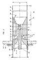
- the burner 51 according to FIG. 2 also consists of a burner tube 61, an atomizing nozzle 62 provided with an ignition electrode 68, an air supply line 63 formed by an extension of the burner tube 61, and an orifice 71 arranged between the latter and the burner tube 61, the opening 72 of which from the atomizing nozzle 62 is penetrated so that it is in turn arranged in the flow direction indicated by the arrow P behind the aperture 71.
- the air supply line 63 is inserted into a wall 53 of a boiler 52, the burner tube 61, which surrounds a combustion chamber 70, thus projects into the boiler room 54 of the boiler 52.
- a mixing element 81 is inserted into the burner tube 61, which together with a casing 66 of the atomizing nozzle 62 and its fuel supply line 65 forms a mixing chamber 82 with an annular cross section.
- an annular channel 83 which is provided between the diaphragm 71 and the mixing element 81 designed as a sleeve 84 and is connected to the boiler chamber 54 via recesses 64 machined into the burner tube 61, the exhaust gas is released by the combustion air flowing out of the diaphragm 71 at high speed sucked in and thus introduced into the mixing chamber with little expenditure of energy and mixed there with the combustion air flowing at high speed.
- the exhaust gas is intimately mixed with the combustion air, the degree of mixing being selectively influenced by the length of the mixing chamber 82, so that optimum combustion at a low temperature level can be achieved in the combustion chamber 70.
- a diffuser 85 attached to the end of the mixing element 81 and / or a conical extension 86 of the mixing chamber 82 provided in the area of the atomizing nozzle 62, the flow rate of the fuel mixture can be reduced in order not to impair the flame formation.
- the cross-sectional area that can be flowed through and designated by C should be dimensioned about 1.4-3 times larger than the free cross-sectional area A of the diaphragm 71, and the annular channel 83 should also be or the recesses 64 have a cross-sectional area B which corresponds approximately to 0.8-2 times the cross-sectional area A of the diaphragm 21.
- its mixing section 1 should extend over an axial length which corresponds to approximately 0.5-10 times the hydraulic diameter of the mixing chamber 82.
- the atomizing nozzle 62 should be arranged at an axial distance L in front of the end of the burner tube 61 which is at least 1.6 times larger is the diameter D of the burner tube 61.
Landscapes
- Engineering & Computer Science (AREA)
- Chemical & Material Sciences (AREA)
- Combustion & Propulsion (AREA)
- Mechanical Engineering (AREA)
- General Engineering & Computer Science (AREA)
Applications Claiming Priority (2)
| Application Number | Priority Date | Filing Date | Title |
|---|---|---|---|
| DE3938786 | 1989-11-23 | ||
| DE3938786A DE3938786A1 (de) | 1989-11-23 | 1989-11-23 | Brenner zur verbrennung von fluessigen oder gasfoermigen brennstoffen |
Publications (1)
| Publication Number | Publication Date |
|---|---|
| EP0433554A1 true EP0433554A1 (fr) | 1991-06-26 |
Family
ID=6394029
Family Applications (2)
| Application Number | Title | Priority Date | Filing Date |
|---|---|---|---|
| EP90116229A Withdrawn EP0433554A1 (fr) | 1989-11-23 | 1990-08-24 | Brûleur pour la combustion de combustibles liquides ou gazeux |
| EP90122073A Expired - Lifetime EP0430011B1 (fr) | 1989-11-23 | 1990-11-19 | Brûleur pour la combustion de combustibles liquides ou gazeux |
Family Applications After (1)
| Application Number | Title | Priority Date | Filing Date |
|---|---|---|---|
| EP90122073A Expired - Lifetime EP0430011B1 (fr) | 1989-11-23 | 1990-11-19 | Brûleur pour la combustion de combustibles liquides ou gazeux |
Country Status (3)
| Country | Link |
|---|---|
| EP (2) | EP0433554A1 (fr) |
| AT (1) | ATE134259T1 (fr) |
| DE (2) | DE3938786A1 (fr) |
Cited By (1)
| Publication number | Priority date | Publication date | Assignee | Title |
|---|---|---|---|---|
| EP0612959A1 (fr) * | 1993-02-23 | 1994-08-31 | D.W. Clysan B.V. | Brûleur à venturi |
Families Citing this family (8)
| Publication number | Priority date | Publication date | Assignee | Title |
|---|---|---|---|---|
| DE4209221A1 (de) * | 1992-03-21 | 1993-09-23 | Deutsche Forsch Luft Raumfahrt | Stickoxidarmer brenner |
| ATE199452T1 (de) * | 1993-12-18 | 2001-03-15 | Deutsch Zentr Luft & Raumfahrt | Einstellbarer blaubrenner |
| DE4430889A1 (de) | 1993-12-18 | 1995-07-06 | Deutsche Forsch Luft Raumfahrt | Verbrennungsoptimierter Blaubrenner |
| DE4415717C2 (de) * | 1994-05-04 | 2001-03-01 | Man B & W Diesel Ag | Brenner |
| DE4415676C2 (de) * | 1994-05-04 | 2001-03-01 | Man B & W Diesel Ag | Brenner |
| DE4436912A1 (de) * | 1994-10-15 | 1996-04-18 | Broetje August Gmbh & Co | Gebläsebrenner mit Brennraum und Verfahren zum Betreiben des Brenners |
| DE19601581A1 (de) * | 1996-01-18 | 1997-07-24 | Broetje August Gmbh & Co | Verfahren zum Betreiben eines Gebläsebrenners zur Durchführung des Verfahrens |
| CN115638408B (zh) * | 2022-10-21 | 2025-08-15 | 济宁华源热电有限公司 | 一种锅炉用微油点火及助燃系统 |
Citations (7)
| Publication number | Priority date | Publication date | Assignee | Title |
|---|---|---|---|---|
| GB833087A (en) * | 1956-10-04 | 1960-04-21 | Petro Chem Process Company Inc | A heavy fuel burner |
| FR1270432A (fr) * | 1960-10-18 | 1961-08-25 | Appareil pour la combustion de combustibles liquides ou gazeux suivant le principe de la recirculation | |
| US3741166A (en) * | 1972-02-10 | 1973-06-26 | F Bailey | Blue flame retention gun burners and heat exchanger systems |
| DE2603988A1 (de) * | 1975-02-06 | 1976-08-19 | Hultgren Karl S H | Vorrichtung an einem oelbrennerkopf |
| JPS55107811A (en) * | 1979-02-14 | 1980-08-19 | Daido Steel Co Ltd | Radiant tube heating device |
| GB2053447A (en) * | 1979-07-09 | 1981-02-04 | Blueray Systems Inc | Blue flame burner |
| DE8910924U1 (de) * | 1989-09-13 | 1989-11-02 | August Brötje GmbH & Co, 2902 Rastede | Brennerkopf eines Gebläsebrenners |
Family Cites Families (1)
| Publication number | Priority date | Publication date | Assignee | Title |
|---|---|---|---|---|
| DE543828C (de) * | 1929-09-11 | 1932-02-10 | Herzoglich Schleswig Holsteini | Pressgasbrenner |
-
1989
- 1989-11-23 DE DE3938786A patent/DE3938786A1/de not_active Withdrawn
-
1990
- 1990-08-24 EP EP90116229A patent/EP0433554A1/fr not_active Withdrawn
- 1990-11-19 DE DE59010136T patent/DE59010136D1/de not_active Expired - Fee Related
- 1990-11-19 EP EP90122073A patent/EP0430011B1/fr not_active Expired - Lifetime
- 1990-11-19 AT AT90122073T patent/ATE134259T1/de not_active IP Right Cessation
Patent Citations (7)
| Publication number | Priority date | Publication date | Assignee | Title |
|---|---|---|---|---|
| GB833087A (en) * | 1956-10-04 | 1960-04-21 | Petro Chem Process Company Inc | A heavy fuel burner |
| FR1270432A (fr) * | 1960-10-18 | 1961-08-25 | Appareil pour la combustion de combustibles liquides ou gazeux suivant le principe de la recirculation | |
| US3741166A (en) * | 1972-02-10 | 1973-06-26 | F Bailey | Blue flame retention gun burners and heat exchanger systems |
| DE2603988A1 (de) * | 1975-02-06 | 1976-08-19 | Hultgren Karl S H | Vorrichtung an einem oelbrennerkopf |
| JPS55107811A (en) * | 1979-02-14 | 1980-08-19 | Daido Steel Co Ltd | Radiant tube heating device |
| GB2053447A (en) * | 1979-07-09 | 1981-02-04 | Blueray Systems Inc | Blue flame burner |
| DE8910924U1 (de) * | 1989-09-13 | 1989-11-02 | August Brötje GmbH & Co, 2902 Rastede | Brennerkopf eines Gebläsebrenners |
Non-Patent Citations (1)
| Title |
|---|
| PATENT ABSTRACTS OF JAPAN vol. 4, no. 158 (M-39)(640) 5 November 1980, & JP-A-55 107811 (DAIDO TOKUSHUKO KK) 19 August 1980, * |
Cited By (1)
| Publication number | Priority date | Publication date | Assignee | Title |
|---|---|---|---|---|
| EP0612959A1 (fr) * | 1993-02-23 | 1994-08-31 | D.W. Clysan B.V. | Brûleur à venturi |
Also Published As
| Publication number | Publication date |
|---|---|
| EP0430011A1 (fr) | 1991-06-05 |
| DE3938786A1 (de) | 1991-05-29 |
| DE59010136D1 (de) | 1996-03-28 |
| ATE134259T1 (de) | 1996-02-15 |
| EP0430011B1 (fr) | 1996-02-14 |
Similar Documents
| Publication | Publication Date | Title |
|---|---|---|
| EP0580683B1 (fr) | Bruleur, en particulier pour turbines a gaz, pour la combustion peu polluante du gaz de houille et d'autres combustibles | |
| EP0902233B1 (fr) | Buse de pulvérisation par pression combinée | |
| EP0274630B1 (fr) | Agencement pour un brûleur | |
| EP1356236B1 (fr) | Brûleur de prémélange et son mode de fonctionnement | |
| DE1551637A1 (de) | Heizvorrichtung | |
| DE2208574A1 (de) | Brennerkopf | |
| EP0433554A1 (fr) | Brûleur pour la combustion de combustibles liquides ou gazeux | |
| DE1751491A1 (de) | Brenner fuer gasfoermige und fluessige Brennstoffe | |
| EP1030106B1 (fr) | Bruleur à flamme bleue optimisant la combustion | |
| EP0683883B1 (fr) | Bruleur a flamme bleue optimisant la combustion | |
| EP0410135B1 (fr) | Brûleur pour la combustion stoechiométrique de combustible liquide ou gazeux | |
| EP0491079B1 (fr) | Tête de brûleur pour la combustion à mélange préalable d'un combustible liquide dans une installation de combustion atmosphérique | |
| EP0809070B1 (fr) | Brûleur avec recirculation des gaz d'échappement | |
| DE2843002C2 (de) | Heizölbrenner | |
| AT395764B (de) | Vormischgasbrenner | |
| AT404399B (de) | Verfahren und brenner zum verbrennen insbesondere flüssiger brennstoffe | |
| EP0114610A1 (fr) | Brûleur à combustion stoechiométrique de combustible liquide ou gazeux | |
| DE3826279A1 (de) | Gasbrenner | |
| DE19824719C2 (de) | Brenner, insbesondere Ölbrenner | |
| EP0683884B1 (fr) | Bruleur a flamme bleue ajustable | |
| DE9000960U1 (de) | Einrichtung zur stufenweisen Verbrennung eines Brennstoff-Primärluft-Gemisches | |
| EP1489352B1 (fr) | Dispositif de mélange pour un brûleur au gaz ou au fioul | |
| DE4330082A1 (de) | Brenner | |
| DE2835335A1 (de) | Brenner fuer durchlauferhitzer | |
| DE4115814C2 (fr) |
Legal Events
| Date | Code | Title | Description |
|---|---|---|---|
| PUAI | Public reference made under article 153(3) epc to a published international application that has entered the european phase |
Free format text: ORIGINAL CODE: 0009012 |
|
| AK | Designated contracting states |
Kind code of ref document: A1 Designated state(s): AT CH DE DK ES FR GB IT LI NL SE |
|
| STAA | Information on the status of an ep patent application or granted ep patent |
Free format text: STATUS: THE APPLICATION IS DEEMED TO BE WITHDRAWN |
|
| 18D | Application deemed to be withdrawn |
Effective date: 19911227 |