EP1356236B1 - Brûleur de prémélange et son mode de fonctionnement - Google Patents
Brûleur de prémélange et son mode de fonctionnement Download PDFInfo
- Publication number
- EP1356236B1 EP1356236B1 EP02710242A EP02710242A EP1356236B1 EP 1356236 B1 EP1356236 B1 EP 1356236B1 EP 02710242 A EP02710242 A EP 02710242A EP 02710242 A EP02710242 A EP 02710242A EP 1356236 B1 EP1356236 B1 EP 1356236B1
- Authority
- EP
- European Patent Office
- Prior art keywords
- fuel
- premix burner
- flow passage
- premix
- inner tube
- Prior art date
- Legal status (The legal status is an assumption and is not a legal conclusion. Google has not performed a legal analysis and makes no representation as to the accuracy of the status listed.)
- Expired - Lifetime
Links
Images


Classifications
-
- F—MECHANICAL ENGINEERING; LIGHTING; HEATING; WEAPONS; BLASTING
- F23—COMBUSTION APPARATUS; COMBUSTION PROCESSES
- F23D—BURNERS
- F23D17/00—Burners for combustion conjointly or alternatively of gaseous or liquid or pulverulent fuel
- F23D17/002—Burners for combustion conjointly or alternatively of gaseous or liquid or pulverulent fuel gaseous or liquid fuel
-
- F—MECHANICAL ENGINEERING; LIGHTING; HEATING; WEAPONS; BLASTING
- F23—COMBUSTION APPARATUS; COMBUSTION PROCESSES
- F23R—GENERATING COMBUSTION PRODUCTS OF HIGH PRESSURE OR HIGH VELOCITY, e.g. GAS-TURBINE COMBUSTION CHAMBERS
- F23R3/00—Continuous combustion chambers using liquid or gaseous fuel
- F23R3/02—Continuous combustion chambers using liquid or gaseous fuel characterised by the air-flow or gas-flow configuration
- F23R3/04—Air inlet arrangements
- F23R3/10—Air inlet arrangements for primary air
- F23R3/12—Air inlet arrangements for primary air inducing a vortex
- F23R3/14—Air inlet arrangements for primary air inducing a vortex by using swirl vanes
-
- F—MECHANICAL ENGINEERING; LIGHTING; HEATING; WEAPONS; BLASTING
- F23—COMBUSTION APPARATUS; COMBUSTION PROCESSES
- F23R—GENERATING COMBUSTION PRODUCTS OF HIGH PRESSURE OR HIGH VELOCITY, e.g. GAS-TURBINE COMBUSTION CHAMBERS
- F23R3/00—Continuous combustion chambers using liquid or gaseous fuel
- F23R3/28—Continuous combustion chambers using liquid or gaseous fuel characterised by the fuel supply
- F23R3/286—Continuous combustion chambers using liquid or gaseous fuel characterised by the fuel supply having fuel-air premixing devices
-
- F—MECHANICAL ENGINEERING; LIGHTING; HEATING; WEAPONS; BLASTING
- F23—COMBUSTION APPARATUS; COMBUSTION PROCESSES
- F23R—GENERATING COMBUSTION PRODUCTS OF HIGH PRESSURE OR HIGH VELOCITY, e.g. GAS-TURBINE COMBUSTION CHAMBERS
- F23R3/00—Continuous combustion chambers using liquid or gaseous fuel
- F23R3/28—Continuous combustion chambers using liquid or gaseous fuel characterised by the fuel supply
- F23R3/34—Feeding into different combustion zones
- F23R3/343—Pilot flames, i.e. fuel nozzles or injectors using only a very small proportion of the total fuel to insure continuous combustion
-
- F—MECHANICAL ENGINEERING; LIGHTING; HEATING; WEAPONS; BLASTING
- F23—COMBUSTION APPARATUS; COMBUSTION PROCESSES
- F23R—GENERATING COMBUSTION PRODUCTS OF HIGH PRESSURE OR HIGH VELOCITY, e.g. GAS-TURBINE COMBUSTION CHAMBERS
- F23R2900/00—Special features of, or arrangements for continuous combustion chambers; Combustion processes therefor
- F23R2900/03343—Pilot burners operating in premixed mode
Definitions
- the invention relates to a premix burner for producing a homogeneously distributed fuel-air mixture for firing a combustion chamber for driving a gas turbine downstream of the combustion chamber.
- premix combustion When burning liquid or gaseous fuel in a combustion chamber of a gas turbine, so-called premix combustion has become established.
- fuel and combustion air are mixed as uniformly as possible and then passed into the combustion chamber and brought to ignition.
- a typical premix burner is for example from EP-387 532 A1 or the US 6161387 A known.
- Such premix burners are so-called double-cone burners, which essentially consist of two hollow, conical partial bodies, which are nested in the direction of flow. The respective central axes of the two body parts are offset from each other. The adjacent walls of the two body parts form in their longitudinal extent tangential slots for the combustion air, which passes in this way into the burner interior.
- a fuel nozzle for liquid fuel is arranged. The fuel is injected at an acute angle into the hollow cone. The resulting conical liquid fuel profile is tangential enclosed inflowing combustion air. In the axial direction, the concentration of the fuel is continuously reduced as a result of mixing with the combustion air.
- the premix burner can also be operated with gaseous fuel.
- gaseous fuel for this purpose, in the region of the tangential slots in the walls of the two partial bodies distributed in the longitudinal direction Gaseinströmö Stammen, the so-called Premixbelochung provided.
- the mixture formation with the combustion air thus begins already in the zone of the inlet slots. It is understood that in this way a mixed operation with both types of fuel is possible.
- the most homogeneous possible fuel concentration is established over the applied annular cross-section. The result is a defined dome-shaped remindströmzone at the burner outlet, at the top, the so-called flame front, the ignition takes place.
- the premix burner described above is uniformly supplied with premix gas along the premix injection, ie in the context of a single-stage premix operation, stability problems arise within the forming return flow zone and the associated flame front, if the fuel mass flow decreases, for example if the gas turbine is operated in the lower load range.
- the penetration depth of the premix gas supply along the premix injection decreases and the core zone of the calotte-shaped flame front within the burner empties out. Due to the instabilities that occur, the flame can be extinguished.
- the premix burner is switched to the so-called pilot mode, in which gaseous fuel is injected near the central fuel nozzle along the premix burner.
- the invention is therefore based on the object to improve a premix burner to the effect that the above-mentioned prior art disadvantages no longer occur or occur only to a considerably reduced extent in appearance.
- the premix burner can be adapted to individual burner conditions in a structurally simple manner and as inexpensively as possible.
- the premix burner constructed according to the invention is basically characterized by two components which can be assembled in a modular manner.
- the premix burner has a premix burner housing that is tube-shaped, i. basically takes the form of a tube or a cup formed open on two sides and is connected downstream via a transition contour with the combustion chamber, which is arranged downstream of a gas turbine.
- the premix burner housing is formed open upstream, so that the housing can be traversed by air.
- a burner lance formed as an inner tube is provided, which protrudes into the interior of the premix burner housing through the upstream opening of the premix burner housing.
- the burner lance is designed such that it encloses a flow channel which is annular in cross section, together with the premix burner housing.
- the burner lance an mecanicuswand, which encloses an inner flow channel.
- the annular flow passage extends along the entire penetration depth of the burner lance within the premix burner housing and joins downstream of the burner lance together with the inner flow channel to a single flow channel portion which is limited only by the transition contour between the premix burner housing and the combustion chamber.
- the transition contour is designed in the manner of a Venturi nozzle, so that a mass flow located within this flow section is subject to a flow velocity increase.
- At least one fuel adding unit for feeding fuel into the inner flow passage is provided in the inner tubule wall of the burner lance.
- the inner tubus wall has at least one further fuel addition unit for feeding fuel into the annular flow passage.
- the fuel addition units can be supplied with liquid or gaseous fuel.
- a swirl generator is preferably mounted on the outside of the inner tube wall of the burner lance, the supply air flowing into the annular flow channel being subjected to a specific swirl number.
- the supply air entering through the swirl generator into the annular flow channel is swirled on the one hand in a flow direction predetermined by the swirl generator and, on the other hand, mixed with liquid and / or gaseous fuel along the annular flow channel.
- the forming within the annular flow channel fuel / air mixture combines when flowing through the transition contour to a uniform cross-sectional flow, which has a homogeneous fuel / air distribution and reaches the ignition in the combustion chamber, in which they burst the swirl flow forms a stable flame front.
- a fuel addition unit is provided in the inner tubing wall through which gaseous fuel is fed into the annular flow passage. Downstream in the flow direction of this fuel addition unit, a second fuel addition unit is provided through which liquid fuel is introduced into the annular flow channel.
- a fuel addition unit is provided in the inner tubing wall through which gaseous fuel is fed into the annular flow passage.
- a second fuel addition unit is provided through which liquid fuel is introduced into the annular flow channel.
- At least one fuel addition unit is provided through which preferably gaseous fuel is fed into the inner flow channel, which is surrounded by the réelletubuswand.
- gas feed it is possible to use the gas feed as a pilot gas or as a piloted Premixgaszubow.
- a fuel addition unit of this type is to be arranged near the downstream end of the burner lance, so that the gas supply takes place axially close to the flame front forming within the combustion chamber.
- a diffusion flame forms, which is particularly useful in lean modes, i. in partial load operation, which is able to stabilize the flame front.
- premix burner designed according to the invention, it is possible, on the one hand, to assemble modular premix burner configurations of different characteristics merely by fitting individually adapted burner lances. On the one hand, this contributes to the cost-effective production of such premix burner systems, on the other hand, one and the same premix burner housing can be equipped with different burner lance modules, should the customer's operating requirements change over time.
- the modular assembly of the premix burner according to the invention is made possible by all components structurally important for the operating behavior of the premix burner are mounted in and on the tube-like burner lance, such as one or more swirl generators as well as suitably positioned fuel adding units.
- a standardized Vormischbrennergepuruse can be used, which can be equipped with differently configured burner lances.
- the burner lance embodied as an inner tube is designed to be substantially rectilinear along its axial extension, so that the inner flow channel has a virtually constant flow cross-section along its extent, then one forms within the above-described premix burner variant Combustion chamber stable flame front off. Such a burner configuration thus leads to a one-stage combustion.
- Decisive for the formation of a two-stage combustion is the formation of the downstream end region of the burner lance as a diffuser through which the swirl flow introduced in the inner flow channel still bursts within the region of the burner lance and forms a stable flame front.
- a corresponding gaseous fuel addition unit is to be positioned within the tube wall between the swirl generator and the diffuser region of the burner lance.
- the modular premix burner assembly of the present invention allows for great variability in the design of a premix burner, ranging from a single stage pilot gas or premixed pilot system to a two stage burner system with two distinctly axially separate flame positions. Such a large variance is only possible by replacing the inner burner lance.
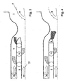
- FIG. 1 is almost everything FIGS. 1 to 9 a tubular or tubular premix burner housing 1 is shown, which is open at its left end shown in the drawing.
- the premix burner housing 1 is basically traversed in the drawing plane from left to right with supply air 12, 13.
- a transition contour 2 is provided, which tapers the flow cross-section of the premix burner housing in the manner of a venturi nozzle.
- the combustion chamber 3 follows seamlessly, in which, as will be explained in detail below, a stable flame front 4 is formed.
- the structure described above can be found in all embodiments according to the FIGS. 1 to 9 again, so that this basic structure will not be discussed further.
- a burner lance 5 designed as an inner tube is introduced, which has an inner tube wall 51, with which it encloses an annular flow channel 6 together with the premix burner housing 1.
- an inner flow channel 7 is enclosed by the inner inner tube wall 51.
- the burner lance 5 has according to the embodiments of the FIGS. 1 to 7 an almost rectilinear mecanicuswandverlauf, so that the flow cross-sections of both the annular and inner flow channel along the extension of the burner lance 5 remain almost constant.
- fuel addition units 8, 9, 10 Inside the inner tube wall 51 are fuel addition units 8, 9, 10. From the fuel adding unit 8, gaseous fuel flows into the annular one Flow channel 6, whereas from the fuel addition unit 9 axially downstream of the fuel addition unit 8 liquid fuel is fed into the annular flow channel 6. Gaseous fuel is fed into the inner flow passage 7 through the fuel addition unit 10 located near the downstream end of the burner lance 5. Likewise located on the burner lance 5 a swirl generator 11, which ensures a targeted turbulence of the inflowing into the annular flow channel 6 secondary air 12.
- the twisted secondary air 12 mixes along the annular flow channel 6 with the fuel types fed to a nearly homogeneously distributed fuel / air mixture brought to merge after merging in the transition contour 2 and corresponding increase in speed due to the Venturi nozzle contour in the combustion chamber 3 becomes. Due to the bursting of the swirl flow, a dynamic backflow zone 41 is established, which is characterized by the spatially stable flame front 4. For purposes of stabilization of forming within the combustion chamber 3 flame front 4, especially in low load ranges, ie lean modes, a targeted pilot gas supply via the fuel addition unit 10, which leads due to their proximity to the flame front 4 to a diffusion flame and thus the flame front 4 to stabilize can.
- the inner flow channel 7 is also open upstream, but without swirl generator, so that primary air 13 can be supplied through the inner flow channel 7.
- the premix burner housing 1 connected to the combustion chamber 3 can be equipped with individually designed burner lances. This will be described from the non-conclusive number below figures. To avoid repetition, system components already described and provided with reference numerals are not explained again in detail. For the rest, reference is made to the attached list of reference numerals.
- Fig. 2 In contrast to Fig. 1 has the in Fig. 2 shown premix burner variant on a fuel addition unit 8 ', which is not integrated within the burner lance 5, but from the outside through the premix burner housing 1 gaseous fuel into the annular flow channel 6 feeds.
- the remaining structure is similar to that of the embodiment according to Fig. 1 ,
- This in Fig. 2 illustrated embodiment is intended to show that a correspondingly configured burner lance 5 can be introduced into a premix burner housing 1, which in turn has certain peripheral components, such as a fuel addition unit 8 'for supplying gaseous fuel. This illustrates the almost arbitrarily available variability for the configuration of the burner lance 5.
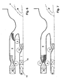
- Fig. 3 shows a premix burner with a different from the embodiment according to Fig. 1 axially spaced from the downstream end of the burner lance 5 fuel addition unit 10 for feeding gaseous fuel into the inner flow channel 7.
- a pilot gas supply into the inner flow channel 7, which is axially far from the forming inside the combustion chamber 3 flame front 4 and does not come as a diffusion flame for ignition is able to mix with the supplied primary air 13 and mix with the remaining fuel / air mixture resulting from the annular flow channel 6.
- a premix pilot gas feed serves to increase the performance of the premix burner for gas turbine operation under high load.
- Fig. 4 a liquid fuel injection directly at the end of the burner lance 5 before.
- the axial spatial position of the flame front 4 can be influenced and, moreover, the fuel / air ratio in the mixing area can be influenced.
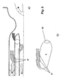
- Fig. 5 a shows a multi-stage fuel addition unit 8 "for feeding gaseous fuel into the annular flow channel 6.
- the burner lance 5 is shown in perspective, which has an outlet opening 52, through which the inner flow channel 7 opens.
- a plurality of fuel supply openings 8 are provided axially one behind the other, through which gaseous fuel flows into the annular flow channel 6.
- the fuel addition openings 8" can either be arranged linearly axially one behind the other or also be positioned in a circular offset relationship to one another.
- annular and inner flow passages have a conically narrowed flow area, with the fuel addition unit at the narrowest flow area, to avoid local flashback.
- a further swirl generator 14 is provided in the inner flow channel 7, which swirls the primary air 13 with a certain swirl number.
- a fuel addition unit 10 integrated downstream of the swirl generator 14 within the burner lance 5 through which gaseous fuel is fed into the inner flow passage 7, a fuel / air swirl flow is created of the widening flow cross-section in the region of a first sudströmzone 161 bursts, reaches the ignition and forms a first stable flame front 16.
- the flue gases which are formed within the first combustion stage are fed to the combustion process downstream axially downstream, starting with the stable flame front 4, whereby the NO x exhaust gas values can be considerably reduced.
- Fig. 9 shows a difference to Fig. 8 rectilinear diffuser 15 through which a two-stage combustion can be realized in the same way.
Landscapes
- Engineering & Computer Science (AREA)
- Chemical & Material Sciences (AREA)
- Combustion & Propulsion (AREA)
- Mechanical Engineering (AREA)
- General Engineering & Computer Science (AREA)
- Gas Burners (AREA)
Claims (20)
- Brûleur à prémélange, dans lequel du combustible et de l'air peuvent être mélangés pour donner un mélange de combustible et d'air, pour former au moins un front de flamme stable (4) à l'intérieur d'une chambre de combustion (3) disposée en aval pour l'entraînement d'une turbine à gaz montée derrière la chambre de combustion (3), comprenant :- un carter de brûleur à prémélange (1), qui est réalisé en amont sous forme ouverte en forme de tube, qui est connecté en aval par le biais d'un contour de transition (2) à la chambre de combustion (3) et qui peut être parcouru par de l'air,- une lance de brûleur (5) réalisée sous forme de tube interne, qui pénètre du côté amont dans l'intérieur du carter du brûleur à prémélange (1), qui forme un canal d'écoulement (6) de forme annulaire en section transversale avec le carter du brûleur à prémélange (1), et qui présente une paroi de tube interne, qui entoure un canal d'écoulement interne (7), et dans laquelle au moins une unité d'apport de combustible (10) est prévue pour injecter du combustible dans le canal d'écoulement interne (7), et au moins une autre unité d'apport de combustible (8, 9) est prévue pour injecter du combustible dans le canal d'écoulement annulaire (6) de telle sorte que le mélange de combustible et d'air s'allume à l'intérieur du front de flamme (4) en aval du tube interne dans la région de la chambre de combustion (3).
- Brûleur à prémélange selon la revendication 1,
caractérisé en ce que le tube interne (5) est réalisé en amont et en aval sous forme ouverte et peut être parcouru par de l'air (12, 13). - Brûleur à prémélange selon la revendication 1 ou 2,
caractérisé en ce que le tube interne (5) se termine en aval dans la région du contour de transition (2). - Brûleur à prémélange selon l'une quelconque des revendications 1 à 3,
caractérisé en ce que le contour de transition (2) réduit le diamètre intérieur du carter du brûleur à prémélange (1) en aval et présente une section transversale d'écoulement s'élargissant vers la chambre de combustion (3), à la manière d'une buse de Venturi. - Brûleur à prémélange selon l'une quelconque des revendications 1 à 4,
caractérisé en ce que la lance de brûleur (5) réalisée sous forme de tube interne peut être insérée sous forme modulaire dans le carter du brûleur à prémélange (1). - Brûleur à prémélange selon l'une quelconque des revendications 1 à 5, caractérisé en ce que l'on monte sur le côté extérieur de la paroi du tube interne un générateur de tourbillon (11) pour l'air traversant le canal d'écoulement annulaire (6).
- Brûleur à prémélange selon l'une quelconque des revendications 1 à 6,
caractérisé en ce que l'on prévoit sur le côté intérieur de la paroi du tube interne un générateur de tourbillon (14) pour l'air (13) traversant le canal d'écoulement interne. - Brûleur à prémélange selon l'une quelconque des revendications 1 à 7,
caractérisé en ce que du combustible gazeux ou liquide peut être injecté à travers les unités d'apport de combustible (8, 9, 10) à la fois pour l'injection de combustible dans le canal d'écoulement interne (7) et dans le canal d'écoulement annulaire (6). - Brûleur à prémélange selon l'une quelconque des revendications 1 à 8,
caractérisé en ce que l'on prévoit le long du tube interne au moins une unité d'apport de combustible (8), à travers laquelle du combustible gazeux peut être injecté dans le canal d'écoulement annulaire (6),
en ce qu'en aval de l'au moins une unité d'apport de combustible (8), on prévoit au moins une autre unité d'apport de combustible (9), au moyen de laquelle du combustible liquide peut être injecté dans le canal d'écoulement annulaire (6). - Brûleur à prémélange selon l'une quelconque des revendications 1 à 9,
caractérisé en ce que l'on prévoit au moins une unité d'apport de combustible (9) en aval au niveau du tube interne, à travers laquelle du combustible liquide peut être injecté dans une région de mélange entourée par le contour de transition (2), en amont du front de flamme (4). - Brûleur à prémélange selon l'une quelconque des revendications 1 à 10,
caractérisé en ce qu'au moins deux unités d'apport de combustible (8, 9) sont disposées axialement l'une derrière l'autre au niveau du tube interne pour l'injection de combustible dans le canal d'écoulement annulaire (6) ou le canal d'écoulement interne (7). - Brûleur à prémélange selon l'une quelconque des revendications 1 à 11,
caractérisé en ce que la paroi du tube interne est réalisée de telle sorte que le canal d'écoulement interne (7) présente une section transversale d'écoulement sensiblement uniforme le long de l'étendue axiale de la lance de brûleur (5). - Brûleur à prémélange selon la revendication 12,
caractérisé en ce qu'une unité d'apport de combustible (10) pour l'injection de combustible gazeux dans le canal d'écoulement interne (7) est prévue dans la région de l'extrémité aval de la lance de brûleur (5) et sert d'alimentation en gaz pilote. - Brûleur à prémélange selon la revendication 12,
caractérisé en ce qu'une unité d'apport de combustible (10) pour l'injection de combustible gazeux dans le canal d'écoulement interne (7) est prévue en amont de l'extrémité aval de la lance de brûleur (5) et sert d'alimentation en gaz pilote de prémélange. - Brûleur à prémélange selon l'une quelconque des revendications 1 à 11,
caractérisé en ce que la paroi du tube interne est réalisée de telle sorte que le canal d'écoulement interne (7) présente une section transversale d'écoulement sensiblement uniforme le long de l'étendue axiale de la lance de brûleur (5) et s'élargit à l'intérieur de la région aval de la lance de brûleur (5), et
en ce qu'en amont à l'intérieur du canal d'écoulement interne, on prévoit un générateur de tourbillon (14). - Brûleur à prémélange selon la revendication 15,
caractérisé en ce qu'au moins une unité d'apport de combustible (10) pour injecter du combustible gazeux dans le canal d'écoulement interne (7) est prévue directement en amont du canal d'écoulement interne s'élargissant à l'intérieur de la paroi du tube interne, et en ce qu'il se forme deux fronts de flamme (16, 4) stables et séparés axialement, un premier (16) à l'intérieur du canal d'écoulement interne s'élargissant en section transversale d'écoulement et un deuxième (4) en aval du tube interne dans la région de la chambre de combustion (3). - Brûleur à prémélange selon l'une quelconque des revendications 1 à 14,
caractérisé en ce que le carter du brûleur à prémélange (1) et/ou la paroi du tube interne de la lance de brûleur (5) présente, à l'emplacement d'une unité d'apport de combustible, un contour réduisant le canal d'écoulement annulaire (6) ou interne (7) à la manière d'une buse de Venturi. - Procédé pour chauffer une chambre de combustion (3) pour l'entraînement d'une turbine à gaz en utilisant un brûleur à prémélange modulaire selon l'une quelconque des revendications 1 à 17,
caractérisé en ce qu'à l'intérieur du canal d'écoulement annulaire (6) est produit un écoulement tourbillonnaire constitué d'un mélange de combustible et d'air, qui constitue un front de flamme stable (4) à l'intérieur de la chambre de combustion (3) après le passage à travers le contour de transition (2), et
en ce que du combustible gazeux est introduit dans le canal d'écoulement interne (7) de telle sorte que l'apport de combustible s'effectue à proximité de l'extrémité aval de la lance de brûleur (5) et serve d'alimentation en gaz pilote, et qu'il forme une flamme de diffusion ou qu'il s'effectue à distance en amont de l'extrémité aval de la lance de brûleur (5) et serve d'apport en gaz de prémélange. - Procédé pour chauffer une chambre de combustion (3) pour l'entraînement d'une turbine à gaz en utilisant un brûleur à prémélange modulaire selon l'une quelconque des revendications 15 à 17,
caractérisé en ce qu'à l'intérieur du canal d'écoulement annulaire (6) est produit un écoulement tourbillonnaire constitué d'un mélange de combustible et d'air, qui constitue un front de flamme stable (4) à l'intérieur de la chambre de combustion (3) après le passage à travers le contour de transition (2), et en ce que du combustible gazeux est introduit dans le canal d'écoulement interne (7) qui s'élargit dans la région aval de la lance de brûleur (5), de telle sorte qu'un front de flamme supplémentaire (16) se forme axialement en amont du front de flamme (4) se formant à l'intérieur de la chambre de combustion (3). - Utilisation du brûleur à prémélange selon l'une quelconque des revendications 1 à 17 en tant que brûleur à prémélange modulaire en prévoyant un carter de brûleur à prémélange (1) en tant que module standard et en fournissant différentes lances de brûleur (5) réalisées à chaque fois sous forme de tube interne, qui sont configurées différemment avec des unités d'apport de combustible (8, 9, 10) et/ou des générateurs de tourbillon (11, 14), et qui peuvent être intégrées sous forme modulaire à l'intérieur du carter du brûleur à prémélange (1).
Applications Claiming Priority (3)
| Application Number | Priority Date | Filing Date | Title |
|---|---|---|---|
| DE10104695 | 2001-02-02 | ||
| DE10104695.2A DE10104695B4 (de) | 2001-02-02 | 2001-02-02 | Vormischbrenner für eine Gasturbine |
| PCT/IB2002/000384 WO2002061339A1 (fr) | 2001-02-02 | 2002-02-01 | Brûleur de prémélange et son mode de fonctionnement |
Publications (2)
| Publication Number | Publication Date |
|---|---|
| EP1356236A1 EP1356236A1 (fr) | 2003-10-29 |
| EP1356236B1 true EP1356236B1 (fr) | 2008-11-26 |
Family
ID=7672609
Family Applications (1)
| Application Number | Title | Priority Date | Filing Date |
|---|---|---|---|
| EP02710242A Expired - Lifetime EP1356236B1 (fr) | 2001-02-02 | 2002-02-01 | Brûleur de prémélange et son mode de fonctionnement |
Country Status (4)
| Country | Link |
|---|---|
| US (1) | US6895759B2 (fr) |
| EP (1) | EP1356236B1 (fr) |
| DE (2) | DE10104695B4 (fr) |
| WO (1) | WO2002061339A1 (fr) |
Families Citing this family (20)
| Publication number | Priority date | Publication date | Assignee | Title |
|---|---|---|---|---|
| DE10104695B4 (de) | 2001-02-02 | 2014-11-20 | Alstom Technology Ltd. | Vormischbrenner für eine Gasturbine |
| DE10160997A1 (de) | 2001-12-12 | 2003-07-03 | Rolls Royce Deutschland | Magervormischbrenner für eine Gasturbine sowie Verfahren zum Betrieb eines Magervormischbrenners |
| EP1624252A1 (fr) * | 2004-08-06 | 2006-02-08 | Siemens Aktiengesellschaft | Brûleur, turbine à gaz et procédé opératoire pour un brûleur |
| WO2006069861A1 (fr) * | 2004-12-23 | 2006-07-06 | Alstom Technology Ltd | Bruleur de premelange dote d'un parcours de melange |
| ITTO20050208A1 (it) * | 2005-03-30 | 2006-09-30 | Ansaldo Energia Spa | Gruppo bruciatore a gas per una turbina a gas |
| JP2007147125A (ja) * | 2005-11-25 | 2007-06-14 | Mitsubishi Heavy Ind Ltd | ガスタービン燃焼器 |
| CA2630721C (fr) * | 2005-12-14 | 2012-06-19 | Rolls-Royce Power Engineering Plc | Injecteurs de premelange de turbine a gaz |
| US7721553B2 (en) * | 2006-07-18 | 2010-05-25 | Siemens Energy, Inc. | Method and apparatus for detecting a flashback condition in a gas turbine |
| RU2348864C2 (ru) * | 2007-03-19 | 2009-03-10 | Общество с ограниченной ответственностью "Научно-производственное предприятие "ЭСТ" | Горелка |
| WO2009019113A2 (fr) † | 2007-08-07 | 2009-02-12 | Alstom Technology Ltd | Brûleur pour une chambre de combustion d'un turbogroupe |
| JP5412283B2 (ja) * | 2007-08-10 | 2014-02-12 | 川崎重工業株式会社 | 燃焼装置 |
| EP2058590B1 (fr) * | 2007-11-09 | 2016-03-23 | Alstom Technology Ltd | Procédé de fonctionnement d'un brûleur |
| EP2225488B1 (fr) | 2007-11-27 | 2013-07-17 | Alstom Technology Ltd | Brûleur à prémélange pour une turbine à gaz |
| MY157598A (en) * | 2009-09-13 | 2016-06-30 | Lean Flame Inc | Method of fuel staging in combustion apparatus |
| US8677760B2 (en) * | 2010-01-06 | 2014-03-25 | General Electric Company | Fuel nozzle with integrated passages and method of operation |
| US9194586B2 (en) * | 2011-12-07 | 2015-11-24 | Pratt & Whitney Canada Corp. | Two-stage combustor for gas turbine engine |
| WO2014201135A1 (fr) | 2013-06-11 | 2014-12-18 | United Technologies Corporation | Chambre de combustion à étagement axial pour un moteur à turbine à gaz |
| US10393030B2 (en) | 2016-10-03 | 2019-08-27 | United Technologies Corporation | Pilot injector fuel shifting in an axial staged combustor for a gas turbine engine |
| EP3486570B1 (fr) * | 2017-11-15 | 2023-06-21 | Ansaldo Energia Switzerland AG | Chambre de combustion de second étage pour chambre de combustion séquentielle d'une turbine à gaz |
| CN115745711B (zh) * | 2022-11-02 | 2023-11-24 | 北京卫星环境工程研究所 | 一种氢氧爆轰驱动轻气炮的铝粉预混合反应室 |
Family Cites Families (16)
| Publication number | Priority date | Publication date | Assignee | Title |
|---|---|---|---|---|
| SE371685B (fr) * | 1972-04-21 | 1974-11-25 | Stal Laval Turbin Ab | |
| CH678757A5 (fr) * | 1989-03-15 | 1991-10-31 | Asea Brown Boveri | |
| US5749217A (en) * | 1991-12-26 | 1998-05-12 | Caterpillar Inc. | Low emission combustion system for a gas turbine engine |
| US5295352A (en) * | 1992-08-04 | 1994-03-22 | General Electric Company | Dual fuel injector with premixing capability for low emissions combustion |
| US5452574A (en) * | 1994-01-14 | 1995-09-26 | Solar Turbines Incorporated | Gas turbine engine catalytic and primary combustor arrangement having selective air flow control |
| DE19507088B4 (de) * | 1995-03-01 | 2005-01-27 | Alstom | Vormischbrenner |
| EP0851990B1 (fr) * | 1995-09-22 | 2001-12-05 | Siemens Aktiengesellschaft | Bruleur, en particulier pour turbine a gaz |
| DE19542164A1 (de) * | 1995-11-11 | 1997-05-15 | Abb Research Ltd | Vormischbrenner |
| DE19545310B4 (de) * | 1995-12-05 | 2008-06-26 | Alstom | Vormischbrenner |
| US5899076A (en) * | 1996-12-20 | 1999-05-04 | United Technologies Corporation | Flame disgorging two stream tangential entry nozzle |
| EP0995066B1 (fr) * | 1997-07-17 | 2001-09-26 | Siemens Aktiengesellschaft | Agencement de bruleurs pour une installation de chauffe, notamment une chambre de combustion de turbine a gaz |
| US6141967A (en) * | 1998-01-09 | 2000-11-07 | General Electric Company | Air fuel mixer for gas turbine combustor |
| DE19839085C2 (de) * | 1998-08-27 | 2000-06-08 | Siemens Ag | Brenneranordnung mit primärem und sekundärem Pilotbrenner |
| US6161387A (en) * | 1998-10-30 | 2000-12-19 | United Technologies Corporation | Multishear fuel injector |
| DE10104695B4 (de) | 2001-02-02 | 2014-11-20 | Alstom Technology Ltd. | Vormischbrenner für eine Gasturbine |
| US6539721B2 (en) * | 2001-07-10 | 2003-04-01 | Pratt & Whitney Canada Corp. | Gas-liquid premixer |
-
2001
- 2001-02-02 DE DE10104695.2A patent/DE10104695B4/de not_active Expired - Fee Related
-
2002
- 2002-02-01 EP EP02710242A patent/EP1356236B1/fr not_active Expired - Lifetime
- 2002-02-01 DE DE50213051T patent/DE50213051D1/de not_active Expired - Fee Related
- 2002-02-01 WO PCT/IB2002/000384 patent/WO2002061339A1/fr not_active Application Discontinuation
-
2003
- 2003-07-30 US US10/629,605 patent/US6895759B2/en not_active Expired - Lifetime
Also Published As
| Publication number | Publication date |
|---|---|
| EP1356236A1 (fr) | 2003-10-29 |
| US20040055307A1 (en) | 2004-03-25 |
| DE10104695A1 (de) | 2002-08-08 |
| DE50213051D1 (de) | 2009-01-08 |
| WO2002061339A1 (fr) | 2002-08-08 |
| DE10104695B4 (de) | 2014-11-20 |
| US6895759B2 (en) | 2005-05-24 |
Similar Documents
| Publication | Publication Date | Title |
|---|---|---|
| EP1356236B1 (fr) | Brûleur de prémélange et son mode de fonctionnement | |
| EP2115353B1 (fr) | Chambre de combustion pour une turbine à gaz | |
| EP1828684A1 (fr) | Bruleur de premelange dote d'un parcours de melange | |
| DE3222347C2 (fr) | ||
| EP1802915B1 (fr) | Bruleur pour turbine a gaz | |
| EP2116766B1 (fr) | Brûleur avec lance à combustible | |
| EP0918191B1 (fr) | Brûleur pour la mise en oeuvre d'un générateur de chaleur | |
| EP1754002B1 (fr) | Brûleur étagé à prémélange comprenant in injecteur de carburant liquide | |
| EP0801268B1 (fr) | Méthode d'exploitation d'une chambre de combustion pour turbine à gaz | |
| EP0833105A2 (fr) | Brûleur à prémélange | |
| EP1213536B1 (fr) | Brûleur à prémélange avec brûleur pilote catalytique | |
| EP1864056A1 (fr) | Bruleur de premelange destine a une chambre de combustion de turbine a gaz | |
| EP1807656A1 (fr) | Bruleur a premelange | |
| EP0995066B1 (fr) | Agencement de bruleurs pour une installation de chauffe, notamment une chambre de combustion de turbine a gaz | |
| DE19545310A1 (de) | Vormischbrenner | |
| EP0777081A2 (fr) | Brûleur à prémélange | |
| EP1235033B1 (fr) | Chambre de combustion annulaire et méthode d'opération de la dite chambre | |
| DE102004049491A1 (de) | Vormischbrenner | |
| EP0481111A1 (fr) | Chambre de combustion pour turbine à gaz | |
| DE10051221A1 (de) | Brenner mit gestufter Brennstoff-Eindüsung | |
| CH679692A5 (fr) | ||
| EP1510755B1 (fr) | Brûleur avec lance et alimentation étagée en carburant | |
| DE4445279A1 (de) | Einspritzdüse | |
| DE4412315A1 (de) | Verfahren und Vorrichtung zum Betreiben der Brennkammer einer Gasturbine | |
| EP0727611A1 (fr) | Chambre de combustion avec combustion en deux étages |
Legal Events
| Date | Code | Title | Description |
|---|---|---|---|
| PUAI | Public reference made under article 153(3) epc to a published international application that has entered the european phase |
Free format text: ORIGINAL CODE: 0009012 |
|
| 17P | Request for examination filed |
Effective date: 20030718 |
|
| AK | Designated contracting states |
Kind code of ref document: A1 Designated state(s): AT BE CH CY DE DK ES FI FR GB GR IE IT LI LU MC NL PT SE TR |
|
| AX | Request for extension of the european patent |
Extension state: AL LT LV MK RO SI |
|
| RAP1 | Party data changed (applicant data changed or rights of an application transferred) |
Owner name: ALSTOM TECHNOLOGY LTD |
|
| GRAP | Despatch of communication of intention to grant a patent |
Free format text: ORIGINAL CODE: EPIDOSNIGR1 |
|
| GRAS | Grant fee paid |
Free format text: ORIGINAL CODE: EPIDOSNIGR3 |
|
| GRAA | (expected) grant |
Free format text: ORIGINAL CODE: 0009210 |
|
| AK | Designated contracting states |
Kind code of ref document: B1 Designated state(s): DE GB |
|
| REG | Reference to a national code |
Ref country code: GB Ref legal event code: FG4D Free format text: NOT ENGLISH |
|
| REF | Corresponds to: |
Ref document number: 50213051 Country of ref document: DE Date of ref document: 20090108 Kind code of ref document: P |
|
| PGFP | Annual fee paid to national office [announced via postgrant information from national office to epo] |
Ref country code: DE Payment date: 20090219 Year of fee payment: 8 |
|
| PLBE | No opposition filed within time limit |
Free format text: ORIGINAL CODE: 0009261 |
|
| STAA | Information on the status of an ep patent application or granted ep patent |
Free format text: STATUS: NO OPPOSITION FILED WITHIN TIME LIMIT |
|
| 26N | No opposition filed |
Effective date: 20090827 |
|
| PG25 | Lapsed in a contracting state [announced via postgrant information from national office to epo] |
Ref country code: DE Free format text: LAPSE BECAUSE OF NON-PAYMENT OF DUE FEES Effective date: 20100901 |
|
| PGFP | Annual fee paid to national office [announced via postgrant information from national office to epo] |
Ref country code: GB Payment date: 20170216 Year of fee payment: 16 |
|
| REG | Reference to a national code |
Ref country code: GB Ref legal event code: 732E Free format text: REGISTERED BETWEEN 20170727 AND 20170802 |
|
| GBPC | Gb: european patent ceased through non-payment of renewal fee |
Effective date: 20180201 |
|
| PG25 | Lapsed in a contracting state [announced via postgrant information from national office to epo] |
Ref country code: GB Free format text: LAPSE BECAUSE OF NON-PAYMENT OF DUE FEES Effective date: 20180201 |