EP0432730A2 - Vorrichtung zur Messung des Kalziumgehaltes von Knochen - Google Patents
Vorrichtung zur Messung des Kalziumgehaltes von Knochen Download PDFInfo
- Publication number
- EP0432730A2 EP0432730A2 EP90123814A EP90123814A EP0432730A2 EP 0432730 A2 EP0432730 A2 EP 0432730A2 EP 90123814 A EP90123814 A EP 90123814A EP 90123814 A EP90123814 A EP 90123814A EP 0432730 A2 EP0432730 A2 EP 0432730A2
- Authority
- EP
- European Patent Office
- Prior art keywords
- ray
- bone mineral
- mineral content
- filters
- measuring apparatus
- Prior art date
- Legal status (The legal status is an assumption and is not a legal conclusion. Google has not performed a legal analysis and makes no representation as to the accuracy of the status listed.)
- Granted
Links
Images


Classifications
-
- G—PHYSICS
- G01—MEASURING; TESTING
- G01N—INVESTIGATING OR ANALYSING MATERIALS BY DETERMINING THEIR CHEMICAL OR PHYSICAL PROPERTIES
- G01N23/00—Investigating or analysing materials by the use of wave or particle radiation, e.g. X-rays or neutrons, not covered by groups G01N3/00 – G01N17/00, G01N21/00 or G01N22/00
- G01N23/02—Investigating or analysing materials by the use of wave or particle radiation, e.g. X-rays or neutrons, not covered by groups G01N3/00 – G01N17/00, G01N21/00 or G01N22/00 by transmitting the radiation through the material
- G01N23/06—Investigating or analysing materials by the use of wave or particle radiation, e.g. X-rays or neutrons, not covered by groups G01N3/00 – G01N17/00, G01N21/00 or G01N22/00 by transmitting the radiation through the material and measuring the absorption
- G01N23/083—Investigating or analysing materials by the use of wave or particle radiation, e.g. X-rays or neutrons, not covered by groups G01N3/00 – G01N17/00, G01N21/00 or G01N22/00 by transmitting the radiation through the material and measuring the absorption the radiation being X-rays
-
- A—HUMAN NECESSITIES
- A61—MEDICAL OR VETERINARY SCIENCE; HYGIENE
- A61B—DIAGNOSIS; SURGERY; IDENTIFICATION
- A61B6/00—Apparatus for radiation diagnosis, e.g. combined with radiation therapy equipment
- A61B6/40—Apparatus for radiation diagnosis, e.g. combined with radiation therapy equipment with arrangements for generating radiation specially adapted for radiation diagnosis
- A61B6/4035—Apparatus for radiation diagnosis, e.g. combined with radiation therapy equipment with arrangements for generating radiation specially adapted for radiation diagnosis the source being combined with a filter or grating
-
- A—HUMAN NECESSITIES
- A61—MEDICAL OR VETERINARY SCIENCE; HYGIENE
- A61B—DIAGNOSIS; SURGERY; IDENTIFICATION
- A61B6/00—Apparatus for radiation diagnosis, e.g. combined with radiation therapy equipment
- A61B6/48—Diagnostic techniques
- A61B6/482—Diagnostic techniques involving multiple energy imaging
-
- A—HUMAN NECESSITIES
- A61—MEDICAL OR VETERINARY SCIENCE; HYGIENE
- A61B—DIAGNOSIS; SURGERY; IDENTIFICATION
- A61B6/00—Apparatus for radiation diagnosis, e.g. combined with radiation therapy equipment
- A61B6/50—Clinical applications
- A61B6/505—Clinical applications involving diagnosis of bone
-
- G—PHYSICS
- G21—NUCLEAR PHYSICS; NUCLEAR ENGINEERING
- G21K—TECHNIQUES FOR HANDLING PARTICLES OR IONISING RADIATION NOT OTHERWISE PROVIDED FOR; IRRADIATION DEVICES; GAMMA RAY OR X-RAY MICROSCOPES
- G21K1/00—Arrangements for handling particles or ionising radiation, e.g. focusing or moderating
- G21K1/02—Arrangements for handling particles or ionising radiation, e.g. focusing or moderating using diaphragms, collimators
- G21K1/04—Arrangements for handling particles or ionising radiation, e.g. focusing or moderating using diaphragms, collimators using variable diaphragms, shutters, choppers
- G21K1/043—Arrangements for handling particles or ionising radiation, e.g. focusing or moderating using diaphragms, collimators using variable diaphragms, shutters, choppers changing time structure of beams by mechanical means, e.g. choppers, spinning filter wheels
-
- G—PHYSICS
- G21—NUCLEAR PHYSICS; NUCLEAR ENGINEERING
- G21K—TECHNIQUES FOR HANDLING PARTICLES OR IONISING RADIATION NOT OTHERWISE PROVIDED FOR; IRRADIATION DEVICES; GAMMA RAY OR X-RAY MICROSCOPES
- G21K1/00—Arrangements for handling particles or ionising radiation, e.g. focusing or moderating
- G21K1/10—Scattering devices; Absorbing devices; Ionising radiation filters
Definitions
- the present invention relates to a bone mineral content measuring apparatus for measuring the bone mineral content of an object to be examined by X rays.
- the bone mineral content in a living body is useful information for the diagnosis of a disease relating to a bone.
- the bone mineral content is used for the diagnosis of, for example, osteogenesis aberration, bone deficiency and a disease in a bone.
- a general bone mineral content measuring apparatus measures a bone mineral content by using radiation. That is, by irradiating the radiation onto a living body which is an object to be examined from the outside of the living body and detecting the radiation which has passed through the living body, the bone mineral content in the living body is measured from the amount of radiation absorbed into calcium, etc., which are the main components of a bone.
- a conventional bone mineral content measuring apparatus is provided with a radiation source which produces, for example, ⁇ -rays and the bone mineral content is measured by the ⁇ -rays generated by the radiation source.
- the conventional bone mineral content measuring apparatus is disadvantageous in that the maintenance and handling of the radiation source is troublesome and in that the amount of radiation is lowered with the passage of time.
- This bone mineral content measuring apparatus includes an X-ray generating device for generating X-rays having a continuous spectrum (white spectrum), a monochromator for converting the X-rays generated by the X-ray generating device into X-rays having a monochromatic spectrum, and an X-ray detecting device for detecting the X-rays which have passed through the living body, and obtains the bone mineral content of the living body from the detected X-ray detection data.
- a diffraction grating is used as the monochromator.
- this bone mineral content measuring apparatus using X-rays it is possible to eliminate the problems caused by an X-ray radiation source and to stably measure a bone mineral content for a long term.
- a bone mineral content is measured by using X-rays having a plurality of different energy values. It is therefore possible to discriminate the soft tissue from the bones in the living body in the X-ray detection data, thereby realizing the measurement of a bone mineral content without the need for a water bag which is conventionally necessary for wrapping the region to be measured.
- the conventional bone mineral content measuring apparatus using X-rays in which it is necessary to convert X-rays having a continuous spectrum into X-rays having a monochromatic spectrum before the living body is irradiated with the X-rays, is disadvantageous in that since the conversion for a monochromatic spectrum is difficult, the monochromator has a complicated structure.
- a bone mineral content measuring apparatus which is capable of measuring a bone mineral content without the need for complicated treatment of the X-rays having a continuous spectrum which are generated by an X-ray generating device is demanded.
- a bone mineral content measuring apparatus which is capable of measuring a bone mineral content at the optimum X-ray intensity by adjusting the intensity of the X-rays in correspondence to the region of the living body being measured is demanded.
- a bone mineral content measuring apparatus mainly comprises an X-ray generating device, an X-ray detecting device, a filtering device including at least a pair of X-ray filters and a filter switching device for switching X-ray filters, a data analyzer and a display unit.
- X-rays having a continuous spectrum are first generated by the X-ray generating device.
- the X-rays which have passed through the object to be examined are detected by the X-ray detecting device.
- the X-rays generated are subjected to spectrum conversion when they pass through the X-ray filter which is selected by the filter switching device before the X-rays are irradiated onto the object to be examined or after they have passed through the object.
- the pair of X-ray filters are respectively composed of substances having different X-ray absorbing characteristics. In other words, there are K-absorption edges at different energy values which are approximate to each other.
- the X-ray detection data detected by the X-ray detecting device are inputted to a data analyzer.
- a bone mineral content analyzing circuit provided in the data analyzer obtains the bone mineral content (BMC) of the object to be examined on the basis of the difference between the data detected by the X-rays through one X-ray filter and the data detected by the X-rays through the other X-ray filter.
- BMC bone mineral content
- the average bone mineral density (BMD) is obtained by an average bone mineral density analyzing circuit provided in the data analyzer.
- the display unit displays the results of analysis.
- the present invention also provides a bone mineral content measuring apparatus comprising an X-ray generating device, an X-ray detecting device, an X-ray filter constituted by a substance which has a K-absorption edge at a predetermined energy value and a data analyzer.
- the X-rays having a continuous spectrum generated by the X-ray generating device are subjected to spectrum conversion by the X-ray filter which is disposed on the irradiation side or the transmission side of the object to be examined.
- the spectrum having one peak is converted into a spectrum having two peaks having the trough in the vicinity of the K-absorption edge.
- the data analyzer analyzes the bone mineral content on the basis of the X-ray energy information of each X-ray detection data.
- Fig. 1 is a block diagram of a first embodiment of a bone mineral content measuring apparatus according to the present invention
- Fig. 2 is a block diagram of a data analyzer
- Fig. 3 is an explanatory view of a change in X-ray spectrum caused by a pair of X-ray filters
- Figs. 4a and 4b schematically show a first example of an X-ray filter
- Fig. 5 is a list of the substances which constitute the first example of an X-ray filter
- Fig. 6 is a timing chart showing the relationship between the rotation of the X-ray filter and the gate signal in the first example of an X-ray filter
- Fig. 7 schematically shows a second example of an X-ray filter
- Fig. 8 is a timing chart showing the relationship between the rotation of the X-ray filter and the gate signal in the second example of an X-ray filter
- Fig. 9 is a block diagram of a second embodiment of a bone mineral content measuring apparatus according to the present invention.
- Fig. 10 is an explanatory view of the operation of an X-ray filter.
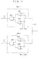
- Fig. 11 is a circuit diagram of energy detectors.
- Fig. 1 shows a first embodiment of a bone mineral content measuring apparatus according to the present invention
- Fig. 2 shows the internal structure of a data analyzer 52.
- An X-ray generating device 10 shown in the above left portion in Fig. 1 is composed of an X-ray generator 12 for generating X-rays having a continuous spectrum and two collimators 14-1, 14-2 for converging X-rays generated by the X-ray generator 12.
- a filtering device 20 is provided between the X-ray generator 12 and a living body Q which is subjected to bone mineral content measurement in this embodiment.
- the filtering device 20 may be disposed between the living body Q and a detecting device 30 for detecting X-rays.
- the filtering device 20 is provided with a plurality of X-ray filters for changing the spectrum of X-rays.
- the plurality of X-ray filters in combination constitute a circular filter disc 22 in this embodiment.
- the filtering device 20 is also provided with a switching device 24 for switching the plurality of X-ray filters and inserting the selected X-ray filter into an X-ray beam path.
- the switching device 24 is composed of a motor or the like in this embodiment.
- the filtering device 20 (in particular, X-ray filters) will be described in detail later.
- X-rays 101 generated by the X-ray generator 12 are converged by the collimator 14-1, subjected to a predetermined spectrum conversion by one of the plurality of X-ray filters which constitute the filter disc 22, further converged by the collimator 14-2 and irradiated onto the living body Q.
- the X-rays pass through the living body Q while being absorbed into the bones or the like in correspondence to the amount of calcium contained therein, and are thereafter detected by the X-ray detecting device 30.
- the detecting device 30 is composed of a plurality of detectors 32 and the same number of preamplifiers 34 provided for the respective detectors 32.
- the detector 32 for example, a semiconductor detector is used.
- 80 channels of X-ray detectors are arranged one-dimensionally or two-dimensionally.
- the X-rays 103 which have reached the detecting device 30 are detected by the detectors 32 and subjected to a predetermined amplification by the preamplifiers 34.
- the output signals of the detecting device 30 are inputted to a counting unit 40.
- the counting unit 40 is composed of a plurality of comparators 42 for comparing the detection signal with a predetermined reference signal (not shown), a plurality of gate circuits 44 for receiving the outputs of the compara tors 42 and a plurality of counters 46 for counting the outputs of the corresponding gate circuit 44.
- a predetermined gate signal 201 for turning ON/OFF the gates is supplied from a later-described control unit 58 to the gate circuit 44.
- the output signals from the X-ray detecting device 30 are first compared with a predetermined reference signal by the comparator 42 so that only signals above a predetermined level are selected to pass therethrough, passed through the gate circuit 44 and then counted by the counter 46.
- a data memory 50 stores the counting data from the counting unit 40 for each X-ray detector 32.
- the X-ray detection data stored in the data memory 50 is read out in accordance with a command from the control unit 58 and transferred to a data analyzer 52.
- the data analyzer 52 calculates the bone mineral content (BMC) and the average bone mineral density (BMD) of the living body Q from the X-ray detection data supplied thereto.
- the results of calculation are supplied to an image forming circuit 54 so as to form an image. This image is displayed by a display unit 56.
- the data analyzer 52 also extracts the data on the soft tissue and the bone region in the living body Q, and the data corresponding to the soft tissue and the bone region are also transferred to the image forming circuit 54.
- the image forming circuit 54 forms a two-dimensional image of the soft tissue and the bone region which have transmitted the X-rays.
- the filtering device 20 is also provided with a rotation detector 26 for detecting the rotational angle of the filter disc 22.
- the detection signal from the rotation detector 26 is supplied to a synchronizing circuit 61, and a synchronizing signal is supplied from the synchronizing circuit 61 to the control unit 58.
- the control unit 58 opens or closes the gate circuits 44 on the basis of the supplied synchronizing signal. The opening/closing operation will be explained later together with the operation of the filter disc 22.
- the control unit 58 controls the movement of the X-ray detecting device 30 in the direction of X or Y through an XY controller 62.
- the control unit 58 also controls the switching (rotating) operation of the filter switching device 24 through a filter controller 64 on the basis of the synchronizing signal.
- the control unit 58 also controls the generation of X-rays of the X-ray generator 12. To state this more practically, the control unit 58 controls the voltage of a high-voltage source 68 through an X-ray controller 66.
- the control unit 58 further controls the movement of the X-ray generator 12 in the direction of X or Y through a movement controller 70.
- a control panel 60 is connected to the control unit 58 and the operator operates the control unit 58 through the control panel 60.
- a bone mineral content is measured by what is called a balanced filter method.
- Fig. 3 shows the principle of a method of obtaining a monochromatic spectrum from a continuous spectrum by using a pair of X-ray filters provided in a bone mineral content measuring apparatus according to the present invention.
- the pair of X-ray filters provided in the apparatus are respectively composed of substances having K-absorption edges at different energy values.
- the K-absorption edge is produced by the photoelectric absorption of X-rays. This phenomenon is produced when X-rays are suddenly absorbed into the K-shell orbit due to the equality of the energy of the X-rays to the ionization energy of the electrons on the K-shell orbit.
- the X-ray absorbing characteristics including the above-described K-absorption edges are indicated by the graphs 303 and 304 in (A2) and (B2).
- the X-ray absorbing characteristic 303 is the X-ray absorbing characteristic of one of the pair of X-ray filters and the X-ray absorbing characteristic 304 is that of the other X-ray filter.
- the X-ray absorbing characteristic 303 has a K-absorption edge Ka and the absorbing characteristic 304 has a K-absorption edge Kb.
- Ka and Kb are caused at the energies which are different from but are approximate to each other.
- the X rays having the spectrum 301 shown in (A1) are absorbed into the one X-ray filter having the X-ray absorbing characteristic 303 shown in (A2), and the spectrum 301 is converted into a spectrum 305 shown in (A3).
- the X rays having the spectrum 302 shown in (B1) are absorbed into the other X-ray filter having the X-ray absorbing characteristic 304 shown in (B2), and the spectrum 302 is converted into a spectrum 306 shown in (B3).
- the difference between the spectrum 305 shown in (A3) and the spectrum 306 shown in (B3) is represented by the region F in the form of a spectrum in (C1).
- the spectra 305 and 306 are obtained as the count values (the hatched portions in (A3) and (B3)) by the counting unit 40, and the difference F is obtained from the difference between the two count values.
- Figs. 4a and 4b show a first example of an X-ray filter, wherein Fig. 4a is a schematic sectional view of the filter disc 22 shown in Fig. 4b, taken along the line IV-IV', and Fig. 4b is a schematic elevational view of the filter disc 22.
- a plurality of X-ray filters are united into one body to constitute the circular filter disc 22, as explained with reference to Fig. 1.
- the filter disc 22 is composed of four sectoral X-ray filters, namely, a pair of X-ray filters F L ⁇ , F Lß for a low energy and a pair of X-ray filters F H ⁇ , F Hß for a high energy.
- Fig. 5 is a list of the substances which constitute the filter disc 22 shown in Fig. 4.
- Gd gallium
- Ce ce
- Pb lead
- Au gold
- the filter disc 22 shown in Fig. 4 is rotated by the filter switching device which is composed of, for example, a motor. By this rotation, the position on the filter disc 22 irradiated with the X-rays is continuously changed, and the spectrum of the X-rays is changed depending upon the substance of the X-ray filter.
- Fig. 6 shows the relationship between the rotation of the filter disc 22 and the gate signal 201.
- the filter disc 22 is rotated at a rotational period ⁇ .
- the rotational period ⁇ is 20 ms.
- the filter disc 22 Since the filter disc 22 is divided into four X-ray filters, the X-rays are transmitted through different substances at intervals of ⁇ /4. In the former half ⁇ /2 of one period ⁇ , since the pair of filters for a low energy are used, measurement is carried out by the X-rays having a low energy, while in the latter half ⁇ /2 of one period ⁇ , since the pair of filters for a high energy are used, measurement is carried out by the X-rays having a high energy.
- the gate signal 201 is supplied from the control unit 58 to the gate circuit 44 in synchronoization with the switching of the X-ray filters.
- the gate circuit 44 is turned on with the rise of the gate signal 201 and turned off with the fall of the gate signal 201.
- the gate signal 201 falls to L0 in about 1 ms during the operation of switching the X-ray filters, as shown in Fig. 6, and the gate circuit 44 is turned off in this period L0.
- the filter disc 22 constantly rotates at a constant angular speed during the measurement of a bone mineral content, while the filters are continuously switched for scanning the living body Q with the X-ray beam.
- Fig. 7 shows a second example of an X-ray filter which is applied to a bone mineral content measuring apparatus according to the present invention, wherein Fig. 7a is a schematic sectional view of a filter disc 28 shown in Fig. 7b, taken along the line VII-VII', and Fig. 7b is a schematic elevational view of the filter disc 28. A plurality of filters are united into one body to constitute the circular filter disc 28.
- the filter disc 28 is composed of four pairs of X-ray filters, namely, a pair of X-ray filters a1, a2 for a high X-ray intensity and a low energy, a pair of X-ray filters b1, b2 for a high X-ray intensity and a high energy, a pair of X-ray filters c1, c2 for a low X-ray intensity and a low energy and a pair of X-ray filters d1, d2 for a low X-ray intensity and a high energy.
- the filter disc 28 is composed of a combination of X-ray filters which corresponds to all the combinations of the intensity and the energy of X-rays.
- the bone mineral content of a region which does not require X-rays is measured by the irradiation of X-rays having a low intensity.
- the bone mineral content is measured by the irradiation of X-rays having a high intensity.
- this example is advantageous in that the bone mineral content measurement is enabled with X-rays having an appropriate intensity in correspondence to the region to be measured.
- the intensity of X-rays are divided into two in this example, it may naturally be divided into three or four.
- the same substances as those shown in Fig. 4 are used for the filters a1, a2, b1 and b2, respectively, and the X-ray filters c1, c2, d1 and d2,are produced by overlaying the respective filter substances shown in Fig. 4 with an X-ray attenuating layer.
- the respective sectoral filter substances are united into one body so as to form a discoidal first filter layer 28a, and the first filter layer 28a is further overlaid with a semicircular second filter layer 28b consisting of an X-ray attenuating substance.
- copper (Cu), brass (Cu + Zn) or the like is preferably used as the X-ray attenuating substance.
- the method of switching the intensities of the X-rays is not restricted thereto.
- two kinds of X-ray filters having different thicknesses may be provided so as to switch the intensities of the X-rays.
- an X-ray attenuating filter may be disposed independently in the X-ray beam path.
- the thicknesses of the Gd, Ce and Pb filters are 0.512 mm, 0.756 mm and 0.685 mm, respectively, and the thickness of the X-ray attenuating layer is about 1.0 mm.
- the thicknesses of the Gd, Ce and Pb filters are 0.256 mm, 0.378 mm and 0.852 mm, respectively, and the X-ray attenuating layer is a composition of copper having a thickness of 0.2 mm and brass having a thickness of 0.8 mm.
- Fig. 8 shows the relationship between the rotation of the filter disc 28 and the gate signal 201.
- a pair of X-ray filters for a high energy and a pair of X-ray filters for a low energy are switched over each other, and at intervals of ⁇ /8, the current X-ray filter is switched over the subsequent X-ray filter.
- the gate signal 201 supplied from the control unit 58 to the gate circuit 44 forms a wave form in synchronization with the switching of the filters. In this way, the gate signal 201 prevents the border of the X-ray filters from being irradiated with the X-ray beam at the time of switching the filters which would lead to the deterioration of the accuracy of the X-ray detection data.
- the second example of the X-ray filter is rotated, for example, at a rotational period of 40 ms for the measurement of the whole body and at a rotational period of 400 ms for the measurement of the bone mineral content of the lumbar or the cerebrum. It is naturally preferable to vary the rotational period in accordance with the region of the living body to be measured.
- the X-ray filter is discoidal in the above examples, but the configuration is naturally not restricted thereto and may be different.
- Fig. 2 shows a block diagram of the data analyzer 52 shown in Fig. 1.
- the X-ray detection data are inputted from the data memory 50 to two subtracters 72-1, 72-2.
- Data I L ⁇ , I Lß obtained by using the pair of X-ray filters for a low energy are inputted to the subtracter 72-1, and data I H ⁇ , I Hß obtained by using the pair of X-ray filters for a high energy are inputted to the subtracter 72-2. It is naturally possible to subsequently obtain the difference between the data from the measurement with a high energy and the difference between the data from the measurement with a low energy by one subtracter.
- the subtracters 72-1, 72-2 execute the following calculations: wherein ⁇ I L and ⁇ I H are the above described differences. These differences represent the region F shown in (C1) of Fig. 3.
- the computer 74 solves the following simultaneous equations to obtain the thickness X B of the bone and the thickness X S of the soft tissue along the X-ray beam: wherein wherein ⁇ I L0 and ⁇ I H0 are the initial differences between the spectra of the X-rays having a low energy and between the spectra of the X-rays having a high energy, respective-ly, which are not transmitted through the living body.
- ⁇ LB , ⁇ LS , ⁇ HB and ⁇ HS are the X-ray absorption coefficients (cm -1 ) of the bone and the soft tissue, respectively, with respect to X-rays having a high energy and a low energy, respectively.
- the thickness X B (cm) of the bone and the thickness X S (cm) of the soft tissue are obtained.
- X B obtained is inputted to a bone mineral content analyzing circuit 76 and X B in the direction of X and X B in the direction of Y are accumulated.
- the accumulated value is multiplied by a predetermined coefficient to obtain the bone mineral content (BMC), as follows: wherein ⁇ B represents the density (g/cm3) of the bone and ⁇ 5 represents the element area (cm2).
- the output X B of the computer 74 is inputted to a bone area calculator 78.
- the bone area calculator 78 obtains the area of the bone by extracting the data on the X-rays which have passed through the bone region in the living body from the X-ray detection data.
- the X-ray detection data from each channel of the detector 32 is compared with a predetermined threshold value and the area A of the bone is obtained from the number of the channels which have the X-ray detection data exceeding the threshold value.
- Both the data on the area A from the bone area calculator 78 and the data on the bone mineral content BMC from the bone mineral content analyzing circuit 76 are inputted to an average bone mineral density analyzing circuit 79.
- the average bone mineral density circuit 79 obtains the average bone mineral density BMD by dividing the bone mineral content BMC by the bone area A obtained in the above described way.
- the thus-obtained BMD, BMC, X B and K S are supplied to the image forming circuit 54 shown in Fig. 1.
- the image forming circuit 54 forms a two-dimensional image of the living body which has transmitted the X-rays by using K B and K S .
- K B and K S it is preferable to express the bone mineral content of each region by a hue and display an image obtained by the composition of each region.
- a bone mineral content measuring apparatus of this embodiment since X-ray filters having X-ray absorbing characteristics with the K-absorption edges at different energy values are used, it is possible to measure a bone mineral content easily without converting the continuous spectrum of the X-rays generated by the X-ray generating device into a monochromatic spectrum.
- Fig. 9 shows a second embodiment of a bone mineral content measuring apparatus according to the present invention.
- An X-ray generating device 80 generates X-rays having a continuous spectrum.
- the X-rays generated are subjected to a predetermined spectrum conversion by an X-ray filter 82.
- the X-ray filter 82 is composed of a substance having an X-ray absorbing characteristic with the K-absorption edge at a predetermined energy value.
- the X-rays which have passed through the X-ray filter 82 are absorbed into the living body Q in correspondence to the bone mineral content and thereafter detected by an X-ray detecting device 84.
- the X-ray detecting device 84 is composed of, for example, semiconductor detectors which are arranged one-dimensionally or two-dimensionally.
- the spectrum 321 of the X-rays generated by the X-ray generating device 80 is shown in (A).
- the abscissa E represents the energy of the X-rays and the ordinate I represents the intensity of the X-rays.
- the X-rays having the spectrum 321 are subjected to a predetermined absorption by the X-ray filter 82.
- the X-ray absorbing characteristic 322 of the X-ray filter 82 is shown in (B).
- the abscissa E represents the energy of the X-rays and the ordinate ⁇ represents the X-ray absorption coefficient.
- the X-ray filter 82 is composed of a substance having an X-ray absorbing characteristic with the K-absorption edge at a predetermined energy value.
- the K-absorption edge K ⁇ is shown in (B).
- the spectrum 321 having one peak is converted to a spectrum 323 having two peaks with the trough in the vicinity of the K-absorption edge K ⁇ , as shown in (C).
- the bone mineral content is measured by using the characteristic of the spectrum having two peaks.
- the measurement of a bone mineral content similar to the measurement of a bone mineral content using two X-rays having monochromatic spectra and different energies is carried out by using the spectrum 323 having two peaks.
- the detection signal from the X-ray detecting device 84 is inputted to a preamplifier 86 for a predetermined amplification.
- the amplified detection signal is supplied to a low energy detector 88-1 and a high energy detector 88-2.
- Predetermined threshold value signals E1 , E2 are supplied from a threshold value setting device 92 to the low energy detector 88-1, and predetermined threshold value signals E3, E4 are supplied from the threshold value setting device 92 to the high energy detector 88-2.
- Fig. 11 is a circuit diagram of the low energy detector 88-1 and the high energy detector 88-2.
- the low energy detector 88-1 is composed of two comparators 401, 402 for the upper limit and the lower limit, respectively, for comparing a detection signal 210 with the threshold signals and an AND gate 403 for inputting the outputs of the two comparators 401, 402.
- the high energy detector 88-2 is composed of two comparators 404, 405 and an AND gate 406, in the same way as in the low energy detector 88-1.
- the output signals from the respective energy detectors 88 are supplied to counters 89-1 and 89-2 for counting.
- a bone mineral content analyzing circuit 90 inputs the outputs of the counters 89-1, 89-2, and calculates the bone mineral content on the basis of the count value in the specified low energy region ⁇ E12 and the count value in the specified high energy region ⁇ E34.
- the bone mineral content obtained is input to a display unit 94 for a predetermined display.
- the bone mineral content measuring apparatus of this embodiment since the X-ray filter is composed of a substance having the K-absorption edge at a predetermined energy value, it is possible to measure the bone mineral content in the same way as in the case of using two X-rays having monochromatic spectra. Thus, it is possible to realize a bone mineral content measuring apparatus having a simple structure.
- This embodiment is advantageous especially in that since the measurement with X-rays in a low energy region and the measurement with X-rays in a high energy region can be simultaneously carried out, the swift bone mineral content measurement is enabled.
- the position of the X-ray filter 82 between the X-ray generating device 80 and the living body Q is not essential, and the X-ray filter 82 may be disposed between the living body Q and the X-ray detecting device 84.
- the substances such as those shown in Fig. 5 are used for the X-ray filters.
Applications Claiming Priority (9)
| Application Number | Priority Date | Filing Date | Title |
|---|---|---|---|
| JP32495489 | 1989-12-14 | ||
| JP1324954A JPH03185344A (ja) | 1989-12-14 | 1989-12-14 | X線を用いた成分分析方法及び装置 |
| JP32495589 | 1989-12-14 | ||
| JP1324955A JPH03185345A (ja) | 1989-12-14 | 1989-12-14 | X線を用いた成分分析方法 |
| JP324955/89 | 1989-12-14 | ||
| JP324954/89 | 1989-12-14 | ||
| JP332279/89 | 1989-12-20 | ||
| JP1332279A JPH03191850A (ja) | 1989-12-20 | 1989-12-20 | X線を用いた成分分析装置 |
| JP33227989 | 1989-12-20 |
Publications (3)
| Publication Number | Publication Date |
|---|---|
| EP0432730A2 true EP0432730A2 (de) | 1991-06-19 |
| EP0432730A3 EP0432730A3 (en) | 1992-03-18 |
| EP0432730B1 EP0432730B1 (de) | 1999-08-04 |
Family
ID=27340084
Family Applications (1)
| Application Number | Title | Priority Date | Filing Date |
|---|---|---|---|
| EP90123814A Expired - Lifetime EP0432730B1 (de) | 1989-12-14 | 1990-12-11 | Vorrichtung zur Messung des Kalziumgehaltes von Knochen |
Country Status (3)
| Country | Link |
|---|---|
| US (1) | US5204888A (de) |
| EP (1) | EP0432730B1 (de) |
| DE (1) | DE69033232T2 (de) |
Cited By (14)
| Publication number | Priority date | Publication date | Assignee | Title |
|---|---|---|---|---|
| DE4137055A1 (de) * | 1991-11-11 | 1993-05-19 | Heimann Gmbh | Scanner zur untersuchung von pruefobjekten |
| EP0713676A3 (de) * | 1994-11-25 | 1996-11-06 | Hologic Inc | Dichtemessung von Knochen mittels Röntgenstrahlung |
| EP0747008A1 (de) * | 1995-06-07 | 1996-12-11 | Hologic, Inc. | Gerät zur Dichtemessung von Knochen mittels Röntgenstrahlung |
| US5687211A (en) * | 1993-11-22 | 1997-11-11 | Hologic, Inc. | Bone densitometry scanning system and method for selecting scan parametric values using x-ray thickness measurement |
| US5717735A (en) * | 1993-11-22 | 1998-02-10 | Hologic, Inc. | Medical radiological apparatus including optical crosshair device for patient positioning and forearm and spinal positioning aides |
| US5715820A (en) * | 1995-06-06 | 1998-02-10 | Hologic, Inc. | X-ray bone densitometry using multiple pass scanning with image blending |
| US5748705A (en) * | 1993-11-22 | 1998-05-05 | Hologic Inc. | X-ray bone densitometry |
| US5809104A (en) * | 1995-01-12 | 1998-09-15 | Kullenberg; Ragnar | Method and device for measuring the content of bone mineral in the skeleton |
| US5838765A (en) * | 1993-11-22 | 1998-11-17 | Hologic, Inc. | Whole-body x-ray bone densitometry using a narrow-angle fan beam, including variable fan beam displacement between scan passes |
| EP0963549A1 (de) * | 1997-02-03 | 1999-12-15 | Hologic, Inc. | Knochendichtemessung mittels röntgerabbildungsvorrichtungen |
| US6059455A (en) * | 1993-11-22 | 2000-05-09 | Hologic, Inc. | Portable X-ray bone densitometry system |
| US6217214B1 (en) | 1993-11-22 | 2001-04-17 | Hologic, Inc. | X-ray bone densitometry apparatus |
| FR2832021A1 (fr) * | 2001-11-08 | 2003-05-09 | Ge Med Sys Global Tech Co Llc | Techniques d'imagerie a rayons x a energie multiple |
| EP2591728A1 (de) * | 2011-11-14 | 2013-05-15 | Samsung Electronics Co., Ltd | Computertomographievorrichtung und Steuerungsverfahren dafür |
Families Citing this family (20)
| Publication number | Priority date | Publication date | Assignee | Title |
|---|---|---|---|---|
| JP2962015B2 (ja) * | 1991-02-20 | 1999-10-12 | 松下電器産業株式会社 | k吸収端フィルタおよびX線装置 |
| DE4215343A1 (de) * | 1992-05-09 | 1993-11-11 | Philips Patentverwaltung | Filterverfahren für ein Röntgensystem und Anordnung zur Durchführung eines solchen Filterverfahrens |
| US5931780A (en) * | 1993-11-29 | 1999-08-03 | Arch Development Corporation | Method and system for the computerized radiographic analysis of bone |
| US5585603A (en) * | 1993-12-23 | 1996-12-17 | Design Systems, Inc. | Method and system for weighing objects using X-rays |
| WO1997024069A1 (en) * | 1995-12-26 | 1997-07-10 | Holomed Aps | A method and system for generating an x-ray image |
| JP3363735B2 (ja) * | 1996-06-26 | 2003-01-08 | 松下電器産業株式会社 | X線画像装置 |
| US6252928B1 (en) | 1998-01-23 | 2001-06-26 | Guard Inc. | Method and device for estimating bone mineral content of the calcaneus |
| US6269144B1 (en) | 1998-03-04 | 2001-07-31 | William P. Dube | Method and apparatus for diffraction measurement using a scanning x-ray source |
| US6418193B1 (en) * | 1999-11-01 | 2002-07-09 | General Electric Company | Imaging system including radiation filter for x-ray imaging |
| US6614878B2 (en) * | 2001-01-23 | 2003-09-02 | Fartech, Inc. | X-ray filter system for medical imaging contrast enhancement |
| US7120222B2 (en) * | 2003-06-05 | 2006-10-10 | General Electric Company | CT imaging system with multiple peak x-ray source |
| CN101074937B (zh) * | 2006-05-19 | 2010-09-08 | 清华大学 | 能谱调制装置、识别材料的方法和设备及图像处理方法 |
| US7430274B2 (en) * | 2007-02-27 | 2008-09-30 | Innov-X-Systems, Inc. | XRF analyzer |
| JP2011067333A (ja) * | 2009-09-25 | 2011-04-07 | Fujifilm Corp | 放射線画像撮影装置及び撮影制御装置 |
| WO2014171487A1 (ja) * | 2013-04-16 | 2014-10-23 | 株式会社 東芝 | X線ct装置 |
| JP2015180859A (ja) * | 2014-03-05 | 2015-10-15 | 株式会社東芝 | フォトンカウンティングct装置 |
| US9991014B1 (en) * | 2014-09-23 | 2018-06-05 | Daniel Gelbart | Fast positionable X-ray filter |
| CN105433973B (zh) * | 2015-12-30 | 2018-09-18 | 沈阳东软医疗系统有限公司 | Ct扫描设备、ct系统和控制过滤器组件的方法及装置 |
| US10525286B2 (en) * | 2017-05-18 | 2020-01-07 | Wisconsin Alumni Research Foundation | Compact sharpening filter for orthovoltage x-rays |
| JP7112343B2 (ja) * | 2019-01-28 | 2022-08-03 | 富士フイルムヘルスケア株式会社 | 医療用x線測定装置及びプログラム |
Citations (4)
| Publication number | Priority date | Publication date | Assignee | Title |
|---|---|---|---|---|
| US3435220A (en) * | 1965-02-26 | 1969-03-25 | Industrial Nucleonics Corp | Dual channel radiation gauge for identifying material components |
| US3715588A (en) * | 1970-10-26 | 1973-02-06 | Norland Corp | Bone mineral analyzer |
| EP0168090A1 (de) * | 1984-06-19 | 1986-01-15 | B.V. Optische Industrie "De Oude Delft" | Vorrichtung zum Nachweis von zwei Röntgenstrahlenergien |
| JPH01196551A (ja) * | 1988-01-31 | 1989-08-08 | Shimadzu Corp | 骨塩定量分析装置 |
Family Cites Families (7)
| Publication number | Priority date | Publication date | Assignee | Title |
|---|---|---|---|---|
| US3974386A (en) * | 1974-07-12 | 1976-08-10 | Wisconsin Alumni Research Foundation | Differential X-ray method and apparatus |
| US4686695A (en) * | 1979-02-05 | 1987-08-11 | Board Of Trustees Of The Leland Stanford Junior University | Scanned x-ray selective imaging system |
| US4528685A (en) * | 1983-05-16 | 1985-07-09 | General Electric Company | X-ray beam filter device |
| US4811373A (en) * | 1986-07-14 | 1989-03-07 | Hologic, Inc. | Bone densitometer |
| US5040199A (en) * | 1986-07-14 | 1991-08-13 | Hologic, Inc. | Apparatus and method for analysis using x-rays |
| JPH0196551A (ja) * | 1987-10-08 | 1989-04-14 | Shimadzu Corp | 電気泳動による試料の分取方法 |
| JPH0659280B2 (ja) * | 1989-04-19 | 1994-08-10 | 松下電器産業株式会社 | X線画像処理装置 |
-
1990
- 1990-12-11 DE DE69033232T patent/DE69033232T2/de not_active Expired - Lifetime
- 1990-12-11 EP EP90123814A patent/EP0432730B1/de not_active Expired - Lifetime
- 1990-12-14 US US07/628,619 patent/US5204888A/en not_active Expired - Lifetime
Patent Citations (4)
| Publication number | Priority date | Publication date | Assignee | Title |
|---|---|---|---|---|
| US3435220A (en) * | 1965-02-26 | 1969-03-25 | Industrial Nucleonics Corp | Dual channel radiation gauge for identifying material components |
| US3715588A (en) * | 1970-10-26 | 1973-02-06 | Norland Corp | Bone mineral analyzer |
| EP0168090A1 (de) * | 1984-06-19 | 1986-01-15 | B.V. Optische Industrie "De Oude Delft" | Vorrichtung zum Nachweis von zwei Röntgenstrahlenergien |
| JPH01196551A (ja) * | 1988-01-31 | 1989-08-08 | Shimadzu Corp | 骨塩定量分析装置 |
Non-Patent Citations (3)
| Title |
|---|
| MEDICAL AND BIOLOGICAL ENGINEERING. vol. 12, no. 1, January 1974, STEVENAGE GB pages 113 - 119; GUSTAFSSON ET AL.: 'X RAY SPECTROPHOTOMETRY FOR BONE-MINERAL DETERMINATIONS' * |
| MEDICAL PHYSICS. vol. 3, no. 3, 1976, NEW YORK US pages 159 - 168; KELCZ ET AL.: 'ABSORPTION-EDGE FLUOROSCOPY USING A THREE-SPECTRUM TECHNIQUE' * |
| PATENT ABSTRACTS OF JAPAN vol. 13, no. 492 (P-955)(3840) 8 November 1989 & JP-A-1 196 551 ( SHIMADZU ) 8 August 1989 * |
Cited By (20)
| Publication number | Priority date | Publication date | Assignee | Title |
|---|---|---|---|---|
| DE4137055A1 (de) * | 1991-11-11 | 1993-05-19 | Heimann Gmbh | Scanner zur untersuchung von pruefobjekten |
| US6059455A (en) * | 1993-11-22 | 2000-05-09 | Hologic, Inc. | Portable X-ray bone densitometry system |
| US6009147A (en) * | 1993-11-22 | 1999-12-28 | Hologic, Inc. | X-ray bone densitometry |
| US5835562A (en) * | 1993-11-22 | 1998-11-10 | Hologic, Inc. | Medical radiological apparatus including optical crosshair device for patient positioning and forearm and spinal positioning aides |
| US5717735A (en) * | 1993-11-22 | 1998-02-10 | Hologic, Inc. | Medical radiological apparatus including optical crosshair device for patient positioning and forearm and spinal positioning aides |
| US6217214B1 (en) | 1993-11-22 | 2001-04-17 | Hologic, Inc. | X-ray bone densitometry apparatus |
| US5748705A (en) * | 1993-11-22 | 1998-05-05 | Hologic Inc. | X-ray bone densitometry |
| US5771272A (en) * | 1993-11-22 | 1998-06-23 | Hologic, Inc. | X-ray densitometer detector calibration by beam flattening and continuous dark scanning |
| US5778045A (en) * | 1993-11-22 | 1998-07-07 | Hologic, Inc. | Single/dual-energy x-ray densitometry scanning, including operator selected scanning sequences |
| US5687211A (en) * | 1993-11-22 | 1997-11-11 | Hologic, Inc. | Bone densitometry scanning system and method for selecting scan parametric values using x-ray thickness measurement |
| US5835555A (en) * | 1993-11-22 | 1998-11-10 | Hologic, Inc. | X-ray bone densitometry apparatus with variable attenuation, modulation and collimation of penetrating radiation beam |
| US5838765A (en) * | 1993-11-22 | 1998-11-17 | Hologic, Inc. | Whole-body x-ray bone densitometry using a narrow-angle fan beam, including variable fan beam displacement between scan passes |
| EP0713676A3 (de) * | 1994-11-25 | 1996-11-06 | Hologic Inc | Dichtemessung von Knochen mittels Röntgenstrahlung |
| US5809104A (en) * | 1995-01-12 | 1998-09-15 | Kullenberg; Ragnar | Method and device for measuring the content of bone mineral in the skeleton |
| US5715820A (en) * | 1995-06-06 | 1998-02-10 | Hologic, Inc. | X-ray bone densitometry using multiple pass scanning with image blending |
| EP0747008A1 (de) * | 1995-06-07 | 1996-12-11 | Hologic, Inc. | Gerät zur Dichtemessung von Knochen mittels Röntgenstrahlung |
| EP0963549A1 (de) * | 1997-02-03 | 1999-12-15 | Hologic, Inc. | Knochendichtemessung mittels röntgerabbildungsvorrichtungen |
| EP0963549A4 (de) * | 1997-02-03 | 2002-04-10 | Hologic Inc | Knochendichtemessung mittels röntgerabbildungsvorrichtungen |
| FR2832021A1 (fr) * | 2001-11-08 | 2003-05-09 | Ge Med Sys Global Tech Co Llc | Techniques d'imagerie a rayons x a energie multiple |
| EP2591728A1 (de) * | 2011-11-14 | 2013-05-15 | Samsung Electronics Co., Ltd | Computertomographievorrichtung und Steuerungsverfahren dafür |
Also Published As
| Publication number | Publication date |
|---|---|
| DE69033232D1 (de) | 1999-09-09 |
| EP0432730A3 (en) | 1992-03-18 |
| EP0432730B1 (de) | 1999-08-04 |
| DE69033232T2 (de) | 1999-12-30 |
| US5204888A (en) | 1993-04-20 |
Similar Documents
| Publication | Publication Date | Title |
|---|---|---|
| US5204888A (en) | Bone mineral content measuring apparatus | |
| JP4949664B2 (ja) | Ctコロノグラフィ・システム | |
| US4686695A (en) | Scanned x-ray selective imaging system | |
| US4768214A (en) | Imaging | |
| US5040199A (en) | Apparatus and method for analysis using x-rays | |
| JP4831556B2 (ja) | 複数ピークのx線源を具備するctイメージングシステム | |
| EP2002287B1 (de) | Dynamische optimierung des signal- rausch-verhältnisses von doppelenergie-dämpfungsdaten für die rekonstruierung von bildern | |
| US4442489A (en) | Device for computed tomography | |
| US7697657B2 (en) | System and method of density and effective atomic number imaging | |
| JP5703014B2 (ja) | サンプリングレートを低減した2重エネルギー撮像 | |
| US7031425B2 (en) | Methods and apparatus for generating CT scout images | |
| US8396273B2 (en) | Noise reduction method for dual-energy imaging | |
| EP0123276A2 (de) | Röntgendiagnostikgerät | |
| JPH06508290A (ja) | 改良されたx線容積測定ctスキャナー | |
| WO2008075595A1 (ja) | X線ct装置 | |
| US20110150175A1 (en) | Apparatus and method for spectral projection imaging with fast kv switching | |
| EP1384440A2 (de) | Verfahren und Vorrichtung zur Computer-Tomographie | |
| EP0594840B1 (de) | Anordnung zur selektiven abbildung von materialen | |
| US4081681A (en) | Treatment of absorption errors in computerized tomography | |
| JPH06121791A (ja) | X線定量装置およびx線定量方法 | |
| US20040120457A1 (en) | Scatter reducing device for imaging | |
| GB2088670A (en) | Radiation absorption distribution measurement in a part section of a body | |
| US6389097B1 (en) | Multi-plate volumetric CT scanner gap compensation method and apparatus | |
| KR101521837B1 (ko) | 엑스선 데이터 획득 시스템 | |
| JPH04263842A (ja) | Dexa機能を持つct装置 |
Legal Events
| Date | Code | Title | Description |
|---|---|---|---|
| PUAI | Public reference made under article 153(3) epc to a published international application that has entered the european phase |
Free format text: ORIGINAL CODE: 0009012 |
|
| AK | Designated contracting states |
Kind code of ref document: A2 Designated state(s): DE FR GB IT |
|
| PUAL | Search report despatched |
Free format text: ORIGINAL CODE: 0009013 |
|
| AK | Designated contracting states |
Kind code of ref document: A3 Designated state(s): DE FR GB IT |
|
| 17P | Request for examination filed |
Effective date: 19920511 |
|
| 17Q | First examination report despatched |
Effective date: 19940705 |
|
| GRAG | Despatch of communication of intention to grant |
Free format text: ORIGINAL CODE: EPIDOS AGRA |
|
| GRAG | Despatch of communication of intention to grant |
Free format text: ORIGINAL CODE: EPIDOS AGRA |
|
| GRAH | Despatch of communication of intention to grant a patent |
Free format text: ORIGINAL CODE: EPIDOS IGRA |
|
| GRAH | Despatch of communication of intention to grant a patent |
Free format text: ORIGINAL CODE: EPIDOS IGRA |
|
| GRAA | (expected) grant |
Free format text: ORIGINAL CODE: 0009210 |
|
| AK | Designated contracting states |
Kind code of ref document: B1 Designated state(s): DE FR GB IT |
|
| REF | Corresponds to: |
Ref document number: 69033232 Country of ref document: DE Date of ref document: 19990909 |
|
| ITF | It: translation for a ep patent filed |
Owner name: STUDIO JAUMANN P. & C. S.N.C. |
|
| ET | Fr: translation filed | ||
| PLBE | No opposition filed within time limit |
Free format text: ORIGINAL CODE: 0009261 |
|
| STAA | Information on the status of an ep patent application or granted ep patent |
Free format text: STATUS: NO OPPOSITION FILED WITHIN TIME LIMIT |
|
| 26N | No opposition filed | ||
| REG | Reference to a national code |
Ref country code: GB Ref legal event code: IF02 |
|
| PGFP | Annual fee paid to national office [announced via postgrant information from national office to epo] |
Ref country code: FR Payment date: 20091216 Year of fee payment: 20 Ref country code: GB Payment date: 20091209 Year of fee payment: 20 |
|
| PGFP | Annual fee paid to national office [announced via postgrant information from national office to epo] |
Ref country code: IT Payment date: 20091229 Year of fee payment: 20 |
|
| PGFP | Annual fee paid to national office [announced via postgrant information from national office to epo] |
Ref country code: DE Payment date: 20091228 Year of fee payment: 20 |
|
| REG | Reference to a national code |
Ref country code: GB Ref legal event code: PE20 Expiry date: 20101210 |
|
| PG25 | Lapsed in a contracting state [announced via postgrant information from national office to epo] |
Ref country code: GB Free format text: LAPSE BECAUSE OF EXPIRATION OF PROTECTION Effective date: 20101210 |
|
| PG25 | Lapsed in a contracting state [announced via postgrant information from national office to epo] |
Ref country code: DE Free format text: LAPSE BECAUSE OF EXPIRATION OF PROTECTION Effective date: 20101211 |