EP0431615A2 - Récipient - Google Patents
Récipient Download PDFInfo
- Publication number
- EP0431615A2 EP0431615A2 EP90123435A EP90123435A EP0431615A2 EP 0431615 A2 EP0431615 A2 EP 0431615A2 EP 90123435 A EP90123435 A EP 90123435A EP 90123435 A EP90123435 A EP 90123435A EP 0431615 A2 EP0431615 A2 EP 0431615A2
- Authority
- EP
- European Patent Office
- Prior art keywords
- adapter
- shutter
- site
- cartridge
- cartridge unit
- Prior art date
- Legal status (The legal status is an assumption and is not a legal conclusion. Google has not performed a legal analysis and makes no representation as to the accuracy of the status listed.)
- Granted
Links
Images


Classifications
-
- G—PHYSICS
- G03—PHOTOGRAPHY; CINEMATOGRAPHY; ANALOGOUS TECHNIQUES USING WAVES OTHER THAN OPTICAL WAVES; ELECTROGRAPHY; HOLOGRAPHY
- G03G—ELECTROGRAPHY; ELECTROPHOTOGRAPHY; MAGNETOGRAPHY
- G03G15/00—Apparatus for electrographic processes using a charge pattern
- G03G15/06—Apparatus for electrographic processes using a charge pattern for developing
- G03G15/08—Apparatus for electrographic processes using a charge pattern for developing using a solid developer, e.g. powder developer
- G03G15/0822—Arrangements for preparing, mixing, supplying or dispensing developer
- G03G15/0877—Arrangements for metering and dispensing developer from a developer cartridge into the development unit
- G03G15/0881—Sealing of developer cartridges
- G03G15/0886—Sealing of developer cartridges by mechanical means, e.g. shutter, plug
-
- G—PHYSICS
- G03—PHOTOGRAPHY; CINEMATOGRAPHY; ANALOGOUS TECHNIQUES USING WAVES OTHER THAN OPTICAL WAVES; ELECTROGRAPHY; HOLOGRAPHY
- G03G—ELECTROGRAPHY; ELECTROPHOTOGRAPHY; MAGNETOGRAPHY
- G03G15/00—Apparatus for electrographic processes using a charge pattern
- G03G15/06—Apparatus for electrographic processes using a charge pattern for developing
- G03G15/08—Apparatus for electrographic processes using a charge pattern for developing using a solid developer, e.g. powder developer
- G03G15/0822—Arrangements for preparing, mixing, supplying or dispensing developer
- G03G15/0848—Arrangements for testing or measuring developer properties or quality, e.g. charge, size, flowability
- G03G15/0849—Detection or control means for the developer concentration
- G03G15/0855—Detection or control means for the developer concentration the concentration being measured by optical means
-
- G—PHYSICS
- G03—PHOTOGRAPHY; CINEMATOGRAPHY; ANALOGOUS TECHNIQUES USING WAVES OTHER THAN OPTICAL WAVES; ELECTROGRAPHY; HOLOGRAPHY
- G03G—ELECTROGRAPHY; ELECTROPHOTOGRAPHY; MAGNETOGRAPHY
- G03G15/00—Apparatus for electrographic processes using a charge pattern
- G03G15/06—Apparatus for electrographic processes using a charge pattern for developing
- G03G15/08—Apparatus for electrographic processes using a charge pattern for developing using a solid developer, e.g. powder developer
- G03G15/0822—Arrangements for preparing, mixing, supplying or dispensing developer
- G03G15/0865—Arrangements for supplying new developer
Definitions
- the present invention relates to a cartridge unit for containing toner powder and adapted to a developer of a copying machine etc. to supply toner powder.
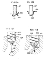
- FIG. 15A One type of conventional toner cartridges is shown in the Japanese Published Unexamined Utility Model Application No. S60-145452, whose structure is illustrated in Fig. 15A.
- the mouth of the toner cartridge 201 is closed by a seal member 202, and an extension of the seal member 202 is folded back.
- the end of the extension is hooked by a pin 204 provided near the entrance of the toner hopper 3, as shown in Fig. 15B.
- the seal member 202 As the cartridge 201 is pushed down the entrance of the toner hopper 203, the seal member 202 is deprived from the mouth and the toner powder in the cartridge 201 falls down to the toner hopper 203.
- FIG. 16A Another example is shown in the Japanese Published Unexamined Utility Model Application No. S59-9364, whose structure is illustrated in Fig. 16A.
- the mouth of a toner cartridge 205 is sealed by a plug 208.
- the toner cartridge 205 is attached to the toner hopper 207 by a male screw 206 formed on the outside surface of the cartridge body and a female screw formed on the inside surface of the entrance of the toner hopper 207.
- On a shelf provided at a midway of the hopper entrance stands a thrust rod 209. As the cartridge body is screwed down the entrance of the hopper 207, the thrust rod 209 pushes up the plug 208 and opens the mouth.
- An object of the present invention is to solve such problems and provide a cartridge unit that can assuredly contain powder (e.g., toner powder for a copying machine, etc.) and prevents unintentional spill-out of the powder.
- powder e.g., toner powder for a copying machine, etc.
- Another object of the present invention is to provide a shutter for the cartridge that surely locks while the cartridge is not attached to a powder receiver (such as a toner hopper) but is easily and automatically released when the cartridge is attached to the powder receiver.
- a powder receiver such as a toner hopper
- Still another object of the present invention is to keep the outside of the cartridge unit always clean even after the cartridge is used to supply toner powder to the toner hopper.
- cartridge unit of the present invention which comprises:
- an adapter fixed to the mouth of the cartridge and having a hole through which the powder is supplied and a slit engraved from a side end of the adapter across the hole, the adapter being attachable to the powder receiver;
- an outer shutter that can be attached on the outside of the adapter for covering the hole of the adapter.
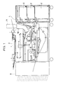
- Fig. 1 is an inside view of a copying machine that a toner cartridge as an embodiment of the present invention is attached.
- Fig. 2A is a perspective view of a hopper shutter
- Fig. 2B is a perspective view of the entrance of the toner hopper of the copying machine
- Fig. 2C show the detail of a notch formed at the front end of the hopper shutter shown in Fig.2A
- Fig.2D show the detail of a claw placed on a supplying site of the toner hopper entrance shown in Fig.2B.
- Fig.3 is a perspective view of the toner cartridge with an adapter.
- Fig.4A is a perspective view of the toner cartridge
- Fig.4B is a perspective view of the adapter as detached from the cartridge
- Fig.4C is a perspective view of the reverse side of the adapter shown in Fig.4B.
- Fig.5 is a perspective view of an inner shutter of the adapter.
- Fig.6 is a perspective view of an outer shutter of the adapter.
- Fig.7 is a plan view of the hopper entrance as the cartridge/adapter unit is placed at a preparation site.
- Fig.8 is a cross-sectional view of the hopper entrance and the cartridge/adapter unit before the unit is placed on the preparation site.
- Fig.9A is a cross-sectional view of the hopper entrance and the cartridge/adapter unit when the unit is placed on the preparation site
- Fig.9B shows the detail of a hook 126 and a table 105 when the hook 126 is pushed up by the table 105
- Fig.9C shows the detail of a leader 1212, claw 107 and a notch when the claw 107 engages with the notch
- Fig.9D shows the detail when the claw 107 is pushed down by the leader 1212 and is disengaged from the notch.
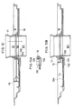
- Fig.10 is a cross-sectional view of the hopper entrance and the cartridge/adapter unit when the unit is being moved from the preparation site to the supplying site.
- Fig.11 is a cross-sectional view of the hopper entrance and the cartridge/adapter unit when the unit is placed at the supplying site.
- Fig.12 is a cross-sectional view of the hopper entrance and the cartridge/adapter unit when the unit is placed at the supplying site and the inner shutter is drawn out to supply toner powder to the toner hopper.
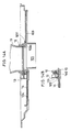
- Fig.13A shows the detail of a cantilever 145, foot 132 and recess 129 when the cantilever 145 engages with the recess 129
- Fig. 13B is a cross-sectional view of the hopper entrance and the cartridge/adapter unit when the unit is placed at the supplying site and the inner shutter returns to the shutting position.
- Fig. 14A is a cross-sectional view of the hopper entrance and the cartridge/adapter unit when the unit is being moved from the supplying site to the preparation site
- Fig. 14B shows the detail of a handle of the inner shutter 13, the hook 126 and a rear notch 146 when the hook 126 locks the inner shutter 13.
- Fig.15A is a cross-sectional view of a conventional toner cartridge before the seal is broken, and Fig.15B shows after the seal is broken.
- Fig.16A is a cross-sectional view of another conventional toner cartridge before it is completely attached to the toner hopper, and Fig.16B shows after it is completely attached.
- An embodiment of the toner cartridge unit of the present invention is used in a copying machine as shown in Fig. 1.
- the copying machine is equipped with: an automatic document handler 3 on the top of the housing 1; a paper supplier boxes 2 at the right side of the housing 1; and a sorter 9 at the left side of the housing 1.
- Inside of the housing 1 is provided: an optical system 4 for reading an original; a photoconductive drum 5 for producing an electrostatic latent image of the original; a developer unit 6 for developing the latent image into a toner powder image; a transferor 7 for transferring the toner image on the drum 5 to a sheet of paper; and a fuser 8 for heat-fixing the toner image on the paper sheet.
- a toner hopper 10 is provided above the developer unit 6 to supply toner powder to the developer unit 6.
- the toner hopper 10 is high enough to reach the upper deck of the housing 1.
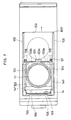
- Fig. 2B shows the entrance of the toner hopper 10.
- a circular hole 101 at the center of the hopper entrance is for admitting the toner powder.
- a guide rail 102 an embodiment of the tenth member
- a hopper shutter 103 as shown in Fig.2A slides on the guide rails 102 to shut the hole 101.
- a stiff edge 103a is formed at either lateral edge of the shutter 103 to slide on the rail 102 and the shutter 103 moves as shown by the arrow S.
- At the front left in Fig.
- the whole hopper entrance is normally closed by a cover 105.
- the above-mentioned members are made of plastics.
- the toner cartridge adaptable to the toner hopper 10 is shown in Fig.3.
- the toner cartridge 11 is shaped cylindrical with the mouth 15 at the bottom, and an adapter 12 is attached around the mouth 15.
- a ring 121 is formed on a base plate 122 of the adapter 12, and the mouth 15 of the cartridge 11 is forcefully inserted into the ring 121.
- the mouth 15 and the adapter 12 can be fixed by a screw.
- a hole 124 At the center of the rectangular base plate 122 is formed a hole 124.
- the diameter of the hole 124 is the same as the inner diameter of the ring 121.
- a slit 123 At the center of the thickness of the base plate 122 is formed a slit 123, and the slit 123 opens at the periphery of the hole 124 and at one end (front end) 127 of the base plate 122.
- Side extensions 125 (each is an embodiment of the eighth member) are formed at opposing lateral ends of the rectangular base plate 122 for sliding on the guide rails 102.
- an inner shutter 13 as shown in Fig. 5 to shut the hole 124 of the adapter 12.
- an outer shutter 14 as shown in Fig. 6 is provided for the adapter 12.
- a guide rail 141 an embodiment of the ninth member for admitting each of the side extensions 125.
- the outer shutter 14 is normally attached to the adapter 12 with the guide rails 141 engaged with the side extensions 125 (Fig. 3).
- the inner shutter 13 and the outer shutter 14 both shut the hole 124 of the adapter 12 and prevent toner powder from coming out of the cartridge 11. As shown in Fig.
- a handle 131 (an embodiment of the first member) is formed at the front end of the inner shutter 13 for facilitate the handling of the inner shutter 13.
- a handle 142 (an embodiment of the second member) is formed at the front end of the outer shutter 14.
- the height of the plate-like handle 142 of the outer shutter 14 is designed high enough so that the handel 142 of the outer shutter 14 pushes the handle 131 of the inner shutter 13 when the outer shutter 14 is slid on the side extensions 125 of the base plate 122 to shut the hole 124 (Fig. 3).
- the hooks 126 are vertically resilient.
- front notches 143 each is an embodiment of the fourth member
- rear notches 146 each is an embodiment of the sixteenth member.
- At the end of each of the rear notches 146 is formed a slope. The position of the front notches 143 and the rear notches 146 of the outer shutter 14 correspond to the hooks 126 of the base plate 122.
- the slopes of the rear notches 146 facilitates the lower edge of the T-shaped hooks 126 to ride on or off the outer shutter 14.
- the lower edge of the T-shaped hook 126 engages with each of the front notches 143, thus the outer shutter 14 is locked on the adapter 12.
- two low circular protrusions 106 are formed on the floor of the front preparation site 104.
- circular holes 144 are formed at the corresponding places of the outer shutter 14 for admitting the protrusions 106.
- the adapter 12 with the outer shutter 14 is placed on the preparation site 104, the outer shutter 14 alone is arrested by the protrusions 106.
- two rectangular tables 105 are formed at the front end of the preparation site 104 corresponding to the front notches 143 of the outer shutter 14.
- the height of the tables 105 are larger than the thickness of the plate of the outer shutter 14, so that the hooks 126 are pushed up by the tables 105 and is disengaged from the front notches 143 when the adapter 12 with the outer shutter 14 is placed on the preparation site 104.
- the outer shutter 14 and the corresponding members are so designed that only the outer shutter 14 is left on the preparation site 104 when the cartridge 11 and the adapter 12 (cartridge/adapter unit) are pushed toward the hole 101.
- the handle 131 of the inner shutter 13 is released from the handle 142 of the outer shutter 14 and the inner shutter 13 can be drawn out of the slit 123.
- a thick end 103b is formed at the front end of the hopper shutter 103.
- a recess 128 an embodiment of the sixteenth member
- the recess 128 fits the thick end 103b of the hopper shutter 103 closing the hole 101.
- the edge of the recess 128 pushes the thick end 103b and so the hopper shutter 103 opens the hole 101 (Fig. 10).
- two feet 132 are formed at the front end of the inner shutter 13.
- two vertically resilient cantilevers 145 are formed at the rear end of the outer shutter 14 corresponding to the positions of the feet 132 .
- two recesses 129 are formed at the front end of the lower surface of the base plate 122 of the adapter 12 corresponding to the positions of the rising up ends of the cantilevers 145 (Figs. 4B and 4C).
- an angle 103c (an embodiment of the fifteenth member and the 24th member) is formed at the center of the front end of the hopper shutter 103.
- an angle 1211 (an embodiment of the fourteenth member and the 23rd member) is formed at the rear end of the back surface of the adapter 12.
- the angle 1211 of the adapter 12 pulls the hopper shutter 103 by the angle 103c to shut the hole 101.
- a hook 103f which engages with one of the guide rails 102 to stop the hopper shutter 103 just above the hole 101 when the hopper shutter 103 is pulled by the adapter 12.
- a protrusion 133 is formed at the rear end of the inner shutter 13 in order to prevent the inner shutter 13 from falling off the slit 123.
- a notch 103d (an embodiment of the eleventh member and the 20th member) is formed at either corner of the front end of the hopper shutter 103, which is detailed in Fig. 2C.
- the notch 103d is shaped rectangular with a small peninsula 103d1, forming an L-shaped notch with an outer notch 103d3 and an inner notch 103d2.
- a vertically resilient claw 107 (an embodiment of the twelfth member and the 21st member) is formed at a rather front end and inside of each guide rail 102 on the upper surface of the hopper 10, as shown in Fig. 2B.
- the claw 107 is detailed in Fig.
- a leader 1212 (an embodiment of the thirteenth member and the 22nd member) is formed at the rear end of the undersurface of the adapter 12.
- a toner cartridge 11 as shown in Fig. 2A is fixed to the adapter 12 as shown in Fig. 2B.
- the inner shutter 13 is inserted in the slit 123 of the base plate 122 of the adapter 12, and the outer shutter 14 is attached to the adapter 12 with the guide rails 141 fit on the side extensions 125.
- the hooks 126 engage with the front notches 143 of the outer shutter 14 and the outer shutter 14 is locked on the adapter 12. Since the handle 142 of the outer shutter 14 restricts the handle 131 of the inner shutter 13, the inner shutter 13 is also locked on the adapter 12.
- the toner cartridge/adapter unit is placed on the preparation site 104 of the toner hopper 10.
- Sponge sealant 50 is shown in Fig. 8 for completely sealing the gap between the mouth of the slit 123 and the inner shutter 13.
- the adapter 12 is placed at a preset appropriate position on the preparation site 104 with the protrusions 106 on the floor of the preparation site 104 adapted in the holes 144 of the outer shutter 14.
- the angle 1211 at the rear end of the adapter 12 comes to the rear of the front end angle 103c of the hopper shutter 103, and the recess 128 of the base plate 122 of the adapter 12 comes to the front of the thick front end 103b of the hopper shutter 103.
- the hooks 126 of the adapter 12 are pushed upward by the tables 105 and the outer shutter 14 is released from the hooks 126. Further, as shown in Fig. 9A, the other arms of the T-shaped hooks 126 stop the handle 131 of the inner shutter 13 when the hooks 126 are pushed upward by the tables 105. While the cartridge/adapter unit is being pushed rearward, the hooks 126 slide on the surface of the outer shutter 14 and the inner shutter 13 keeps locking the hole 124.
- the straight-cut half ends 107a of the claws 107 engage with the inner notch 103d2 of the hopper shutter 103 and the shutter 103 is locked above the hole 101 of the hopper 10 (Figs. 2C, 2D and 7).
- the other round half ends 107b rise up from the level of the hopper shutter 103 through the outer notch 103d3 (Figs. 2C and 2D).
- the operator pushes the toner cartridge 11 rearward to the hole 101.
- the leaders 1211 of the base plate 122 push down the round half ends 107b, as shown in Figs. 9C and 9D, and the straight-cut half ends 107a are released from the inner notch 103d2.
- the hopper shutter 103 is released and become movable.
- the edge of the recess 128 pushes the thick front end 103b of the hopper shutter 103 and the hopper shutter 103 opens the hole 101. While the toner cartridge 11 is pushed at a rather high position, the cartridge 11 does not fall rearward because the side extensions 125 are guided by the guide rails 102 (Figs. 2B and 4B).
- the adapter 12 comes just above the hole 101 of the hopper 10.
- the hooks 126 fall in the rear notches 146 of the outer shutter remaining on the preparation site 104 and the handle 131 of the inner shutter 13 is released from the hooks 126.
- the inner shutter 13 is drawn out of the slit 123.
- the feet 132 at the front end of the inner shutter 13 release the cantilevers 145 of the outer shutter 14.
- the cantilevers 145 rise up and the tip come in the recesses 129 of the front end of the base plate 122 of the adapter 12. This prevents the adapter 12 and the toner cartridge 11 from being dragged forward as the inner shutter 13 is drawn out of the slit 123.
- the toner powder in the cartridge 11 falls down to the hopper 10 when the inner shutter 13 clears the hole 124 of the adapter 12.
- the inner shutter 13 cannot be removed from the slit 123 because of the protrusion 133.
- the inner shutter 13 is pushed to shut the hole 124 of the adapter 12, as shown in Fig. 13B.
- the feet 132 of the inner shutter 13 push down the cantilevers 145 of the outer shutter 14. This releases the recesses 129 from the rising up tips of the cantilevers 145, and the cartridge/adapter unit can be moved forward.
- the cartridge/adapter unit is moved toward the preparation site 104. While the adapter 12 is moved this way, the angle 1211 of the adapter 12 pulls the hopper shutter 103 by the angle 103c. When the adapter 12 is placed just at the preset preparation site 104, the hopper shutter 103 completely shuts the hole 101 of the hopper 10. Thus no toner powder comes out of the hopper 10 and the environment of the copying machine is kept clean, and dusts are prevented from coming in the developer unit 6. Further, when the adapter 12 is moved forward, the hooks 126 of the adapter 12 slide up the slopes of the rear notches 146 and ride on the level of the outer shutter 14, which locks the inner shutter 13.
- the side extensions 125 of the adapter 12 are out of the guide rails 102 and the cartridge/adapter unit can be lifted from the preparation site 104 of the hopper 10.
- the outer shutter 14 is also lifted because the guide rails 141 of the outer shutter 14 engages with the side extensions 125.
- the hooks 126 that have been pushed upward by the tables 105 become straight and the outer shutter 14 is locked by the hooks 126 and the front notches 143.
- the inner shutter 13 is also locked by handle 142 of the outer shutter 14.
- the outer shutter 14 stays on the preparation site 104 while the toner is supplied from the cartridge 11 to the developer unit 6, the outer shutter 14 is free from the contamination of the toner powder. Thus the cartridge/adapter unit is always clean.
- resilient members such as the hooks 126 etc., from elastic plastics.
- the mouth 15 of the toner cartridge 11 is shut by the inner shutter 13 and the outer shutter 14, and the shutters 13 and 14 are locked to the adapter 12 when the cartridge/adapter unit is not attached to the hopper 10. Since the outer shutter 14 cannot be contaminated by toner powders when the toner powder is supplied from the cartridge 11 to the hopper 10 of the developer unit 6, the cartridge/adapter unit is always clean and does not contaminate the operator or the environment of the copying machine.
- the locking/releasing mechanisms of the shutters 13,14 and 103 are dexterously designed in the present invention so that sequential locking/releasing operations are performed automatically and erroneous operations can be prevented.
- the cartridge/adapter unit when the cartridge/adapter unit is not attached to the hopper 10, the inner shutter 13 and outer shutter 14 are both locked and cannot be removed from the adapter 12.
- the outer shutter 14 When the cartridge/adapter unit is placed on the preparation site 104 of the toner hopper 10, the outer shutter 14 is released from the adapter 12 and fixed on the preparation site 104.
- the cartridge/adapter unit When the cartridge/adapter unit is pushed toward the supplying site, the hopper shutter 103 is automatically unlocked and pushed away to clear the hole 101.
- the cartridge/adapter unit When the inner shutter 13 is drawn out of the adapter 12 against the friction between the slit 123, the cartridge/adapter unit is automatically locked on the supplying site.
Landscapes
- Physics & Mathematics (AREA)
- General Physics & Mathematics (AREA)
- Dry Development In Electrophotography (AREA)
Applications Claiming Priority (2)
| Application Number | Priority Date | Filing Date | Title |
|---|---|---|---|
| JP320234/89 | 1989-12-08 | ||
| JP1320234A JP2565575B2 (ja) | 1989-12-08 | 1989-12-08 | トナーカートリッジ |
Publications (3)
| Publication Number | Publication Date |
|---|---|
| EP0431615A2 true EP0431615A2 (fr) | 1991-06-12 |
| EP0431615A3 EP0431615A3 (en) | 1992-12-23 |
| EP0431615B1 EP0431615B1 (fr) | 1995-04-05 |
Family
ID=18119223
Family Applications (1)
| Application Number | Title | Priority Date | Filing Date |
|---|---|---|---|
| EP90123435A Expired - Lifetime EP0431615B1 (fr) | 1989-12-08 | 1990-12-06 | Récipient |
Country Status (7)
| Country | Link |
|---|---|
| US (1) | US5091750A (fr) |
| EP (1) | EP0431615B1 (fr) |
| JP (1) | JP2565575B2 (fr) |
| KR (1) | KR910012827A (fr) |
| CA (1) | CA2031791C (fr) |
| DE (1) | DE69018388T2 (fr) |
| ES (1) | ES2074110T3 (fr) |
Cited By (8)
| Publication number | Priority date | Publication date | Assignee | Title |
|---|---|---|---|---|
| EP0604999A2 (fr) * | 1992-12-30 | 1994-07-06 | Ricoh Company, Ltd | Dispositif de remplissage et récipient de développateur l'utilisant |
| EP0670530A2 (fr) * | 1994-03-03 | 1995-09-06 | Kyocera Corporation | Unité de stockage de toner, unité de collection de toner résiduel, récipient de toner comprenant ces unités et appareil de formation d'image utilisant un tel récipient |
| EP0708384A3 (fr) * | 1994-10-18 | 1997-01-22 | Canon Kk | Récipient de développateur à faible résistance d'ouverture et de fermeture |
| GB2312760A (en) * | 1996-05-02 | 1997-11-05 | Sagem | Filling a toner receptor from a mounted toner cartridge |
| EP0892321A2 (fr) * | 1993-06-25 | 1999-01-20 | Canon Kabushiki Kaisha | Réservoir de toner |
| EP0757301A3 (fr) * | 1995-07-31 | 1999-07-21 | Mita Industrial Co. Ltd. | Dispositif d'alimentation en toner et récipient de toner |
| EP1901133A1 (fr) * | 2006-09-12 | 2008-03-19 | Murata Machinery Ltd. | Dispositif de formation d'images avec des moyens pour prévenir des fuites |
| CN101251736B (zh) * | 2007-02-21 | 2011-12-28 | 村田机械株式会社 | 调色剂盒 |
Families Citing this family (44)
| Publication number | Priority date | Publication date | Assignee | Title |
|---|---|---|---|---|
| JPH04263273A (ja) * | 1991-02-17 | 1992-09-18 | Ricoh Co Ltd | 画像形成装置 |
| JPH0750352B2 (ja) * | 1991-03-18 | 1995-05-31 | 富士ゼロックス株式会社 | 画像形成装置のトナー供給装置におけるトナーカートリッジ |
| CA2068358C (fr) * | 1991-05-14 | 1998-12-22 | Yoshihiko Yamada | Cartouche regeneration de revelateur et appareil recevant un revelateur muni d'une telle cartouche |
| US5337125A (en) * | 1991-05-29 | 1994-08-09 | Mita Industrial Co., Ltd. | Toner feeding device |
| US5475479A (en) * | 1991-11-08 | 1995-12-12 | Canon Kabushiki Kaisha | Developer cartridge having an automatic lid closing mechanism |
| JP2907625B2 (ja) * | 1992-02-03 | 1999-06-21 | キヤノン株式会社 | 現像剤補給容器 |
| JP2802854B2 (ja) * | 1992-04-14 | 1998-09-24 | シャープ株式会社 | トナー補給装置およびトナー容器 |
| US5207353A (en) * | 1992-06-08 | 1993-05-04 | Eastman Kodak Company | Methods of and apparatus for replenishing toner in electrostatographic development stations |
| JP3060725B2 (ja) * | 1992-06-30 | 2000-07-10 | 富士通株式会社 | 現像剤カ−トリッジ及びこれを用いた画像形成装置 |
| JP2810915B2 (ja) | 1992-07-29 | 1998-10-15 | 三田工業株式会社 | トナーカートリッジ |
| US5402216A (en) * | 1992-12-28 | 1995-03-28 | Mita Industrial Co., Ltd. | Mechanism for opening/closing a toner falling aperture |
| JP3236124B2 (ja) * | 1993-04-28 | 2001-12-10 | キヤノン株式会社 | プロセスカートリッジ及び画像形成装置及びプロセスカートリッジのトナーテープ取り付け方法 |
| US5383502A (en) * | 1993-12-03 | 1995-01-24 | Xerox Corporation | Automatic toner dispenser lid latching and unlatching system |
| JP3044997B2 (ja) * | 1994-02-16 | 2000-05-22 | ブラザー工業株式会社 | 画像形成装置における現像装置 |
| US5630198A (en) * | 1995-12-28 | 1997-05-13 | Brother Kogyo Kabushiki Kaisha | Toner fillable cartridge having protrusions engageable with a development case shutter |
| USD408053S (en) * | 1997-03-11 | 1999-04-13 | Mita Industrial Co., Ltd. | Toner cartridge |
| US5836358A (en) * | 1997-07-23 | 1998-11-17 | Litton Systems, Inc. | Fill port covers |
| US5907747A (en) * | 1998-02-02 | 1999-05-25 | Ward Sealing, Inc. | Prefilled, presealed toner cartridge insert |
| US5978624A (en) * | 1998-03-31 | 1999-11-02 | Eastman Kodak Company | Slide cover breathable seal for a marking particle receptacle |
| US5970292A (en) * | 1998-10-14 | 1999-10-19 | Xerox Corporation | Securing feature for toner container shutter |
| US5970291A (en) * | 1998-10-14 | 1999-10-19 | Xerox Corporation | Self unlocking feature for toner container shutter |
| JP3450741B2 (ja) * | 1999-03-29 | 2003-09-29 | キヤノン株式会社 | トナー補給容器 |
| JP3445202B2 (ja) * | 1999-03-29 | 2003-09-08 | キヤノン株式会社 | トナー補給容器 |
| US6137972A (en) * | 1999-08-30 | 2000-10-24 | Xerox Corporation | Imaging material dispensing system |
| US6269234B1 (en) | 1999-09-29 | 2001-07-31 | Xerox Corporation | Locking member for refillable print cartridge/toner bottle strategy |
| US6249654B1 (en) | 1999-09-29 | 2001-06-19 | Xerox Corporation | Refillable all-in-one print cartridge/toner bottle strategy |
| US6236826B1 (en) | 1999-09-29 | 2001-05-22 | Xerox Corporation | Toner bottle cartridge valve for refillable print cartridge/toner bottle strategy |
| US6266506B1 (en) | 1999-09-29 | 2001-07-24 | Xerox Corporation | Mechanical keying concept for refillable print cartridge/toner bottle strategy |
| GB0004845D0 (en) * | 2000-02-29 | 2000-04-19 | Tetronics Ltd | A method and apparatus for packaging ultra fine powders into containers |
| GB2364875A (en) * | 2000-07-10 | 2002-02-06 | Tetronics Ltd | A plasma torch electrode |
| EP1176477A1 (fr) * | 2000-07-24 | 2002-01-30 | Océ-Technologies B.V. | Mécanisme de remplissage de poudre de toner |
| US6650847B2 (en) | 2001-12-21 | 2003-11-18 | Xerox Corporation | Container figuration matching system and method |
| KR100694128B1 (ko) * | 2005-06-20 | 2007-03-12 | 삼성전자주식회사 | 토너카트리지 및 이를 채용한 전자사진방식 화상형성장치 |
| DE102006007304B3 (de) * | 2006-02-16 | 2007-09-13 | OCé PRINTING SYSTEMS GMBH | Anordnung zur Förderung von Toner aus einem Tonervorratsbehälter in einen Toneraufnahmebehälter insbesondere bei einer Druck- oder Kopiereinrichtung |
| JP4440298B2 (ja) * | 2007-11-19 | 2010-03-24 | シャープ株式会社 | トナー搬送装置、画像形成装置 |
| KR101608062B1 (ko) | 2009-08-28 | 2016-03-31 | 삼성전자주식회사 | 착탈가능한 토너 카트리지 및 이를 구비하는 화상형성장치 |
| JP5435116B2 (ja) | 2012-03-15 | 2014-03-05 | 株式会社リコー | 粉体収納容器、その粉体収納容器から現像剤を補給する粉体補給装置、およびそれが搭載される画像形成装置 |
| JP6116373B2 (ja) * | 2013-05-27 | 2017-04-19 | キヤノン株式会社 | 現像剤容器、現像装置、現像剤補給装置、プロセスカートリッジ、画像形成装置 |
| CN111770884B (zh) * | 2018-02-05 | 2022-08-30 | 埃科莱布美国股份有限公司 | 用于非接触式化学品分配的包装和对接系统 |
| ES2959315T3 (es) * | 2018-08-30 | 2024-02-23 | Hewlett Packard Development Co | Conjunto de salida de partículas de impresión |
| KR20200025336A (ko) * | 2018-08-30 | 2020-03-10 | 휴렛-팩커드 디벨롭먼트 컴퍼니, 엘.피. | 토너 충전부의 유입 셔터를 선택적으로 로킹하는 구조 |
| US11401084B2 (en) | 2019-02-05 | 2022-08-02 | Ecolab Usa Inc. | Packaging and docking system for non-contact chemical dispensing |
| JP7286358B2 (ja) * | 2019-03-15 | 2023-06-05 | キヤノン株式会社 | 画像形成装置 |
| JP2022093178A (ja) * | 2020-12-11 | 2022-06-23 | キヤノン株式会社 | 画像形成装置 |
Citations (4)
| Publication number | Priority date | Publication date | Assignee | Title |
|---|---|---|---|---|
| EP0101303A2 (fr) * | 1982-08-16 | 1984-02-22 | Xerox Corporation | Cartouche de recharge en toner |
| EP0225745A1 (fr) * | 1985-12-11 | 1987-06-16 | Xerox Corporation | Récipient de recharge |
| US4752807A (en) * | 1986-12-22 | 1988-06-21 | Eastman Kodak Company | Apparatus for adding toner to an electrographic development station |
| JPH01209464A (ja) * | 1988-02-16 | 1989-08-23 | Nec Corp | トナー供給機構 |
Family Cites Families (2)
| Publication number | Priority date | Publication date | Assignee | Title |
|---|---|---|---|---|
| BE386574A (fr) * | 1931-02-18 | |||
| JP2600660B2 (ja) * | 1987-01-20 | 1997-04-16 | 富士ゼロックス株式会社 | トナー補給装置 |
-
1989
- 1989-12-08 JP JP1320234A patent/JP2565575B2/ja not_active Expired - Fee Related
-
1990
- 1990-12-05 US US07/622,526 patent/US5091750A/en not_active Expired - Lifetime
- 1990-12-06 DE DE69018388T patent/DE69018388T2/de not_active Expired - Fee Related
- 1990-12-06 ES ES90123435T patent/ES2074110T3/es not_active Expired - Lifetime
- 1990-12-06 EP EP90123435A patent/EP0431615B1/fr not_active Expired - Lifetime
- 1990-12-07 CA CA002031791A patent/CA2031791C/fr not_active Expired - Fee Related
- 1990-12-08 KR KR1019900020233A patent/KR910012827A/ko active IP Right Grant
Patent Citations (4)
| Publication number | Priority date | Publication date | Assignee | Title |
|---|---|---|---|---|
| EP0101303A2 (fr) * | 1982-08-16 | 1984-02-22 | Xerox Corporation | Cartouche de recharge en toner |
| EP0225745A1 (fr) * | 1985-12-11 | 1987-06-16 | Xerox Corporation | Récipient de recharge |
| US4752807A (en) * | 1986-12-22 | 1988-06-21 | Eastman Kodak Company | Apparatus for adding toner to an electrographic development station |
| JPH01209464A (ja) * | 1988-02-16 | 1989-08-23 | Nec Corp | トナー供給機構 |
Non-Patent Citations (2)
| Title |
|---|
| PATENT ABSTRACTS OF JAPAN vol. 13, no. 517 (P-962)(3865) 20 November 1989 & JP-A-01 209 464 ( NEC CORP ) 23 August 1989 * |
| RESEARCH DISCLOSURE no. 307, November 1989, HAVANT GB pages 800 - 803 'toner dispensing arrangement' * |
Cited By (17)
| Publication number | Priority date | Publication date | Assignee | Title |
|---|---|---|---|---|
| US5627631A (en) * | 1992-12-30 | 1997-05-06 | Ricoh Company, Ltd. | Developer replenishing device and developer container for use therewith |
| EP0604999B1 (fr) * | 1992-12-30 | 1998-03-11 | Ricoh Company, Ltd | Dispositif de remplissage et récipient de développateur l'utilisant |
| EP0604999A2 (fr) * | 1992-12-30 | 1994-07-06 | Ricoh Company, Ltd | Dispositif de remplissage et récipient de développateur l'utilisant |
| EP0892321A3 (fr) * | 1993-06-25 | 1999-10-20 | Canon Kabushiki Kaisha | Réservoir de toner |
| EP0940732A3 (fr) * | 1993-06-25 | 2000-01-19 | Canon Kabushiki Kaisha | Récipient de toner |
| EP0892321A2 (fr) * | 1993-06-25 | 1999-01-20 | Canon Kabushiki Kaisha | Réservoir de toner |
| EP0940732A2 (fr) * | 1993-06-25 | 1999-09-08 | Canon Kabushiki Kaisha | Récipient de toner |
| EP0670530A2 (fr) * | 1994-03-03 | 1995-09-06 | Kyocera Corporation | Unité de stockage de toner, unité de collection de toner résiduel, récipient de toner comprenant ces unités et appareil de formation d'image utilisant un tel récipient |
| EP0670530A3 (fr) * | 1994-03-03 | 1996-10-02 | Kyocera Corp | Unité de stockage de toner, unité de collection de toner résiduel, récipient de toner comprenant ces unités et appareil de formation d'image utilisant un tel récipient. |
| EP0708384A3 (fr) * | 1994-10-18 | 1997-01-22 | Canon Kk | Récipient de développateur à faible résistance d'ouverture et de fermeture |
| EP0757301A3 (fr) * | 1995-07-31 | 1999-07-21 | Mita Industrial Co. Ltd. | Dispositif d'alimentation en toner et récipient de toner |
| EP1225487A2 (fr) * | 1995-07-31 | 2002-07-24 | Kyocera Mita Corporation | Dispositif d'alimentation en toner et récipient de toner |
| EP1225487A3 (fr) * | 1995-07-31 | 2003-11-05 | Kyocera Mita Corporation | Dispositif d'alimentation en toner et récipient de toner |
| GB2312760A (en) * | 1996-05-02 | 1997-11-05 | Sagem | Filling a toner receptor from a mounted toner cartridge |
| GB2312760B (en) * | 1996-05-02 | 2000-02-09 | Sagem | Set of two containers intended to communicate with each other for the filling of one by the other with a consumable product |
| EP1901133A1 (fr) * | 2006-09-12 | 2008-03-19 | Murata Machinery Ltd. | Dispositif de formation d'images avec des moyens pour prévenir des fuites |
| CN101251736B (zh) * | 2007-02-21 | 2011-12-28 | 村田机械株式会社 | 调色剂盒 |
Also Published As
| Publication number | Publication date |
|---|---|
| EP0431615A3 (en) | 1992-12-23 |
| CA2031791A1 (fr) | 1991-06-09 |
| JP2565575B2 (ja) | 1996-12-18 |
| DE69018388D1 (de) | 1995-05-11 |
| DE69018388T2 (de) | 1995-11-16 |
| EP0431615B1 (fr) | 1995-04-05 |
| ES2074110T3 (es) | 1995-09-01 |
| CA2031791C (fr) | 1994-11-01 |
| US5091750A (en) | 1992-02-25 |
| KR910012827A (ko) | 1991-08-08 |
| JPH03180874A (ja) | 1991-08-06 |
Similar Documents
| Publication | Publication Date | Title |
|---|---|---|
| US5091750A (en) | Cartridge unit | |
| EP0514168B1 (fr) | Cartouche de fourniture de développeur et appareil de réception de développeur dans lequel cette cartouche est montée | |
| US5933691A (en) | Toner supply cartridge having a shutter equipped to cooperate with a stopper element and a returner element of a guide to close the shutter automatically, and toner supplying apparatus with such cartridge | |
| US5074344A (en) | Toner container and latchable cover | |
| EP0235732B1 (fr) | Dispositif de la régéneration de toner | |
| KR960038522A (ko) | 토너 공급용기, 프로세스 카트리지 및 전자사진식 화상형성장치 | |
| US5351728A (en) | Developer cartridge | |
| JPH03196074A (ja) | トナー現像装置とそのトナーカートリッジ着脱方法 | |
| EP2060954A1 (fr) | Dispositif contenant du développeur et appareil de formation d'image dans lequel le dispositif contenant le développeur est installé et retiré | |
| US8693925B2 (en) | Powder container and image forming apparatus for causing restraining portion to contact restrained portion | |
| JP2006030574A (ja) | トナーカートリッジ及びその脱着機構 | |
| JP2810915B2 (ja) | トナーカートリッジ | |
| JPH0121049B2 (fr) | ||
| JPH0695245B2 (ja) | トナ−カ−トリツジの着脱機構 | |
| JP3143495B2 (ja) | 現像剤補給装置と現像剤補充容器 | |
| JPH0466982A (ja) | トナー補給装置 | |
| CA2241025C (fr) | Cartouche de reapprovisionnement en revelateur et appareil recevant le revelateur et dans lequel la cartouche est fixee | |
| JPH04346377A (ja) | 現像剤補充容器、及び、現像剤補充方法 | |
| JPS62200377A (ja) | トナ−補給用カ−トリツジ | |
| JPS62102262A (ja) | 現像装置 | |
| JPH0642105B2 (ja) | トナ−補給装置 |
Legal Events
| Date | Code | Title | Description |
|---|---|---|---|
| PUAI | Public reference made under article 153(3) epc to a published international application that has entered the european phase |
Free format text: ORIGINAL CODE: 0009012 |
|
| 17P | Request for examination filed |
Effective date: 19901220 |
|
| AK | Designated contracting states |
Kind code of ref document: A2 Designated state(s): DE ES FR GB IT NL |
|
| PUAL | Search report despatched |
Free format text: ORIGINAL CODE: 0009013 |
|
| AK | Designated contracting states |
Kind code of ref document: A3 Designated state(s): DE ES FR GB IT NL |
|
| 17Q | First examination report despatched |
Effective date: 19930521 |
|
| GRAA | (expected) grant |
Free format text: ORIGINAL CODE: 0009210 |
|
| ITF | It: translation for a ep patent filed |
Owner name: BARZANO' E ZANARDO MILANO S.P.A. |
|
| AK | Designated contracting states |
Kind code of ref document: B1 Designated state(s): DE ES FR GB IT NL |
|
| REF | Corresponds to: |
Ref document number: 69018388 Country of ref document: DE Date of ref document: 19950511 |
|
| ET | Fr: translation filed | ||
| REG | Reference to a national code |
Ref country code: ES Ref legal event code: FG2A Ref document number: 2074110 Country of ref document: ES Kind code of ref document: T3 |
|
| PLBE | No opposition filed within time limit |
Free format text: ORIGINAL CODE: 0009261 |
|
| STAA | Information on the status of an ep patent application or granted ep patent |
Free format text: STATUS: NO OPPOSITION FILED WITHIN TIME LIMIT |
|
| 26N | No opposition filed | ||
| PGFP | Annual fee paid to national office [announced via postgrant information from national office to epo] |
Ref country code: NL Payment date: 19971223 Year of fee payment: 8 |
|
| PGFP | Annual fee paid to national office [announced via postgrant information from national office to epo] |
Ref country code: ES Payment date: 19971230 Year of fee payment: 8 |
|
| PGFP | Annual fee paid to national office [announced via postgrant information from national office to epo] |
Ref country code: FR Payment date: 19981209 Year of fee payment: 9 |
|
| PG25 | Lapsed in a contracting state [announced via postgrant information from national office to epo] |
Ref country code: NL Free format text: LAPSE BECAUSE OF NON-PAYMENT OF DUE FEES Effective date: 19990701 |
|
| NLV4 | Nl: lapsed or anulled due to non-payment of the annual fee |
Effective date: 19990701 |
|
| PG25 | Lapsed in a contracting state [announced via postgrant information from national office to epo] |
Ref country code: ES Free format text: LAPSE BECAUSE OF NON-PAYMENT OF DUE FEES Effective date: 19991207 |
|
| PG25 | Lapsed in a contracting state [announced via postgrant information from national office to epo] |
Ref country code: FR Free format text: LAPSE BECAUSE OF NON-PAYMENT OF DUE FEES Effective date: 20000831 |
|
| REG | Reference to a national code |
Ref country code: FR Ref legal event code: ST |
|
| REG | Reference to a national code |
Ref country code: GB Ref legal event code: IF02 |
|
| REG | Reference to a national code |
Ref country code: ES Ref legal event code: FD2A Effective date: 20000114 |
|
| PGFP | Annual fee paid to national office [announced via postgrant information from national office to epo] |
Ref country code: GB Payment date: 20041201 Year of fee payment: 15 |
|
| PGFP | Annual fee paid to national office [announced via postgrant information from national office to epo] |
Ref country code: DE Payment date: 20041202 Year of fee payment: 15 |
|
| PG25 | Lapsed in a contracting state [announced via postgrant information from national office to epo] |
Ref country code: IT Free format text: LAPSE BECAUSE OF NON-PAYMENT OF DUE FEES Effective date: 20051206 Ref country code: GB Free format text: LAPSE BECAUSE OF NON-PAYMENT OF DUE FEES Effective date: 20051206 |
|
| PG25 | Lapsed in a contracting state [announced via postgrant information from national office to epo] |
Ref country code: DE Free format text: LAPSE BECAUSE OF NON-PAYMENT OF DUE FEES Effective date: 20060701 |
|
| GBPC | Gb: european patent ceased through non-payment of renewal fee |
Effective date: 20051206 |