EP0431339A2 - Méthode et appareil pour tracer une image de façon semi-automatique - Google Patents
Méthode et appareil pour tracer une image de façon semi-automatique Download PDFInfo
- Publication number
- EP0431339A2 EP0431339A2 EP90121377A EP90121377A EP0431339A2 EP 0431339 A2 EP0431339 A2 EP 0431339A2 EP 90121377 A EP90121377 A EP 90121377A EP 90121377 A EP90121377 A EP 90121377A EP 0431339 A2 EP0431339 A2 EP 0431339A2
- Authority
- EP
- European Patent Office
- Prior art keywords
- tracing
- trace
- data
- image
- designation
- Prior art date
- Legal status (The legal status is an assumption and is not a legal conclusion. Google has not performed a legal analysis and makes no representation as to the accuracy of the status listed.)
- Granted
Links
Images


Classifications
-
- G—PHYSICS
- G06—COMPUTING; CALCULATING OR COUNTING
- G06T—IMAGE DATA PROCESSING OR GENERATION, IN GENERAL
- G06T11/00—2D [Two Dimensional] image generation
- G06T11/20—Drawing from basic elements, e.g. lines or circles
- G06T11/206—Drawing of charts or graphs
Definitions
- the present invention relates to a method and a device for semi-automatic image tracing which are adaptable to graphics processing devices, such as computer-aided design (CAD) or the like, comprising semi-automatically tracing image points of image data while carrying out a switching control for continuing the tracing processing by determining tracing conditions at a branch point of a tracing path as well as confirming the tracing path.
- CAD computer-aided design
- pictures drawn on paper have been inputted into a graphics processing system as image data by means of an image scanner or the like.
- the image data are then displayed on a display screen through the graphics processing system and the operator has to input manually through a pointing device or the like by tracing the image data on the screen.
- JP 62-269 276/1987 discloses an interactive graphics input system in which a picture is scanned by an image scanner and once inputted into a computer as image data which in turn are displayed on a display screen while superposing center line image data on the image data, and inputting the graphics as vector data by designating the positions required for the graphics on the display screen by means of a coordinates designator.
- the center data for the center or center line of the image are first given, and then necessary data such as an end point, branch point or corner point as the characteristic point of the image are selected from the center data, and such necessary data are inputted.
- the characteristic points have been inputted while the center data are superposed on the image data on the display screen.
- the display screen necessarily becomes so complicated that it is very difficult for the operator to select necessary data in an efficient way.
- the characteristic point of the image is traced in a semi-automatic fashion, such as semi-automatically line-tracing function for the graphics processor is so designed as to allow various parameters acting as control data for semi-automatically tracing to be altered with every image to be traced, such parameters including an image tracing parameter for tracing the image, a trace- re suit correcting parameter, and so on.
- a switch to be employed for controlling the tracing of the image is set uniformly in advance, so that the switch cannot be altered with every image.
- the semi-automatically tracing processing employs a main view port displaying a whole tracing area for confirming the tracing process of the tracing path. Hence, the detail of the tracing path is to be confirmed by shifting display screens and enlarging the details of the tracing path.
- the conventional function is so designed as to trace the image and branch the tracing path into a branched direction uniformly defined in advance upon the detection of a branch point, for example, so that no attention is paid to the instance where the tracing path is intended to be partially branched into an exceptional direction other than the predetermined tracing branch path.
- the exceptional portion is required to be corrected individually after the semi-automatic tracing has been finished.
- the semi-automatic image tracing method of the present invention for a graphics processing device having an image data storing unit for storing image data, a graphic data storing unit for storing graphic data a display unit for displaying the image data and the graphic data, a trace designation inputting unit for inputting the designation for tracing, and a semi-automatic image trace processing unit disposed so as to trace image points of the image data according to the designation for tracing, further comprising a parameter table for providing control data on a condition for tracing the image points of the image data and for providing control data on correction processing by the result of tracing and further comprising a branch-point neighborhood display processing unit for enlarging and displaying the image in the neighborhood of a branch point for tracing, is characterized by: tracing the image points of the image data according to the control data of the parameter table in response to the designation for tracing; interrupting trace processing at every branch point of the tracing path at which the designation by the operator is required on the way of tracing;
- the graphics processing device of the present invention which is particularly suited for carrying out the above defined method comprises: an image data storing unit for storing image data, a graphic data storing unit for storing graphic data, a display unit for displaying the image data and the graphic data, a trace designation inputting unit for inputting the designation for tracing, and a semi-automatic image trace processing unit disposed so as to trace image points of the image data according to the designation for tracing, and comprising a parameter table for providing control data on a condition for tracing the image points of the image data and for providing control data on correction processing by the result of tracing, and further comprising a branch-point neighborhood display processing unit for enlarging and displaying the image in the neighborhood of a branch point for tracing, which comprises the steps of tracing the image points of the image data according to the control data of the parameter table in response to the designation for tracing, interrupting trace processing at every branch point of the tracing path at which the designation by the operator is required on the way of tracing
- the trace processing for the image starts upon the designation for tracing and implements tracing the image points according to the tracing conditions set in the control data of the parameter table, and is caused to be interrupted at every branch point of the tracing path at which the designation by the operator is required during the trace processing.
- the trace processing is interrupted, the image data in the neighborhood of the branch point are enlarged and displayed by the branch-point neighborhood display processing section to thereby wait for the designation for tracing from the operator to be made next, and the trace processing is continued upon the next designation for tracing.
- the switch control is carried out in accordance with the control data in the parameter table, for example, at the branch point at which the tracing path of the image is to be controlled.
- the branch-point neighborhood display processing unit is so arranged as to enlarge and display the neighborhood area in the vicinity of the branch point on an auxiliary view port disposed separately from the main view port for displaying the whole area of the tracing path.
- Switching data for determining the tracing conditions of the control data in the parameter table comprise a trace suspending switch for determining the condition for suspending the trace processing, a branch switch for determining the direction for branching, and a trace starting switch for determining the condition for starting the trace processing in an automatic fashion.
- the control data in the parameter table are provided with parameter data for determining the condition for adjusting the graphic data to be corrected due to the result of tracing and with parameter data for determining the attribute of the graphic data, thereby allowing the graphic data to be adjusted and have the attribute as a result of the trace processing.
- the trace starting switch is a control switch 50 arranged as to determine whether the trace processing is to automatically start in a direction predetermined at the time when the image to be traced is detected or the trace processing is to start in the direction upon the interactive designation from the operator.
- the branch switch is a control switch so arranged as to determine the direction of branching automatically in accordance with the predetermined branch direction upon the detection of the branch point or to determine the direction of branching upon the interactive designation from the operator.
- the trace suspending switch is a control switch so arranged as to determine whether to automatically suspend the trace processing upon the detection of the end point or to suspend the trace processing upon the interactive designation from the operator or continue to allow the trace processing in an interactive mode.
- the data on the control switch for determining the tracing conditions for the tracing path are so set as to automatically decide the tracing path at every branch point, thereby finishing the trace processing.
- the data on the control switch for controlling the tracing path are so designated in an interactive mode as to allow the tracing path to be selected on an interactive basis at the chance of the control switch for selecting the tracing path.
- the tracing is once interrupted and temporarily suspended at the branch point in order to allow a selection of the tracing path.
- a display of the area or portion in the neighborhood or vicinity of the branch point is enlarged on the auxiliary view port disposed separately from the main view port on which the whole area of the tracing path is displayed.
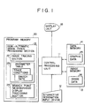
- the graphics processor comprises a central processing unit 11 for implementing a variety of processings, a program memory 20 for storing programs required for the processing to be implemented by the central processing unit 11, an image memory 13 for storing image data 26 to be the object for digitizing, a data memory 14 for storing graphic data 25 as the result of digitizing, an interactive designation inputting device 12 for inputting the interactive designation from the operator, and a display unit 16 for displaying the image data 26 and the graphic data 25.
- the program memory 20 stores the program for a semi-automatic image trace processing unit 21 which implements a variety of graphic operations
- the semi-automatic image processing section 21 comprises an image tracing section 22 for tracing the image in a semi-automatic fashion, a parameter table 23 for providing control data on the tracing condition for tracing the image points and control data on the correction processing due to the result of tracing, and a branch-point neighborhood display processing section 24 for enlarging a display of the area or portion in the neighborhood or vicinity of the branch point at the time of selecting the tracing path on an interactive basis.
- the parameter table 23 contains parameter data for the tracing conditions, such as a parameter data for determining the order of priority of the tracing path to be traced, parameter data for adjusting the result of tracing, and parameter data for adding the attribute to the result of tracing, and switch data for controlling the tracing path of the image at the branch points or the like in the semi-automatic trace processing as well.
- parameter data for the tracing conditions such as a parameter data for determining the order of priority of the tracing path to be traced, parameter data for adjusting the result of tracing, and parameter data for adding the attribute to the result of tracing, and switch data for controlling the tracing path of the image at the branch points or the like in the semi-automatic trace processing as well.
- the central processing unit 11 is to implement the trace processing of the image by reading the image data 25 on the basis of the semi-automatic image trace processing section 21 in the program memory 20.
- the image tracing section 22 implements the semi-automatic trace processing in accordance with the tracing conditions set in the control data in the parameter table 23.
- the trace processing is interrupted and the display of the area or portion in the neighborhood of the branch point is enlarged by the branch-point neighborhood display processing section 24 when the trace path should be selected on an interactive basis.
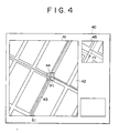
- the enlarged display of the neighborhood area of the branch point is made on the auxiliary view port disposed separately from the main view port on which the whole area of the trace path is to be displayed, as shown in Figs. 4 and 5.
- the operator can give the designation for tracing through the interactive designation inputting device 12 while reference is made to the enlarged display of the area in the neighborhood of the branch point/and the image tracing section 22 continues tracing the image, for example, by changing the direction of tracing upon the input designation.
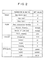
- Fig. 2 diagrammatically represents a specific example of the parameters and the switches as the control data to be set in the parameter table 23.
- the parameters for the tracing conditions to be operated by TRACE Command include the maximum width (Max Width) of the image points (dots) to be traced as a result of decision made to be a line, the size of a gap (Gap) to be traced as a result of the decision made to be a continuous line by neglecting missing dots of a line image and a distance (Step) to be checked by the trace Processing.
- control data for the correction processing based on the result of tracing to be operated by ADJUST Command for providing the adjust conditions there have been set the number of dots for the range of the tolerance in order to be accepted as a straight line (Straighten), the number of dots for the tolerance length of chamfer segment in order to be accepted as a Corner portion (Corner), the range of the tolerance angle of deviation in order to be accepted as a corner portion (Angle), and an accepted closing range in order to make a graphic form closed by connecting the end point by tracing (Closing).
- ATTRIBUTE Command includes a color (Color), the layer in which the graphic data as the result of tracing is allocated (Layer), and the kind of lines, such as a solid line, a broken line, one-dot chain lines or the like (Line).
- the parameters of those items are set in the parameter table 23 in advance and the trace processing is implemented in a semi-automatic fashion.
- Fig. 3 illustrates the flowchart for implementing the, trace processing of the image in a semi-automatic way.
- Fig. 4 illustrates an example of the display screen to be displayed during the semi-automatic image trace processing.
- the display screen 40 of the display unit 16 has the main view port 41 on which the image data 42 is displayed.
- the central processing unit 11 is so designed as to trace semi-automatically the image data 42 displayed on the main view port 41 on the basis of the program stored in the semi-automatic image trace processing section 21.
- step 101 the image points (dots) of the image to be the object for tracing are traced.
- the locus 43 of tracing is simultaneously displayed on the image data 42 on the main view port 41 displayed on the display screen 40.
- step 102 the result of tracing is converted into vector data and stored as the graphic data 25 in the data memory 14.
- the result of tracing is subjected to decision processing at steps 103, 104 and 105. In other words, at step 103, a decision is made to determine if the trace end condition has been detected.
- step 104 the program flow goes to step 104 at which a decision is further made to determine if the selection chance for the trace path (branch point or the like) has been detected.
- the program flow return to step 101 and the trace processing is repeated.
- step 104 When the result of decision at step 104 indicates that the selection chance for the trace path has been detected, on the other, hand, the program flow goes to step LOS; and a decision is made here to determine if the path control switch is set automatically by reading the status of the control switch for the trace path in correspondence with the kind of the selection chance for the trace path from the parameter table 23.
- step 105 indicates that the path control switch is set to be automatic
- the program flow goes to step 106 at which the trace path is automatically selected in accordance with the trace conditions corresponding to the parameters set in the parameter table 23, in other words, at which the direction of branching is selected, for example, followed by the return to step 101 from which the trace processing is repeated to continue the automatic trace processing.
- step 105 If the result of decision at step 105 indicates that the path control switch is not set to be automatic, on the other hand, this means that the trace processing is to be implemented on an interactive basis, so that the program flow proceeds to step 107 at which the trace path is controlled in an interactive mode.
- step 107 for example, as shown in Fig. 4, a constant range in the neighborhood of a branch point P1 containing the branch point P1 is enlarged and displayed on the auxiliary view port 45. This enlarged display is conducted by the branch-point neighborhood display processing section 24 Thereafter, the program flow goes to step 108 at which the designation is inputted by the operator, followed by proceeding to step 109 at which the trace path is selected in accordance with the designation by the operator and by the return of the program flow to step 101 for repeating the trace processing.
- step 110 the program flow goes to step 110 at which the trace result is adjusted in accordance with the parameters for the adjust conditions for the graphic data stored in the parameter table 23.
- This is the processing for adjusting the graphic data 25 by fetching it from the data memory 14.
- step 111 the attribute is added to the result of tracing in accordance with the parameters for providing the attribute stored in the parameter table 23, followed by storing the graphic data 25 in the data memory 14 again, thereby concluding the semi-automatic image trace processing.
- the trace path can automatically be selected when the trace path of the image can be defined uniformly by the switching operation so as to designate the control switch by the data in the parameter table in association with the switching function for controlling the trace path in tracing the image in a semi-automatic fashion.
- the trace path of the image cannot be defined uniformly, the trace path can be designated on an interactive basis when the designation of the trace path is required.
- the trace processing can be continued while the trace path is selected by the interactive designation whenever the trace path reaches the branch points one after another.
- the image in the neighborhood of the branch point is displayed in an enlarged manner on the auxiliary view port disposed separately from the main view port on which the whole area of the trace range is displayed, so that the operator can accurately select the direction of branching while looking at the display on the auxiliary view port, thereby saving laborious work for confirmation of the detail of the trace path or correction of an error in the trace path, which has been otherwise required in conventional techniques.
- Fig. 5 is a diagrammatic representation showing another example of the display screen to be displayed in the semi-automatic trace processing.
- the example of the display screen as shown in Fig. 5 is similar to the example of the display screen as shown in Fig. 4, except for the manner in which the auxiliary view port 46 is opened as a sub-window in the main view port 41.
- the auxiliary view port 46 is opened as the sub-window in a position in the vicinity of the branch point P1 the neighborhood of which is to be displayed in an enlarged fashion on the auxiliary view port 46.
- This type of the auxiliary view port 46 allows better correspondence of the branch point P1 displayed on the main view port 41 with the branch point P1 displayed in an enlarged way.
- this way of display can provide the sense of direction for the enlarged image display on the auxiliary view port 46 in the same manner 25 the sense of direction for the image display on the main view port 41 on which the whole area of the trace path is displayed, thereby allowing the operator to avoid an error in giving the designation of the direction for the trace path.
- the semi-automatic image tracing method and device allow' the graphics processor to designate the switch for controlling the trace path of the image and shift the switch in implementing the processing of tracing the image in a semi-automatic way, thereby defining the trace path in a uniform manner and, alternatively, to designate the digitizing path on an interactive basis.
- the area or portion in the neighborhood of every branch point at a junction where the paths are connected to each other can be displayed in an enlarged fashion, so that the operator can accurately select the direction in which the trace path is branched.
- This type of semi-automatic image trace processing can save laborious work required for confirmation of details of the trace path and correction of errors in the trace path after tracing.
Landscapes
- Physics & Mathematics (AREA)
- General Physics & Mathematics (AREA)
- Engineering & Computer Science (AREA)
- Theoretical Computer Science (AREA)
- Processing Or Creating Images (AREA)
Applications Claiming Priority (2)
| Application Number | Priority Date | Filing Date | Title |
|---|---|---|---|
| JP291750/89 | 1989-11-08 | ||
| JP1291750A JP2873840B2 (ja) | 1989-11-08 | 1989-11-08 | 図形処理装置 |
Publications (3)
| Publication Number | Publication Date |
|---|---|
| EP0431339A2 true EP0431339A2 (fr) | 1991-06-12 |
| EP0431339A3 EP0431339A3 (en) | 1992-04-01 |
| EP0431339B1 EP0431339B1 (fr) | 1999-02-03 |
Family
ID=17772930
Family Applications (1)
| Application Number | Title | Priority Date | Filing Date |
|---|---|---|---|
| EP90121377A Expired - Lifetime EP0431339B1 (fr) | 1989-11-08 | 1990-11-08 | Méthode et appareil pour tracer une image de façon semi-automatique |
Country Status (4)
| Country | Link |
|---|---|
| US (1) | US5253338A (fr) |
| EP (1) | EP0431339B1 (fr) |
| JP (1) | JP2873840B2 (fr) |
| DE (1) | DE69032934T2 (fr) |
Families Citing this family (18)
| Publication number | Priority date | Publication date | Assignee | Title |
|---|---|---|---|---|
| JPH0512442A (ja) * | 1991-07-02 | 1993-01-22 | Hitachi Software Eng Co Ltd | 線画像追跡方法 |
| US5384909A (en) * | 1991-12-19 | 1995-01-24 | International Business Machines Corporation | Precision automatic scrolling for an image display system |
| US5680629A (en) * | 1992-12-07 | 1997-10-21 | Microsoft Corporation | Method and system for previewing computer output |
| US5384904A (en) * | 1992-12-08 | 1995-01-24 | Intel Corporation | Image scaling using real scale factors |
| JPH06342357A (ja) * | 1993-06-01 | 1994-12-13 | Mitsubishi Electric Corp | ユーザインタフェース方式 |
| US5459832A (en) * | 1993-08-18 | 1995-10-17 | Ast Research, Inc. | Method and apparatus for editing groups of graphic images |
| US5652901A (en) * | 1994-12-23 | 1997-07-29 | Microsoft Corporation | Method and system for previewing computer output |
| US5835640A (en) * | 1995-05-03 | 1998-11-10 | Seiko Epson Corporation | Method and apparatus for identifying and fixing horizontal and vertical lines in digitized images |
| US5611124A (en) * | 1995-05-10 | 1997-03-18 | Batesville Casket Company, Inc. | Casket having memorabilia compartment |
| US6445399B1 (en) * | 1998-01-20 | 2002-09-03 | Rafael - Armament Development Authority Ltd. | System and method of visual orientation |
| JP4340358B2 (ja) * | 1999-08-02 | 2009-10-07 | 富士フイルム株式会社 | 画像撮影装置 |
| US6897880B2 (en) | 2001-02-22 | 2005-05-24 | Sony Corporation | User interface for generating parameter values in media presentations based on selected presentation instances |
| KR100480770B1 (ko) * | 2001-07-12 | 2005-04-06 | 삼성전자주식회사 | 3차원 공간상의 정보 포인팅 방법 |
| US20030101237A1 (en) * | 2001-11-29 | 2003-05-29 | Shinichi Ban | Image forming program and image forming apparatus |
| FR2833132B1 (fr) * | 2001-11-30 | 2004-02-13 | Eastman Kodak Co | Procede pour selectionner et enregistrer un sujet d'interet dans une image numerique fixe |
| FR2833131B1 (fr) * | 2001-11-30 | 2004-02-13 | Eastman Kodak Co | Procede et systeme pour obtimiser l'affichage d'un sujet d'interet dans une image numerique |
| US7639237B2 (en) * | 2006-03-03 | 2009-12-29 | Perkins Michael T | Roll-out touch screen support system (ROTS3) |
| JP5760324B2 (ja) * | 2010-03-19 | 2015-08-05 | ソニー株式会社 | 画像処理装置、画像処理方法、画像処理プログラム並びにこの画像処理プログラムが記録された記録媒体 |
Citations (2)
| Publication number | Priority date | Publication date | Assignee | Title |
|---|---|---|---|---|
| US4561061A (en) * | 1981-04-06 | 1985-12-24 | Dainippon Screen Mfg. Co., Ltd. | Method of tracing/recording image lines and apparatus therefor |
| EP0246010A1 (fr) * | 1986-05-12 | 1987-11-19 | Crosfield Electronics Limited | Afficheur d'image |
Family Cites Families (3)
| Publication number | Priority date | Publication date | Assignee | Title |
|---|---|---|---|---|
| US4202037A (en) * | 1977-04-22 | 1980-05-06 | Der Loos Hendrik Van | Computer microscope apparatus and method for superimposing an electronically-produced image from the computer memory upon the image in the microscope's field of view |
| US4514818A (en) * | 1980-12-04 | 1985-04-30 | Quantel Limited | Video image creation system which simulates drafting tool |
| EP0112414B1 (fr) * | 1982-12-22 | 1987-09-09 | International Business Machines Corporation | Transformations d'image sur un affichage interactif à balayage à trame ou matriciel |
-
1989
- 1989-11-08 JP JP1291750A patent/JP2873840B2/ja not_active Expired - Fee Related
-
1990
- 1990-11-07 US US07/610,153 patent/US5253338A/en not_active Expired - Lifetime
- 1990-11-08 EP EP90121377A patent/EP0431339B1/fr not_active Expired - Lifetime
- 1990-11-08 DE DE69032934T patent/DE69032934T2/de not_active Expired - Lifetime
Patent Citations (2)
| Publication number | Priority date | Publication date | Assignee | Title |
|---|---|---|---|---|
| US4561061A (en) * | 1981-04-06 | 1985-12-24 | Dainippon Screen Mfg. Co., Ltd. | Method of tracing/recording image lines and apparatus therefor |
| EP0246010A1 (fr) * | 1986-05-12 | 1987-11-19 | Crosfield Electronics Limited | Afficheur d'image |
Also Published As
| Publication number | Publication date |
|---|---|
| EP0431339B1 (fr) | 1999-02-03 |
| EP0431339A3 (en) | 1992-04-01 |
| US5253338A (en) | 1993-10-12 |
| DE69032934D1 (de) | 1999-03-18 |
| JP2873840B2 (ja) | 1999-03-24 |
| JPH03152671A (ja) | 1991-06-28 |
| DE69032934T2 (de) | 1999-06-10 |
Similar Documents
| Publication | Publication Date | Title |
|---|---|---|
| EP0431339B1 (fr) | Méthode et appareil pour tracer une image de façon semi-automatique | |
| EP0249399B1 (fr) | Méthode et appareil de commande de fenêtres multiples pour un poste de travail avec fonction de fenêtres multiples | |
| KR900006042B1 (ko) | 복합문서 처리 장치용 표시 제어장치 | |
| US5262760A (en) | Modifying a graphics display image | |
| US5179655A (en) | Multiwindow control method and apparatus for work station having multiwindow function | |
| JPH06274586A (ja) | 表示方式 | |
| JPH05265689A (ja) | 情報処理装置 | |
| EP0427251B1 (fr) | Méthode et appareil pour traitement graphique | |
| US5208904A (en) | Data processing apparatus and method for preparing data representative of supplemental figure attached to basic figure reproduced on output medium | |
| US5646861A (en) | Method and apparatus for inputting embroidery lines | |
| US6864885B2 (en) | Graphic form correction method and apparatus for CAD system | |
| US5302967A (en) | Figure processing apparatus and method aided by display with ruled lines | |
| JP2729699B2 (ja) | 追跡始点入力方法および装置 | |
| JP3239292B2 (ja) | 図形編集処理システムの図形特定制御方法 | |
| JPH06215074A (ja) | 図形処理装置 | |
| JPH10154040A (ja) | 画像処理装置 | |
| JP2721344B2 (ja) | 画像処理方法 | |
| JP3299044B2 (ja) | 図形処理方法及び装置 | |
| JP3470974B2 (ja) | 図形作成方法および装置 | |
| JPH07105397A (ja) | Cadシステム用図形指示受取装置 | |
| JPH03107156A (ja) | 印刷製版用レイアウト装置 | |
| EP0406445A1 (fr) | Procede d'etablissement et de representation de parametres graphiques | |
| JPH0896159A (ja) | 図形編集装置 | |
| JPH03147080A (ja) | 図形情報処理装置 | |
| JPH0561608A (ja) | カーソル制御方法及び装置、並びに文書処理装置 |
Legal Events
| Date | Code | Title | Description |
|---|---|---|---|
| PUAI | Public reference made under article 153(3) epc to a published international application that has entered the european phase |
Free format text: ORIGINAL CODE: 0009012 |
|
| AK | Designated contracting states |
Kind code of ref document: A2 Designated state(s): DE |
|
| PUAL | Search report despatched |
Free format text: ORIGINAL CODE: 0009013 |
|
| AK | Designated contracting states |
Kind code of ref document: A3 Designated state(s): DE |
|
| 17P | Request for examination filed |
Effective date: 19920928 |
|
| 17Q | First examination report despatched |
Effective date: 19951218 |
|
| GRAG | Despatch of communication of intention to grant |
Free format text: ORIGINAL CODE: EPIDOS AGRA |
|
| GRAG | Despatch of communication of intention to grant |
Free format text: ORIGINAL CODE: EPIDOS AGRA |
|
| GRAH | Despatch of communication of intention to grant a patent |
Free format text: ORIGINAL CODE: EPIDOS IGRA |
|
| GRAH | Despatch of communication of intention to grant a patent |
Free format text: ORIGINAL CODE: EPIDOS IGRA |
|
| GRAA | (expected) grant |
Free format text: ORIGINAL CODE: 0009210 |
|
| AK | Designated contracting states |
Kind code of ref document: B1 Designated state(s): DE |
|
| REF | Corresponds to: |
Ref document number: 69032934 Country of ref document: DE Date of ref document: 19990318 |
|
| PLBE | No opposition filed within time limit |
Free format text: ORIGINAL CODE: 0009261 |
|
| STAA | Information on the status of an ep patent application or granted ep patent |
Free format text: STATUS: NO OPPOSITION FILED WITHIN TIME LIMIT |
|
| 26N | No opposition filed | ||
| PGFP | Annual fee paid to national office [announced via postgrant information from national office to epo] |
Ref country code: DE Payment date: 20091130 Year of fee payment: 20 |
|
| PG25 | Lapsed in a contracting state [announced via postgrant information from national office to epo] |
Ref country code: DE Free format text: LAPSE BECAUSE OF EXPIRATION OF PROTECTION Effective date: 20101108 |