EP0430652A2 - Gedämpfte Lagerung für Oberflächenwellenanordnung - Google Patents
Gedämpfte Lagerung für Oberflächenwellenanordnung Download PDFInfo
- Publication number
- EP0430652A2 EP0430652A2 EP90312895A EP90312895A EP0430652A2 EP 0430652 A2 EP0430652 A2 EP 0430652A2 EP 90312895 A EP90312895 A EP 90312895A EP 90312895 A EP90312895 A EP 90312895A EP 0430652 A2 EP0430652 A2 EP 0430652A2
- Authority
- EP
- European Patent Office
- Prior art keywords
- sensitive device
- pressure sensitive
- cradle
- substrate
- pressure
- Prior art date
- Legal status (The legal status is an assumption and is not a legal conclusion. Google has not performed a legal analysis and makes no representation as to the accuracy of the status listed.)
- Withdrawn
Links
Images
Classifications
-
- H—ELECTRICITY
- H03—ELECTRONIC CIRCUITRY
- H03H—IMPEDANCE NETWORKS, e.g. RESONANT CIRCUITS; RESONATORS
- H03H9/00—Networks comprising electromechanical or electro-acoustic elements; Electromechanical resonators
- H03H9/02—Details
- H03H9/05—Holders or supports
- H03H9/058—Holders or supports for surface acoustic wave devices
-
- H—ELECTRICITY
- H03—ELECTRONIC CIRCUITRY
- H03H—IMPEDANCE NETWORKS, e.g. RESONANT CIRCUITS; RESONATORS
- H03H9/00—Networks comprising electromechanical or electro-acoustic elements; Electromechanical resonators
- H03H9/02—Details
- H03H9/05—Holders or supports
- H03H9/09—Elastic or damping supports
Definitions
- the present invention relates to mounting apparatus for pressure sensitive components, and more particularly to a damped cradle suitable for mounting a piezoelectric surface acoustic wave (SAW) device on a substrate to provide increased vibration control with minimum induced stresses in the SAW device.
- SAW piezoelectric surface acoustic wave
- SAW devices are pressure sensitive crystals that are used widely in various applications, such as in oscillators and filters.
- the acoustic/mechanical properties of these devices are critical to their operation, and their physical attachment to a stable support may impact these acoustic/mechanical properties, and thus their operation.
- Stress related frequency drifts may occur in the SAW devices as a result of their physical attachment to the stable support from two sources. One is caused when large temperature excursions occur and materials having different thermal coefficients of expansion are in contact with the crystal. Another is caused by the physical contact of the support mechanism that produces pressure on the crystal, even when contact is in non-active areas of the crystal.
- Other mounting means such as adhesives, may outgas under high vacuum conditions in a hermetically sealed package, contaminating the SAW device surface.
- a cradle construction that may be used to mount a SAW device to a stable substrate with minimal induced stress while providing significant damping of motion in a vibration or shock environment.
- the present invention provides a damped cradle for a pressure sensitive device that is of unitary construction and provides minimal pressure, spring contact with non-active areas of the pressure sensitive device to provide friction damping of motion in a vibration or shock environment.
- the cradle has a base that is attached to the stable substrate by suitable means, integral side arms that have spring tips that lightly contact non-active side surfaces of the pressure sensitive device, and integral top spring arms with compliant tips that lightly contact non-active areas of the top surface of the pressure sensitive device.
- the surface contact of the device with the substrate is such as to provide a smooth transition from static to dynamic friction, with the light pressure of the top spring arms providing sufficient downward pressure to induce frictional movement of the device across the substrate surface to damp motion. Upward motion of the device is damped due to frictional movement between the device sides and the spring tips.
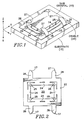
- Fig. 1 is a perspective view of a pressure sensitive device mounted on a substrate using a damped cradle according to the present invention.
- Fig. 2 is a top plan view of the damped cradle of Fig. 1 prior to shaping according to the present invention.
- a pressure sensitive device such as a SAW crystal 10 is mounted on a substrate 15.
- the crystal 10 is held on the substrate 15 by a cradle 20 that is fixedly attached to the substrate by any suitable means, such as welding, epoxy bonding, soldering or the like.
- the cradle 20 is a single, integral unit, as shown in Fig. 2, having a base portion 22 that is attached to the substrate. Extending upward from an internal edge of the base portion 22 are four restraining arms 24, one for each side of the crystal 10. Each restraining arm 24 has a pair of spring tips 25 that actually contact the sides of the crystal 10 with light pressure. Extending upward from an external edge of the base portion are four spring arms 26 that curve over the top edge of the crystal 10. At the end of each spring arm 26 is a compliant tip 27 that contacts the top surface of the crystal 10 at non-active areas with a light pressure.
- the cradle 20 may be formed by any suitable technique, such as etching, to produce the configuration shown in Fig. 2.
- the material of the cradle is such as to provide a certain stiffness together with springiness, and to have a desired coefficient of friction to assist in frictional damping, such as beryllium-copper, stainless steel or the like.
- the side arms 24 are bent upward with the spring tips 25 bent inward.
- the spring arms 26 also are bent upward and back over the base portion 22 with the tips bent downward.
- the base portion 22 is attached to the substrate 15 and the crystal 10 is placed within the cradle 20.
- the spring tips 25 and compliant tips 27 are adjusted to contact the crystal 10 with a total pressure force that approaches zero to minimize the propagation of induced stresses throughout the crystal. Further the tips 25, 27 may be plated or otherwise treated to provide a desired friction damping to the crystal 10.
- a polished quartz bottom surface for the crystal 10 contacting a smooth, soft gold surface plated on the substrate 15 is known to have minimum damping chatter.
- the compliant tips 27 in the Z axis provide enough force to overcome the maximum vibration acceleration forces the crystal 10 mass encompasses for a given application.
- the present invention provides a damped cradle for a SAW device with an improved vibration/shock isolation control on the order of one to two magnitudes better than prior art for hermetic packages without the use of organic materials.
- a one-piece cradle construction applies a balanced spring force to the SAW device at non-active areas and frictional damping reduces vibration effects on the SAW device.
Landscapes
- Physics & Mathematics (AREA)
- Acoustics & Sound (AREA)
- Vibration Prevention Devices (AREA)
- Surface Acoustic Wave Elements And Circuit Networks Thereof (AREA)
- Piezo-Electric Or Mechanical Vibrators, Or Delay Or Filter Circuits (AREA)
Applications Claiming Priority (2)
| Application Number | Priority Date | Filing Date | Title |
|---|---|---|---|
| US442277 | 1989-11-28 | ||
| US07/442,277 US5109177A (en) | 1989-11-28 | 1989-11-28 | Damped cradle for saw device |
Publications (2)
| Publication Number | Publication Date |
|---|---|
| EP0430652A2 true EP0430652A2 (de) | 1991-06-05 |
| EP0430652A3 EP0430652A3 (en) | 1991-07-24 |
Family
ID=23756204
Family Applications (1)
| Application Number | Title | Priority Date | Filing Date |
|---|---|---|---|
| EP19900312895 Withdrawn EP0430652A3 (en) | 1989-11-28 | 1990-11-27 | Damped cradle for saw device |
Country Status (4)
| Country | Link |
|---|---|
| US (1) | US5109177A (de) |
| EP (1) | EP0430652A3 (de) |
| JP (1) | JPH0760125B2 (de) |
| CA (1) | CA2027367A1 (de) |
Cited By (1)
| Publication number | Priority date | Publication date | Assignee | Title |
|---|---|---|---|---|
| EP0520270A1 (de) * | 1991-06-28 | 1992-12-30 | AME Space A/S | Mittel zum Montieren eines länglichen Körpers |
Families Citing this family (5)
| Publication number | Priority date | Publication date | Assignee | Title |
|---|---|---|---|---|
| JP3221253B2 (ja) * | 1994-09-13 | 2001-10-22 | 株式会社村田製作所 | 複合電子部品の製造方法 |
| US6113056A (en) * | 1998-08-04 | 2000-09-05 | Micrion Corporation | Workpiece vibration damper |
| TWM264748U (en) * | 2004-06-08 | 2005-05-11 | Midas Wei Trading Co Ltd | Improved piezoelectric transformer carrier |
| US20080127750A1 (en) * | 2006-12-05 | 2008-06-05 | Honeywell International Inc. | Reducing strain level in torque sensing system |
| US8638318B2 (en) * | 2010-05-28 | 2014-01-28 | Elo Touch Solutions, Inc. | Multi-layer coversheet for saw touch panel |
Family Cites Families (18)
| Publication number | Priority date | Publication date | Assignee | Title |
|---|---|---|---|---|
| US1619854A (en) * | 1926-02-26 | 1927-03-08 | Wired Radio Inc | Piezo-electric-crystal apparatus |
| US1766036A (en) * | 1927-04-14 | 1930-06-24 | Fed Telegraph Co | Piezo-electric crystal apparatus |
| US1882885A (en) * | 1928-04-18 | 1932-10-18 | Bell Telephone Labor Inc | Holder for crystal resonators |
| US1933601A (en) * | 1929-06-05 | 1933-11-07 | Rca Corp | Piezo electric crystal holder |
| US2029359A (en) * | 1934-04-20 | 1936-02-04 | Goodrich Co B F | Apparatus for shirring rubber articles |
| US2044145A (en) * | 1934-09-18 | 1936-06-16 | Westinghouse Electric & Mfg Co | Crystal holder |
| US2285143A (en) * | 1940-01-02 | 1942-06-02 | Rca Corp | Mounting piezoelectric elements |
| US2412438A (en) * | 1943-10-12 | 1946-12-10 | Premier Crystal Lab Inc | Piezo-crystal holder |
| US2409607A (en) * | 1943-10-15 | 1946-10-22 | Premier Crystal Lab Inc | Multiple crystal holder |
| US2482451A (en) * | 1945-06-07 | 1949-09-20 | Reeves Hoffman Corp | Piezoelectric crystal holder |
| US3885173A (en) * | 1973-10-09 | 1975-05-20 | Magnavox Co | Apparatus and method for coupling an acoustical surface wave device to an electronic circuit |
| JPS53121675A (en) * | 1977-03-31 | 1978-10-24 | Hitachi Ltd | Method and apparatus of measuring surface stress |
| US4267479A (en) * | 1977-09-16 | 1981-05-12 | Citizen Watch Co., Ltd. | Mounting clips for thickness shear piezoelectric oscillator |
| US4845397A (en) * | 1984-12-19 | 1989-07-04 | Tektronix, Inc. | Constraining mount system for surface acoustic wave devices |
| CA1271556A (en) * | 1984-12-19 | 1990-07-10 | Geoffrey C. Herrick | Constraining mount system for surface acoustic wave devices |
| US4618797A (en) * | 1984-12-24 | 1986-10-21 | Cline David J | Environmentally sealed piezoelectric sensing assembly for electrical switch |
| JPS6380514U (de) * | 1986-11-14 | 1988-05-27 | ||
| FR2612021A1 (fr) * | 1987-03-06 | 1988-09-09 | Cepe | Ressorts de suspension d'une lame vivrante piezoelectrique |
-
1989
- 1989-11-28 US US07/442,277 patent/US5109177A/en not_active Expired - Lifetime
-
1990
- 1990-10-11 CA CA002027367A patent/CA2027367A1/en not_active Abandoned
- 1990-11-27 EP EP19900312895 patent/EP0430652A3/en not_active Withdrawn
- 1990-11-28 JP JP2328772A patent/JPH0760125B2/ja not_active Expired - Lifetime
Cited By (2)
| Publication number | Priority date | Publication date | Assignee | Title |
|---|---|---|---|---|
| EP0520270A1 (de) * | 1991-06-28 | 1992-12-30 | AME Space A/S | Mittel zum Montieren eines länglichen Körpers |
| US5323081A (en) * | 1991-06-28 | 1994-06-21 | Ame Space As | Surface acoustic wave device clamped within housing |
Also Published As
| Publication number | Publication date |
|---|---|
| US5109177A (en) | 1992-04-28 |
| EP0430652A3 (en) | 1991-07-24 |
| CA2027367A1 (en) | 1991-05-29 |
| JPH03174812A (ja) | 1991-07-30 |
| JPH0760125B2 (ja) | 1995-06-28 |
Similar Documents
| Publication | Publication Date | Title |
|---|---|---|
| US6484578B2 (en) | Vibrating beam accelerometer | |
| US5755978A (en) | Accelerometer and method of manufacture | |
| US4398117A (en) | Bellows support for surface acoustic wave device | |
| US4845397A (en) | Constraining mount system for surface acoustic wave devices | |
| US5109177A (en) | Damped cradle for saw device | |
| JPS61502636A (ja) | 振動ビ−ム加速度計 | |
| JP2531266B2 (ja) | 振動子の支持構造 | |
| US6128957A (en) | Active cover accelerometer | |
| EP0791832B1 (de) | Vibrator | |
| JPS58500218A (ja) | センサーハウジング用振動隔離装置 | |
| JP2002195834A (ja) | 物理量検出装置 | |
| US5030876A (en) | Mounting structure for crystal resonator | |
| JPS63260310A (ja) | 縦水晶振動子 | |
| JPH0534849B2 (de) | ||
| KR100198305B1 (ko) | 진동 자이로스코프 | |
| JPH116736A (ja) | 角速度センサ | |
| JP3352856B2 (ja) | 振動子の保護装置 | |
| US5450762A (en) | Reactionless single beam vibrating force sensor | |
| JPH0534848B2 (de) | ||
| CA1271556A (en) | Constraining mount system for surface acoustic wave devices | |
| Parker et al. | SAW oscillators with low vibration sensitivity | |
| JPS5950128B2 (ja) | 縦振動子の支持構造 | |
| JP2668697B2 (ja) | 輪郭すべり水晶振動子 | |
| JPH01212013A (ja) | 縦水晶振動子 | |
| JP2684999B2 (ja) | 電子機器の防振器 |
Legal Events
| Date | Code | Title | Description |
|---|---|---|---|
| PUAI | Public reference made under article 153(3) epc to a published international application that has entered the european phase |
Free format text: ORIGINAL CODE: 0009012 |
|
| AK | Designated contracting states |
Kind code of ref document: A2 Designated state(s): DE FR GB NL |
|
| PUAL | Search report despatched |
Free format text: ORIGINAL CODE: 0009013 |
|
| AK | Designated contracting states |
Kind code of ref document: A3 Designated state(s): DE FR GB NL |
|
| 17P | Request for examination filed |
Effective date: 19910723 |
|
| RAP1 | Party data changed (applicant data changed or rights of an application transferred) |
Owner name: TEKTRONIX, INC. |
|
| 17Q | First examination report despatched |
Effective date: 19931013 |
|
| GRAG | Despatch of communication of intention to grant |
Free format text: ORIGINAL CODE: EPIDOS AGRA |
|
| GRAH | Despatch of communication of intention to grant a patent |
Free format text: ORIGINAL CODE: EPIDOS IGRA |
|
| STAA | Information on the status of an ep patent application or granted ep patent |
Free format text: STATUS: THE APPLICATION IS DEEMED TO BE WITHDRAWN |
|
| 18D | Application deemed to be withdrawn |
Effective date: 19961203 |