EP0430252B1 - Portable apparatus having detachable storage unit - Google Patents
Portable apparatus having detachable storage unit Download PDFInfo
- Publication number
- EP0430252B1 EP0430252B1 EP90122872A EP90122872A EP0430252B1 EP 0430252 B1 EP0430252 B1 EP 0430252B1 EP 90122872 A EP90122872 A EP 90122872A EP 90122872 A EP90122872 A EP 90122872A EP 0430252 B1 EP0430252 B1 EP 0430252B1
- Authority
- EP
- European Patent Office
- Prior art keywords
- lock
- slider
- connector
- base unit
- storage means
- Prior art date
- Legal status (The legal status is an assumption and is not a legal conclusion. Google has not performed a legal analysis and makes no representation as to the accuracy of the status listed.)
- Expired - Lifetime
Links
Images


Classifications
-
- G—PHYSICS
- G06—COMPUTING; CALCULATING OR COUNTING
- G06F—ELECTRIC DIGITAL DATA PROCESSING
- G06F1/00—Details not covered by groups G06F3/00 - G06F13/00 and G06F21/00
-
- G—PHYSICS
- G06—COMPUTING; CALCULATING OR COUNTING
- G06F—ELECTRIC DIGITAL DATA PROCESSING
- G06F1/00—Details not covered by groups G06F3/00 - G06F13/00 and G06F21/00
- G06F1/16—Constructional details or arrangements
- G06F1/1613—Constructional details or arrangements for portable computers
- G06F1/1615—Constructional details or arrangements for portable computers with several enclosures having relative motions, each enclosure supporting at least one I/O or computing function
- G06F1/1616—Constructional details or arrangements for portable computers with several enclosures having relative motions, each enclosure supporting at least one I/O or computing function with folding flat displays, e.g. laptop computers or notebooks having a clamshell configuration, with body parts pivoting to an open position around an axis parallel to the plane they define in closed position
-
- G—PHYSICS
- G06—COMPUTING; CALCULATING OR COUNTING
- G06F—ELECTRIC DIGITAL DATA PROCESSING
- G06F1/00—Details not covered by groups G06F3/00 - G06F13/00 and G06F21/00
- G06F1/16—Constructional details or arrangements
- G06F1/1613—Constructional details or arrangements for portable computers
- G06F1/1633—Constructional details or arrangements of portable computers not specific to the type of enclosures covered by groups G06F1/1615 - G06F1/1626
- G06F1/1656—Details related to functional adaptations of the enclosure, e.g. to provide protection against EMI, shock, water, or to host detachable peripherals like a mouse or removable expansions units like PCMCIA cards, or to provide access to internal components for maintenance or to removable storage supports like CDs or DVDs, or to mechanically mount accessories
-
- Y—GENERAL TAGGING OF NEW TECHNOLOGICAL DEVELOPMENTS; GENERAL TAGGING OF CROSS-SECTIONAL TECHNOLOGIES SPANNING OVER SEVERAL SECTIONS OF THE IPC; TECHNICAL SUBJECTS COVERED BY FORMER USPC CROSS-REFERENCE ART COLLECTIONS [XRACs] AND DIGESTS
- Y10—TECHNICAL SUBJECTS COVERED BY FORMER USPC
- Y10T—TECHNICAL SUBJECTS COVERED BY FORMER US CLASSIFICATION
- Y10T292/00—Closure fasteners
- Y10T292/08—Bolts
- Y10T292/096—Sliding
- Y10T292/1014—Operating means
- Y10T292/1022—Rigid
- Y10T292/1031—Swinging catch
Definitions
- the present invention relates to a portable apparatus such as a lap-top type or portable type computer. More particularly, this invention relates to a structure for detachably mounting a storage unit such as a hard-disk drive device (HDD) or a floppy-disk drive device (FDD) in a base unit of a computer.
- a storage unit such as a hard-disk drive device (HDD) or a floppy-disk drive device (FDD) in a base unit of a computer.
- HDD hard-disk drive device
- FDD floppy-disk drive device
- an HDD or FDD is mounted in a base unit, as disclosed in U.S. Patent No. 4,903,222.
- an auxiliary HDD formed into a unit as one module is detachably mounted in a base unit to process a large amount of data.
- This HDD includes a box-like flat case having a first connector.
- a driving unit for rotating a hard disk, and a head for writing and reading data in and from the hard disk are housed.
- the head and the driving unit are electrically connected to the first connector.
- the base unit includes a receiving portion for mounting the HDD.
- the receiving portion is open to the rear surface of a rear portion of the base unit, and a second connector is arranged in this opening.
- the second connector is electrically connected to electronic equipments mounted in the base unit.
- the base unit includes a lock unit for holding the HDD in the opening.
- the HDD When the HDD is locked by this lock unit, the HDD cannot move inside the opening to prevent disconnection of the first and second connectors from each other.
- the lock unit is designed such that lock and lock release operations of the HDD can be simply performed by only sliding a knob. For this reason, if an operator erroneously slides the knob in the lock release direction while data write or read operation is performed, the lock of the HDD is released, and the connectors for connecting the HDD to the base unit may be disconnected from each other.
- the prior art hard disk drive module and receptacle as disclosed in reference WO 88/06780 discloses a system where the hard disk drive module is manually inserted into the receptacle until the rear surface of the module is engaged with posts of a slide Due to this engagement, the slide is pushed back and the slide panel coupled to the slide by a hinge pin is rotated upward due to the guiding action of a ramp of the receptacle casing such that fingers of the panel are engaged with recesses in the module.
- the reciprocating motion of the slide in the receptacle is transmitted into rotating movement of a cam by means of a crank and a connecting link .
- the cam in a specific insertion position activates a motor through a micro switch for further rotating the cam to insert the module into an operating position.
- a connector of the module is connected to a connector of the receptacle and the module is electrically connected to the system.
- the first and second connectors are electrically connected to each other.
- the switch means is turned on to allow supply of a current to the storage means.
- the storage means housed in the receiving portion of the base unit is fixed to the receiving portion by the fixing means.
- This fixing means not only fixes the storage means but also engages it with the lock means, thus holding the lock means in a state wherein the storage means is locked to the receiving portion.
- the lock means therefore, is kept locked unless the fixed state of the storage means by means of the fixing means is released, and the storage means cannot be detached from the receiving portion.
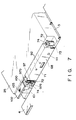
- Fig. 1 shows a lap-top type portable computer 1.
- the portable computer 1 includes a base unit 2 and a flat panel type display unit 3.
- the base unit 2 is formed into a thin box having a rectangular shape.
- a floppy-disk drive device (FDD) is housed in the base unit 2.
- FDD floppy-disk drive device
- the base unit 2 includes a bottom case 5 in which a printed circuit board 4 is housed, and a top cover 6 for covering the bottom case 5.
- the top cover 6 consists of front portion 6a and rear portion 6b.
- a keyboard 7 is attached to the front portion 6a of the top cover 6.
- the rear portion 6b of the top cover 6 protrudes upward from the keyboard 7.
- a pair of mounting recesses 8 are formed at the front end of the rear portion 6b of the top cover 6.
- the display unit 3 includes a rectangular housing 10 and a flat display 11 housed in this housing 10.
- the display 11 is externally exposed through an opening 12 in the front surface of the housing 10.
- the housing 10 of the display unit 3 has a pair of leg portions 13 to be respectively inserted in the mounting recesses 8 of the top cover 6.
- the leg portions 13 are pivotally coupled to the mounting recesses 8 of the top cover 6 by means of hinges (not shown), respectively. With this coupling, the display unit 3 is rotated between a closed position where the keyboard 7 is covered and an upright position where the keyboard 7 and the display 11 are exposed during an operation of the keyboard 7, as indicated by an arrow X in Fig. 1.
- the bottom case 5 of the base unit 2 has a flat bottom plate 15.
- a hard-disk drive device (HDD) 16 having a relatively large storage capacity is detachably mounted in a rear portion of the bottom plate 15 so that a system storage capacity is improved.
- a structure for mounting this HDD 16 will be described below.
- the HDD 16 has a case 17 having a flat, rectangular box-like shape.
- the case 17 includes front portion 17a and rear portion 17b.
- a driving unit for driving the hard disk and a head unit are housed in the case 17.
- the head unit is used to write and read data in and from the hard disk.
- a cover plate 18 of the case 17 has a flat, rectangular plate-like shape.
- the four peripheral edge portions of the cover plate 18 extend outward from the side surfaces of the case 17.
- a peripheral edge portion 18c corresponding to the rear portion 17b of the case 17 has a notch 19 formed therein.
- a columnar engaging projection 20 is formed on the rear surface of the rear portion 17b of the case 17. This engaging projection 20 extends backward from the case 17.
- Guide projections 21 respectively extend from the right and left side surfaces of the front portion 17a of the case 17.
- Hook pieces 22 respectively extend from the front ends of the right and left side surfaces of the case 17. The hook pieces 22 extend forward from the front surface of the front portion 17a of the case 17 and from the cover plate 18.
- a connector mounting port 23 is formed in the front surface of the front portion 17a of the case 17 so as to extend in a lateral direction.
- a first connector 24 is mounted in the connector mounting port 23. The first connector 24 is electrically connected to the driving unit and the head unit in the case 17.
- a receiving portion 25 for detachably mounting the HDD 16 is formed in the bottom plate 15 of the bottom case 5.
- the receiving portion 25 is set back from the bottom case 5.
- the recess 25 has a size to allow the case 17 to be fitted therein.
- the recess 25 is located below the rear portion 6b of the top cover 6 and constitutes an insertion opening 26 in the bottom plate 15 of the bottom case 5 so as to allow the HDD 16 to be inserted therein.
- a fitting portion 27 is formed in the edge defining the insertion opening 26.
- the edge of the cover plate 18 of the case 17 is to be fitted in the fitting portion 27. When the edge of the cover plate 18 is fitted in the fitting portion 27, the cover plate 18 of the case 17 becomes continuous with the bottom plate 15 of the bottom case 5 so that the cover plate 18 of the case 17 serves as a portion of the bottom plate 15 of the bottom case 5.
- the recess 25 of the bottom case 5 includes a front surface 25a, a rear surface 25b, a pair of right and left side surfaces 25c and 25d, and a bottom surface 25e.
- Guide grooves 28 in which the guide projections 21 of the case 17 are inserted are formed in the right and left side surfaces 25c and 25d of the recess 25.
- Each guide groove 28 extends upward to the insertion opening 26 in the vertical direction.
- One end of each guide groove 28 is located near the bottom surface 25e of the recess 25, and the other end of each guide groove 28 is open to the fitting portion 27.
- Each guide groove 28 has an inclined portion 29 between the two ends.
- each guide groove 28 is gradually inclined to the rear portion of the recess 25 as it approaches the insertion opening 26 of the recess 25.
- the inclination angle of each inclined portion 29 is set to guide the front portion 17a of the case 17 of the HDD 16 toward the front surface 25a of the recess 25.
- a laterally extending connector mounting port 30 is formed in the front surface 25a of the recess 25.
- a second connector 31 is mounted in the connector mounting port 30.
- the second connector 31 is electrically connected to the printed circuit board 4 in the bottom case 5.
- the second connector 31 is electrically connected to the first connector 24 of the HDD 16.
- the first connector 24 of the HDD 16 includes a connector body 33 consisting of a synthetic resin.
- the connector body 33 has a front surface 33a exposed to the connector mounting port 23.
- the front surface 33a of the connector body 33 laterally extends along the connector mounting port 23.
- Flat abutment portions 34 are respectively formed on the right and left end portions of the front surface 33a of the connector body 33.
- the abutment surfaces 34 are parallel to the front surface 25a of the recess 25.
- Positioning guide projections 35 respectively extend from the abutment surfaces 34.
- the guide projections 35 are gradually curved toward the cover plate 18 of the case 17 as they extend from the abutment surfaces 34.
- the front surface 33a of the connector body 33 is set back between the abutment surfaces 34 so as to form a recess 36.
- a terminal support wall 37 is formed at an extreme end of the recess 36 so as to extend to the abutment surfaces 34.
- the terminal support wall 37 extends forward from the abutment surfaces 34.
- a plurality of reinforcing ribs 46 are formed on the upper surface of the terminal support wall 37.
- a large number of grooves 38 extending in the front/rear directions of the terminal support wall 37 are arranged in a row on the lower surface of the terminal support wall 37.
- Pin type connecting terminals 39 are respectively arranged in the grooves 38.
- the connecting terminals 39 are guided into the case 17 through the rear wall of the connector body 33, and the distal ends of these connecting terminals 39 are electrically connected to the driving unit of the hard disk and the head unit described above.
- a guide wall 40 is formed on the upper edge of the front surface 33a of the connector body 33. The guide wall 40 serves as a fulcrum when the first and second connectors 24 and 31 are to be connected to each other. The guide wall 40 extends over the connector body 33 and protrudes forward from the abutment surfaces 34 of the connector body 33.
- a first fitting groove 41 is formed between the guide wall 40 and the terminal support wall 37.
- Four engaging holes 42 are laterally arranged at certain intervals on an upper surface 33b of the connector body 33. The fitting holes 42 are open to the first engaging groove 41.
- a fitting wall 43 parallel to the guide wall 40 is formed on the lower edge of the front surface 33a of the connector body 33.
- the fitting wall 43 extends between the abutment surfaces 34 and protrudes forward from the abutment surfaces 34.
- a second fitting groove 44 is formed between the fitting wall 43 and the terminal support wall 37.
- the connecting terminals 39 are exposed in the fitting groove 44.
- Tongues 45 are respectively formed on the light and left side portions of the connector body 33.
- the tongues 45 are fastened to the cover plate 18 of the case 17 in the connector mounting port 23 of the case 17 with screws.
- the second connector 31 of the base unit 2 includes a connector body 50 consisting of a synthetic resin.
- the connector body 50 has a front surface 50a exposed to the connector mounting port 30 of the recess 25.
- the front surface 50a of the connector body 50 laterally extends along the connector mounting port 30.
- Flat abutment surfaces 51 are formed at the right and left end portions of the front surface 50a of the connector body 50.
- the abutment surfaces 51 are parallel to the front surface 25a of the recess 25.
- Engaging holes 52 in which the guide projections 35 are inserted are respectively formed in the abutment surfaces 51 of the connector body 50. As shown in Fig. 15, each engaging hole 52 is gradually curved toward a deep portion so as to fit the arcuated shape of a corresponding one of the guide projections 35.
- a fitting recess 53 in which the terminal support wall 37 of the first connector 24 is detachably fitted is formed in the front surface 50a of the connector body 50.
- the fitting recess 53 extends between the abutment surfaces 51.
- a large number of grooves 54 extending in the front/rear direction of the fitting recess 53 are aligned on the lower surface of the fitting recess 53.
- a large number of pin type connecting terminals 55 are arranged in the respective grooves 54.
- the connecting terminals 55 protrude into the bottom case 5 of the base unit 2 through the rear wall of the connector body 50.
- Protruding portions 55a of the connecting terminals 55 are vertically bent to extend along the rear wall of the connector body 50.
- the distal end of each protruding portion 55a is electrically connected to the printed circuit board 4.
- a portion of each connecting terminal 55 which is located inside the fitting recess 53 is bent upward to constitute a movable contact piece 56.
- a bending angle ⁇ of the movable contact piece 56 is set to coincide with the insertion angle of the HDD 16 into the recess 25.
- First and second fitting projections 57 and 58 are formed on the front surface 50a of the connector body 50.
- the first and second fitting projections 57 and 58 are detachably fitted in the first and second fitting grooves 41 and 44, respectively. These fitting projections 57 and 58 respectively extend between the abutment surfaces 51 at the upper and lower sides of the fitting recess 53 and extend forward therefrom. A corner portion of the first fitting projection 57 located on the upper side of the fitting recess 53 which opposes the fitting recess 53 is curved in an arcuated shape to be smoothly fitted in the first fitting groove 41.
- Four positioning projections 59 extend from the upper edge of the first fitting projection 57 at certain intervals in the lateral direction of the connector body 50.
- the positioning projections 59 are respectively fitted in the fitting holes 42 of the first connector 24, thus positioning the two connectors 24 and 31 in the lateral direction.
- a recess 60 in which the fitting wall 43 of the first connector 24 is slid is formed in the lower surface of the connector body 50.
- Tongues 61 are respectively formed on the right and left side portions of the connector body 50.
- the tongues 61 are located inside the connector mounting port 30 of the bottom case 5 and are fastened to the printed circuit board 4 of the bottom case 5 with screws.
- the guide projections 35 of the first connector 24 are respectively inserted in the engaging holes 52 of the second connector 31, and the fitting projections 57 and 58 of the second connector 31 are respectively inserted in the fitting grooves 41 and 44 of the first connector 24.
- the positioning projections 59 of the second connector 31 are respectively inserted in the fitting holes 42 of the first connector 24.
- the connecting terminals 39 of the first connector 24 are respectively in contact with the movable contact pieces 56 of the connecting terminals 55 of the second connector 31 from the above. These connecting terminals 39 and 55 are brought into slidable contact with each other upon pivoting of the HDD 16. While the connectors 24 and 31 are coupled to each other, they are vertically stacked on each other to be electrically connected to each other, as shown in Fig. 27.
- lock ports 65 in which the hook pieces 22 of the case 17 of the HDD 16 are respectively inserted are formed in the front surface 25a of the recess 25.
- the lock ports 65 are located on the right and left sides of the second connector 31.
- the lock ports 65 oppose the hook pieces 22 of the HDD 16, and an upper end corner portion of each hook piece 22 is brought into contact with an opening edge of a corresponding one of the lock ports piece 65.
- the hook pieces 22 enter the lock ports 65 upon pivoting of the HDD 16.
- the hook pieces 22 are hooked to the lock ports 65.
- a lock mechanism 68 for confining the HDD 16 in the recess 25 is arranged on the rear surface 25b of the recess 25.
- the lock mechanism 68 will be described below with reference to Figs. 2 to 9.
- the rear surface 25b of the recess 25 protrudes into the recess 25.
- a support wall 69 is formed on an end portion of the rear surface 25b of the recess 25 on the side of the insertion opening 26 so as to oppose the rear edge portion 18c of the cover plate 18 of the HDD 16.
- a pair of seat portions 70 of the rear edge portion 18c of the cover plate 18 are supported by the support wall 69.
- the seat portions 70 respectively have through holes 79 in which screws 78 for fixing the HDD 16 to the recess 25 are inserted. As shown in Fig.
- a cover 71 for covering the rear surface 25b of the recess 25 is mounted in the bottom case 5.
- the cover 71 has an elongate shape extending in the lateral direction of the recess 25.
- the cover 71 has mounting tongues 72 on its two end portions. These tongues 72 are fixed to bosses 73 on the inner surface of the bottom case 5 with screws 74.
- a lock chamber 75 is formed between the cover 71 and the rear surface 25b of the recess 25.
- An insertion port 76 in which the engaging projection 20 of the HDD 16 is inserted is formed in the rear surface 25b of the recess 25.
- the insertion port 76 has a groove-like shape vertically extending in the rear surface 25b of the recess 25.
- the recess 25 and the lock chamber 75 communicate with each other through this insertion port 76.
- An opening 77 is formed in the support wall 69 in the recess 25 so as to guide the engaging projection 20 of the case 17 into the insertion port 76.
- a slider 80 is housed in the lock chamber 75.
- the slider 80 is made of a synthetic resin.
- the slider 80 is sandwiched between the cover 71 and the rear surface 25b and the support wall 69 of the recess 25 so as to be slidable in the lateral direction of the recess 25.
- An operation knob 81 is attached to the slider 80 and is used to operate it.
- the operation knob 81 comprises a slide plate 82 located on the support wall 69, and a pawl 83 for coupling the slide plate 82 to the slider 80.
- the pawl 83 is hooked to the slider 80 through an elongated hole 84 of the support wall 69.
- the slide plate 82 is arranged at a position corresponding to the notch 19 of the cover plate 18 of the HDD 16. When the HDD 16 is inserted into the recess 25, the slide plate 82 is externally exposed from the bottom case 5 through the notch 19.
- a lock groove 85 in which the engaging projection 20 of the HDD 16 is inserted is formed in a surface of the slider 80 which opposes the rear surface 25b of the recess 25.
- the lock groove 85 includes a lock portion 86 continuous with an extreme end portion of the insertion port 76 through which the engaging projection 20 passes, an entrance portion 87 continuous with the bottom of the insertion port 76 on the opening 77 side, and an oblique guide portion 88 arranged between the lock portion 86 and the entrance portion 87.
- the lock groove 85 is bent in the form of a crank as a whole.
- the entrance portion 87 is continuously open to a surface of the slider 80 which is in slidable contact with the support wall 69 and extends to the opening 77 of the support wall 69. As shown in Fig. 4, therefore, when the slider 80 is slid to the rightmost position, the lock portion 86 of the lock groove 85 is caused to communicate with the insertion port 76. This state corresponds to the lock position of the slider 80. In contrast to this, if the slider 80 is slid to the leftmost position, the entrance portion 87 of the lock groove 85 is caused to communicate with the insertion port 76 and the opening 77, as shown in Fig. 6. This state corresponds to the lock release position of the slider 80.
- the engaging projection 20 of the HDD 16 can be inserted and removed in and from the insertion port 76.
- the engaging projection 20 of the HDD 16 is guided into the lock groove 85 through the opening 77 and the insertion port 76.
- the engaging projection 20 is guided into the guide portion 88 of the lock groove 85 and is moved to the extreme end of the insertion port 76, as shown in Fig. 5.
- the engaging projection 20 When the engaging projection 20 reaches the extreme end of the insertion port 76, the engaging projection 20 is guided to the lock portion 86 of the guide groove 85. As a result, the engaging projection 20 is held at the extreme end of the insertion port 76 so as not to be removed.
- the slider 80 includes a lock piece 90 which can be elastically deformed in the direction of thickness of the slider 80.
- a projection 91 which is brought into slidable contact with the cover 71 is formed on the distal end of the lock piece 90.
- a pair of positioning holes 92 are formed in the cover 71 with which the projection 91 is in slidable contact.
- the projection 91 is fitted in one of the positioning holes 92 when the slider 80 is slid to the lock position or the lock release position.
- the projection 91 is positioned to one of the positioning holes 92, the projection 91 is fitted in the positioning hole 92 with the elastic force of the lock piece 90. With this fitting operation, when the slider 80 is slid to the lock position or the lock release position, the projection 91 clicks into the corresponding positioning hole 92, and the slider 80 is held at the lock position or the lock release position.
- a switch press piece 95 extends from one end of the slider 80.
- the length of the switch press piece 95 is set such that the switch press piece 95 is housed in the lock chamber 75 when the slider 80 is slid to the lock release position, and extends outward from the lock chamber 75 through a through hole 96 of the cover 71 when the slider 80 is slid to the lock position.
- an L-shaped leaf spring 97 is arranged at one end of the cover 71 having the through hole 96.
- the leaf spring 97 comprises a fixed piece 97a fixed to the tongue 72 of the cover 71 by the screw 74, and a movable piece 97b vertically bent from the fixed piece 97a.
- the movable piece 97b of the leaf spring 97 is arranged to oppose the through hole 96.
- a normally open switch 100 which is turned on and off by the movable piece 97b is arranged at a position opposite to the movable piece 97b of the leaf spring 97.
- the switch 100 comprises an actuator 101 to be pressed by the movable piece 97b of the leaf spring 97, and a base board 102 for supporting the actuator 101.
- the base board 102 is supported by the bottom case 5 of the base unit 2 through a screw 103.
- the switch 100 is electrically connected to a power source circuit of the printed circuit board 4 by the base board 102.
- the HDD 16 locked in the recess 25 by the lock mechanism 68 is fixed to the recess 25 by the screw 78.
- the screw 78 is screwed into a screw hole 104 of the support wall 69 through the through hole 79 of the cover plate 18 of the HDD 16.
- the HDD 16 is fixed to the recess 25 while removal of the HDD 16 is prevented.
- one screw hole 104 of the support wall 69 is open to the lock chamber 75. For this reason, while the HDD 16 is fixed by the screw 78, the distal end of the screw 78 extends into the lock chamber 75.
- a lock member 110 for holding the slider 80 at the lock position is housed in the lock chamber 75.
- the lock member 110 is arranged at a position opposite to the switch 100.
- the lock member 110 comprises a base portion 112 pivotally supported on the cover 71 by a pivot shaft 111, and a lock arm 113 extending from the base portion 112 to the slider 80.
- An engaging recess 114 is formed in a corner portion of the slider 80 which opposes the lock arm 113.
- the lock arm 113 of the lock member 110 is inserted in the engaging recess 114 when the slider 80 is slid to the lock release position.
- the lock member 110 is biased by a torsion coil spring 115 so as to pivot counterclockwise.
- the distal end of the lock arm 113 opposes the engaging recess 114, and engagement of the lock arm 113 with the slider 80 is avoided.
- the base portion 112 of the lock member 110 is located on the screw hole 104 open to the lock chamber 75.
- the lock member 110 is forcibly pivoted clockwise against the force of the torsion coil spring 115. Therefore, while the slider 80 is at the lock position, the distal end of the lock arm 113 of the lock member 110 is hooked on a corner portion 114a of the engaging recess 114, and the slider 80 is held not to be moved from the lock position.
- the base unit 2 is turned over to expose the recess 25 of the base unit 2.
- the guide projections 21 of the HDD 16 are inserted in the guide grooves 28 while the case 17 of the HDD 16 is tilted along the inclined portions 29 of the guide grooves 28 of the recess 25.
- the HDD 16 is then inserted in the recess 25 of the base unit 2 in an inclined posture, so that the front portion 17a of the case 17 enters the recess 25.
- the guide wall 40 of the first connector 24 is brought into contact with the upper surface of the fitting projection 57 of the second connector 31, and the fitting holes 42 of the guide wall 40 are fitted on the positioning projections 59 of the first fitting projection 57.
- the guide projections 35 of the first connector 24 are inserted in the engaging holes 52 of the second connector 31, and the fitting projections 57 and 58 of the second connector 31 are fitted in the fitting grooves 41 and 44 of the first connector 24.
- the hook pieces 22 of the case 17 oppose the lock ports 65 of the recess 25.
- the engaging projection 20 extending from the rear surface of the case 17 approaches the support wall 69 of the recess 25 and is guided to the opening 77 of the support wall 69.
- the HDD 16 pivots downward on a contact portion between the first connector 24 and second connector 31.
- the guide projections 35 of the first connector 24 are inserted into deep portions of the engaging holes 52 of the second connector 31, as shown in Figs. 24 and 25.
- the fitting projections 57 and 58 of the second connector 31 are inserted into deep portions of the fitting grooves 41 and 44 of the first connector 24.
- the distal end of the connecting terminals 39 of the first connector 24 vertically overlaps the movable contact piece 56 of a corresponding one of the connecting terminals 55 of the second connector 31, and these connecting terminals 39 and 55 are brought into slidable contact with each other.
- the engaging projection 20 of the case 17 is guided from the opening 77 of the support wall 69 to the insertion port 76, and the rear portion 17b of the case 17 enters the recess 25. In this case, as shown in Fig.
- the slider 80 of the lock mechanism 68 for locking the HDD 16 is slid to the lock release position, and the entrance portion 87 of the lock groove 85 of the slider 80 is caused to communicate with the insertion port 76. For this reason, the HDD 16 pivots until the engaging projection 20 of the case 17 is brought into contact with the inner surface of the entrance portion 87 of the lock groove 85.
- the fitting projections 57 and 58 of the second connector 31 are completely fitted in the fitting grooves 41 and 44 of the first connector 24. Upon this fitting operation, removal of the first connector 24 and second connector 31 is prevented.
- the connecting terminals 39 and 55 of the connectors 24 and 31 overlap each other so that the printed circuit board 4 and the HDD 16 are electrically connected to each other.
- the switch press piece 95 protrudes from the through hole 96 of the cover 71 to press the movable piece 97b of the leaf spring 97.
- the movable piece 97b is then deformed to press the actuator 101 of the switch 100.
- the switch 100 is turned on to allow current supply to the HDD 16.
- the screw 78 is inserted in the through hole 79 of the cover plate 18 of the HDD 16.
- this screw 78 is screwed into the screw hole 104 of the support wall 69, the rear portion 17b of the case 17 of the HDD 16 is fixed to the recess 25. Since one screw hole 104 is open to the lock chamber 75, the distal end of the screw 78 is brought into contact with the base portion 112 of the lock member 110.
- the screw 78 forcibly pivots the lock member 110 clockwise against the force of the torsion coil spring 115.
- the distal end of the lock arm 113 is hooked on the corner portion 114a of the engaging recess 114 of the slider 80 so that the slider 80 is held not to be moved from the lock position.
- the slider 80 of the lock mechanism 68 for locking the HDD 16 to the recess 25 is held not to be moved from the lock position. For this reason, the slider 80 cannot be slid to the lock release position unless the screw 78 is removed. That is, a release operation of the lock of the HDD 16 mounted in the base unit 2 requires an additional operation of removing the screw 78.
- the portable apparatus according to the present invention is not limited to a lap-top type portable computer and may be equally applied to a word processor.
- a storage unit is not limited to an HDD.
- a floppy disk drive device FDD
- an optical disk drive device may be used.
Landscapes
- Engineering & Computer Science (AREA)
- Computer Hardware Design (AREA)
- Theoretical Computer Science (AREA)
- General Engineering & Computer Science (AREA)
- Physics & Mathematics (AREA)
- General Physics & Mathematics (AREA)
- Human Computer Interaction (AREA)
- Mathematical Physics (AREA)
- Details Of Connecting Devices For Male And Female Coupling (AREA)
- Power Sources (AREA)
- Casings For Electric Apparatus (AREA)
Applications Claiming Priority (2)
| Application Number | Priority Date | Filing Date | Title |
|---|---|---|---|
| JP1311394A JPH03171315A (ja) | 1989-11-30 | 1989-11-30 | 小型電子機器 |
| JP311394/89 | 1989-11-30 |
Publications (3)
| Publication Number | Publication Date |
|---|---|
| EP0430252A2 EP0430252A2 (en) | 1991-06-05 |
| EP0430252A3 EP0430252A3 (en) | 1991-09-04 |
| EP0430252B1 true EP0430252B1 (en) | 1997-04-23 |
Family
ID=18016661
Family Applications (1)
| Application Number | Title | Priority Date | Filing Date |
|---|---|---|---|
| EP90122872A Expired - Lifetime EP0430252B1 (en) | 1989-11-30 | 1990-11-29 | Portable apparatus having detachable storage unit |
Country Status (5)
| Country | Link |
|---|---|
| US (1) | US5107400A (ko) |
| EP (1) | EP0430252B1 (ko) |
| JP (1) | JPH03171315A (ko) |
| KR (1) | KR930009777B1 (ko) |
| DE (1) | DE69030556T2 (ko) |
Families Citing this family (34)
| Publication number | Priority date | Publication date | Assignee | Title |
|---|---|---|---|---|
| US5384686A (en) * | 1990-10-15 | 1995-01-24 | Compaq Computer Corporation | Expansion base and system for portable computers with monitor support |
| EP0487900A1 (en) * | 1990-11-27 | 1992-06-03 | Kabushiki Kaisha Toshiba | Portable computer resetting resume error caused from HDD loaded condition being changed and starting OS |
| US5426564A (en) * | 1991-09-30 | 1995-06-20 | Hsu; Winston | Modular electronic packaging |
| US5430617A (en) * | 1991-09-30 | 1995-07-04 | Hsu; Winston | Modular electronic packaging for internal I/O modules |
| US5495586A (en) * | 1991-12-26 | 1996-02-27 | Kabushiki Kaisha Toshiba | Computer system having memory card/disk storage unit used as external storage device |
| US5323291A (en) * | 1992-10-15 | 1994-06-21 | Apple Computer, Inc. | Portable computer and docking station having an electromechanical docking/undocking mechanism and a plurality of cooperatively interacting failsafe mechanisms |
| US5313596A (en) * | 1993-01-05 | 1994-05-17 | Dell Usa Lp | Motorized portable computer/expansion chassis docking system |
| US5526493A (en) * | 1993-06-03 | 1996-06-11 | Dell Usa | Docking detection and suspend circuit for portable computer/expansion chassis docking system |
| GB2279816B (en) * | 1993-06-25 | 1997-03-12 | Shieh Ron Yen | A portable hard disk drive connector with a parallel (printer) port control board |
| US5818182A (en) | 1993-08-13 | 1998-10-06 | Apple Computer, Inc. | Removable media ejection system |
| JP3004150B2 (ja) * | 1993-08-16 | 2000-01-31 | 株式会社東芝 | ディスク記憶装置の保護ケース及び外付け用ディスク記憶ユニット |
| US5486982A (en) * | 1994-06-10 | 1996-01-23 | Hsu; Winston | Modular electronic packaging for computer servers |
| JPH08138307A (ja) * | 1994-09-16 | 1996-05-31 | Toshiba Corp | 情報記憶装置 |
| US5557739A (en) * | 1994-11-14 | 1996-09-17 | Gateway 2000, Inc. | Computer system with component removal and replacement control scheme |
| US5483889A (en) * | 1995-05-19 | 1996-01-16 | Hewlett-Packard Company | Automatic media size detector |
| JPH1091282A (ja) * | 1996-09-10 | 1998-04-10 | Canon Inc | 電子機器装置 |
| US6122163A (en) * | 1998-07-27 | 2000-09-19 | Compaq Computer Corporation | Security mounting structure for electronic apparatus component |
| TW453620U (en) | 1999-07-09 | 2001-09-01 | Asustek Comp Inc | External-connected auxiliary device of portable computer |
| US6553433B1 (en) * | 2000-04-12 | 2003-04-22 | Cheng-Chun Chang | IDE interface adapter |
| US6456486B1 (en) * | 2000-08-08 | 2002-09-24 | Compaq Computer Corporation | Computer system and chassis |
| JP2002149268A (ja) * | 2000-10-25 | 2002-05-24 | Internatl Business Mach Corp <Ibm> | 携帯情報端末における筐体、その補強方法及びそれを用いた携帯情報端末 |
| US6657857B2 (en) * | 2002-01-29 | 2003-12-02 | Mitac International Corp. | Disk drive assembly with a disk drive module rotatable on a chassis between an exposed position and a concealed position |
| US6717806B2 (en) * | 2002-06-25 | 2004-04-06 | Hewlett-Packard Development Company, L.P. | Component alignment and retention mechanism |
| WO2004099959A1 (ja) * | 2003-05-12 | 2004-11-18 | Fujitsu Limited | 電子機器およびユニット装着機構 |
| JP4366352B2 (ja) * | 2005-10-19 | 2009-11-18 | 富士通テン株式会社 | 電子装置 |
| TW200736885A (en) * | 2006-03-27 | 2007-10-01 | Aopen Inc | Computer host rack structure |
| JP4819618B2 (ja) * | 2006-08-16 | 2011-11-24 | 富士通株式会社 | 電子機器 |
| TWM370214U (en) * | 2009-07-27 | 2009-12-01 | Quanta Comp Inc | Push-push type latch mechanism and electronic device thereof |
| JP4783457B2 (ja) * | 2009-12-25 | 2011-09-28 | 株式会社東芝 | 電子機器 |
| TW201248356A (en) * | 2011-05-20 | 2012-12-01 | Primax Electronics Ltd | Slidable support stand |
| CN102797949A (zh) * | 2011-05-26 | 2012-11-28 | 致伸科技股份有限公司 | 滑动式支撑架 |
| US8619417B1 (en) * | 2011-11-08 | 2013-12-31 | The United States Of America As Represented By The Secretary Of The Navy | Water-resistant computer docking station |
| US9213368B2 (en) * | 2012-07-20 | 2015-12-15 | New Concepts Development Corp. | Expansion chassis for laptop computers with BUS multiplier and multifunction USB cable |
| US11662783B2 (en) * | 2020-06-25 | 2023-05-30 | Getac Technology Corporation | Detachable memory and electronic device having the detachable memory |
Family Cites Families (6)
| Publication number | Priority date | Publication date | Assignee | Title |
|---|---|---|---|---|
| US4018148A (en) * | 1975-09-16 | 1977-04-19 | Broan Manufacturing Co., Inc. | Latch for trash compactors |
| GB2021334A (en) * | 1978-05-15 | 1979-11-28 | Promotors Ltd | Cartridge mechanism |
| US4833554A (en) * | 1987-02-25 | 1989-05-23 | Tandon Corporation | Hard disk drive module and receptacle therefor |
| US4926365A (en) * | 1988-08-26 | 1990-05-15 | Great Electronics Corporation | Portable computer system |
| US4903222A (en) * | 1988-10-14 | 1990-02-20 | Compag Computer Corporation | Arrangement of components in a laptop computer system |
| US4978949A (en) * | 1989-03-06 | 1990-12-18 | Dynabook Technologies Corporation | Locking mechanism and support legs for removable display assembly |
-
1989
- 1989-11-30 JP JP1311394A patent/JPH03171315A/ja active Pending
-
1990
- 1990-11-29 US US07/619,529 patent/US5107400A/en not_active Expired - Lifetime
- 1990-11-29 DE DE69030556T patent/DE69030556T2/de not_active Expired - Fee Related
- 1990-11-29 EP EP90122872A patent/EP0430252B1/en not_active Expired - Lifetime
- 1990-11-30 KR KR1019900019512A patent/KR930009777B1/ko not_active IP Right Cessation
Also Published As
| Publication number | Publication date |
|---|---|
| EP0430252A3 (en) | 1991-09-04 |
| US5107400A (en) | 1992-04-21 |
| DE69030556D1 (de) | 1997-05-28 |
| DE69030556T2 (de) | 1997-09-11 |
| KR910010274A (ko) | 1991-06-29 |
| EP0430252A2 (en) | 1991-06-05 |
| KR930009777B1 (ko) | 1993-10-11 |
| JPH03171315A (ja) | 1991-07-24 |
Similar Documents
| Publication | Publication Date | Title |
|---|---|---|
| EP0430252B1 (en) | Portable apparatus having detachable storage unit | |
| EP0131410B1 (en) | Device for reading and writing ic-external storage card | |
| US5455737A (en) | Electronic apparatus with storing section for storing detachable unit including groove holding strip-like function label | |
| US5299089A (en) | Connector device having two storage decks and three contact arrays for one hard disk drive package or two memory cards | |
| US5124887A (en) | Portable computer including a bottom surface having a recess and a storage unit removably stored therein | |
| US5051101A (en) | Multi-pole connector | |
| US5513069A (en) | Electronic apparatus with storing portion into which a detachable unit with a slidably attached unit holder is slidably connected | |
| US20100265652A1 (en) | Docking Device for Portable Computers | |
| JPH0896089A (ja) | Icカード情報処理装置 | |
| JP2897013B2 (ja) | スマートカードのアダプタ用ラッチ | |
| JPH1050428A (ja) | Icカード用コネクタ | |
| US7238033B2 (en) | Apparatus having card holding mechanism | |
| US5095405A (en) | Connector device having large number of connecting terminals arranged on arcuately guided connectors | |
| US5224018A (en) | Portable electronic apparatus having a removable precision unit and a device for mounting and securing the removable precision unit in the apparatus | |
| US5841632A (en) | Electronic processing system | |
| US5239444A (en) | Tiltable portable electronic apparatus with sliding tilt leg | |
| JP4240706B2 (ja) | 記憶媒体のローディング装置 | |
| JPH05289776A (ja) | 小型電子機器 | |
| US20060228924A1 (en) | IC card connector equipped with respective cover doors and associated anti-mismating device | |
| US5294013A (en) | Portable electronic apparatus | |
| JP3983531B2 (ja) | 記録メディア装置 | |
| JPS6022795A (ja) | 板状記憶媒体の読取り・書込み装置 | |
| US6873493B2 (en) | Disk drive having a reinforcing arrangement against an external stress applied thereto | |
| JPS60207985A (ja) | メモリ−カ−ド書込み・読出し装置の信号伝達機構 | |
| JPH0689566A (ja) | 電子機器 |
Legal Events
| Date | Code | Title | Description |
|---|---|---|---|
| PUAI | Public reference made under article 153(3) epc to a published international application that has entered the european phase |
Free format text: ORIGINAL CODE: 0009012 |
|
| 17P | Request for examination filed |
Effective date: 19901221 |
|
| AK | Designated contracting states |
Kind code of ref document: A2 Designated state(s): DE FR GB |
|
| PUAL | Search report despatched |
Free format text: ORIGINAL CODE: 0009013 |
|
| AK | Designated contracting states |
Kind code of ref document: A3 Designated state(s): DE FR GB |
|
| 17Q | First examination report despatched |
Effective date: 19951107 |
|
| GRAG | Despatch of communication of intention to grant |
Free format text: ORIGINAL CODE: EPIDOS AGRA |
|
| GRAH | Despatch of communication of intention to grant a patent |
Free format text: ORIGINAL CODE: EPIDOS IGRA |
|
| GRAH | Despatch of communication of intention to grant a patent |
Free format text: ORIGINAL CODE: EPIDOS IGRA |
|
| GRAA | (expected) grant |
Free format text: ORIGINAL CODE: 0009210 |
|
| AK | Designated contracting states |
Kind code of ref document: B1 Designated state(s): DE FR GB |
|
| REF | Corresponds to: |
Ref document number: 69030556 Country of ref document: DE Date of ref document: 19970528 |
|
| ET | Fr: translation filed | ||
| PGFP | Annual fee paid to national office [announced via postgrant information from national office to epo] |
Ref country code: FR Payment date: 19971112 Year of fee payment: 8 |
|
| PGFP | Annual fee paid to national office [announced via postgrant information from national office to epo] |
Ref country code: GB Payment date: 19971120 Year of fee payment: 8 |
|
| PGFP | Annual fee paid to national office [announced via postgrant information from national office to epo] |
Ref country code: DE Payment date: 19971205 Year of fee payment: 8 |
|
| PLBE | No opposition filed within time limit |
Free format text: ORIGINAL CODE: 0009261 |
|
| STAA | Information on the status of an ep patent application or granted ep patent |
Free format text: STATUS: NO OPPOSITION FILED WITHIN TIME LIMIT |
|
| 26N | No opposition filed | ||
| PG25 | Lapsed in a contracting state [announced via postgrant information from national office to epo] |
Ref country code: GB Free format text: LAPSE BECAUSE OF NON-PAYMENT OF DUE FEES Effective date: 19981129 |
|
| GBPC | Gb: european patent ceased through non-payment of renewal fee |
Effective date: 19981129 |
|
| PG25 | Lapsed in a contracting state [announced via postgrant information from national office to epo] |
Ref country code: FR Free format text: LAPSE BECAUSE OF NON-PAYMENT OF DUE FEES Effective date: 19990730 |
|
| REG | Reference to a national code |
Ref country code: FR Ref legal event code: ST |
|
| PG25 | Lapsed in a contracting state [announced via postgrant information from national office to epo] |
Ref country code: DE Free format text: LAPSE BECAUSE OF NON-PAYMENT OF DUE FEES Effective date: 19990901 |