EP0429318B1 - Method and apparatus for transferring lids, covers or similar in a machine for sterile packaging of containers - Google Patents
Method and apparatus for transferring lids, covers or similar in a machine for sterile packaging of containers Download PDFInfo
- Publication number
- EP0429318B1 EP0429318B1 EP90403017A EP90403017A EP0429318B1 EP 0429318 B1 EP0429318 B1 EP 0429318B1 EP 90403017 A EP90403017 A EP 90403017A EP 90403017 A EP90403017 A EP 90403017A EP 0429318 B1 EP0429318 B1 EP 0429318B1
- Authority
- EP
- European Patent Office
- Prior art keywords
- tongs
- lids
- lid
- carrying
- containers
- Prior art date
- Legal status (The legal status is an assumption and is not a legal conclusion. Google has not performed a legal analysis and makes no representation as to the accuracy of the status listed.)
- Expired - Lifetime
Links
- 238000000034 method Methods 0.000 title claims abstract description 16
- 238000004806 packaging method and process Methods 0.000 title abstract description 19
- 230000000149 penetrating effect Effects 0.000 claims abstract 3
- 230000003750 conditioning effect Effects 0.000 claims description 9
- 238000003466 welding Methods 0.000 claims description 8
- 238000007789 sealing Methods 0.000 claims description 4
- 230000000694 effects Effects 0.000 claims description 3
- 230000001954 sterilising effect Effects 0.000 claims description 3
- 238000004659 sterilization and disinfection Methods 0.000 claims 1
- 230000036512 infertility Effects 0.000 description 4
- 238000006073 displacement reaction Methods 0.000 description 2
- 230000005484 gravity Effects 0.000 description 2
- 229910052739 hydrogen Inorganic materials 0.000 description 2
- 230000000717 retained effect Effects 0.000 description 2
- UFHFLCQGNIYNRP-UHFFFAOYSA-N Hydrogen Chemical compound [H][H] UFHFLCQGNIYNRP-UHFFFAOYSA-N 0.000 description 1
- 239000003638 chemical reducing agent Substances 0.000 description 1
- 230000001143 conditioned effect Effects 0.000 description 1
- 230000001627 detrimental effect Effects 0.000 description 1
- 238000010586 diagram Methods 0.000 description 1
- 239000001257 hydrogen Substances 0.000 description 1
- 230000014759 maintenance of location Effects 0.000 description 1
- 150000002978 peroxides Chemical class 0.000 description 1
- 230000000750 progressive effect Effects 0.000 description 1
- 230000005855 radiation Effects 0.000 description 1
- 230000000284 resting effect Effects 0.000 description 1
- 238000005507 spraying Methods 0.000 description 1
- 230000001360 synchronised effect Effects 0.000 description 1
- 230000032258 transport Effects 0.000 description 1
Images


Classifications
-
- B—PERFORMING OPERATIONS; TRANSPORTING
- B65—CONVEYING; PACKING; STORING; HANDLING THIN OR FILAMENTARY MATERIAL
- B65B—MACHINES, APPARATUS OR DEVICES FOR, OR METHODS OF, PACKAGING ARTICLES OR MATERIALS; UNPACKING
- B65B55/00—Preserving, protecting or purifying packages or package contents in association with packaging
- B65B55/02—Sterilising, e.g. of complete packages
- B65B55/025—Packaging in aseptic tunnels
-
- B—PERFORMING OPERATIONS; TRANSPORTING
- B65—CONVEYING; PACKING; STORING; HANDLING THIN OR FILAMENTARY MATERIAL
- B65B—MACHINES, APPARATUS OR DEVICES FOR, OR METHODS OF, PACKAGING ARTICLES OR MATERIALS; UNPACKING
- B65B7/00—Closing containers or receptacles after filling
- B65B7/16—Closing semi-rigid or rigid containers or receptacles not deformed by, or not taking-up shape of, contents, e.g. boxes or cartons
- B65B7/28—Closing semi-rigid or rigid containers or receptacles not deformed by, or not taking-up shape of, contents, e.g. boxes or cartons by applying separate preformed closures, e.g. lids, covers
- B65B7/2807—Feeding closures
Definitions
- the present invention essentially relates to a method for transferring any lids or lids in a sterile packaging machine for containers and such as for example cups.
- lids or lids in a container packaging machine, which essentially consist of gripping the lids so that they can then be conveyed to the machine in a sterile enclosure where they are deposited then heat-sealed on said containers which may contain any product or foodstuff.
- the invention relates to a method according to claim 1.
- each cover is deposited in the packaging machine on a receptacle under which a container is pushed to be closed, and a preliminary and punctual welding of the cover on the container is carried out while releasing this cover from the receptacle by pushing on the top of the cover, after which the seal is carried out on the container.
- the invention also relates to a device for implementing the method corresponding to the above characteristics, and characterized in that it comprises at least two elongated gripper-carrying members which are substantially parallel and penetrate at one end into a sterile packaging enclosure. of receptacles, one of these members being able to be driven, in its longitudinal direction, with a reciprocating movement relative to the other clamp-holding member which remains fixed in translation.
- each clamp-holder member is constituted by two parallel and rotary rods each comprising a succession of plates or the like which are opposite one another between the two clamp-holder members.
- the end of the aforesaid clamps or rods members is connected to a frame comprising a magazine for lids, a transfer system by suction cups or analogs of the lids of the store towards the movable gripper-carrying member and of means for actuating said transfer system and said movable gripper-holding member.
- the two clamp-carrying members form, between the aforementioned frame and the container packaging enclosure, a gateway under which is arranged a system for sterilizing the lids during their journey, and which is surrounded by a tunnel connecting waterproof the frame to the conditioning enclosure.
- At least one bar is provided supporting at least one receptacle for the lids and actuated vertically by a carriage carrying the support member - mobile clamps.
- the aforementioned bar can be actuated by means of at least one lever or the like and is interposed between means for pushing the containers and a head for prior and punctual welding of the lids on the containers.
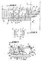
- Figure 1 is a very schematic and partial side view of a device according to the principles of the invention.
- Figure 2 is a top view, also schematic and partial, of this device.
- Figure 3 is an end view, along arrow III of Figure 1 of two clamp holder members.
- FIG. 4 is a diagrammatic view in elevation, along arrow IV of FIG. 2, of the end of the clamp-carrying members entering the sterile enclosure of the machine for packaging the containers and associated means allowing the removal of the lids on the containers by means of receptacles.
- Figure 5 is an enlarged view in axial section of a receptacle with the essential elements associated with it.
- Figure 6 is a schematic view illustrating the sequence of clamping operations allowing the routing of the lids in the sterile container packaging machine.
- a device essentially consists of a frame 1 with horizontal beams 2 supporting a plurality of clamp-carrying members, capable of conveying lids O to a machine for packaging containers or cups R comprising in particular means for conveying, filling and heat-sealing these containers which have not been shown since they are not part of the present invention, and which operate in a sterile enclosure E.
- the horizontal frame 1 with its clamp-carrying members forms a sort of gateway for the lids O, this gateway being supported at one end by a frame 3 resting on the ground, and at its other end by the machine or enclosure E for conditioning sterile R containers.
- the chassis 1 supports, by means of crosspieces 4 connecting the beams 2, several pairs of clamp-carrying members, three according to the example shown, and which are identified respectively and generally in P1, P2 and P3.
- These pairs of clamp holder members have an identical structure and, for simplicity, their structure will be described below with reference only to the pair of clamp holder members P1 which is clearly visible in FIG. 3.
- One 5 of the two clip-holding members of the pair P1 is constituted by two parallel and rotary rods 6 which each comprise a succession of plates 7. It is understood that the rotation in one direction or the other of the rods 6 may cause the opening or closing of the clamp constituted by two facing plates 7, that is to say the gripping or the loosening of a cover O.
- the other clamp-carrying member 8 of the pair P1 also consists of two parallel and rotating rods 9 each comprising a succession of plates 10 opposite the plates 7, as can be seen in FIG. 3.
- the lids can be transferred from one clamp 5 to the other 8 or vice versa by actuating these clamps.
- the clamp holder 5, constituted by the two rods 6, is secured to a carriage marked at 11 in FIG. 4, and mounted to slide on the crosspieces 4 of the chassis 1.
- the clamp holder 5 may be animated, in its longitudinal direction, with an alternating movement which will be described in detail below with regard to operation.
- the other clamp-carrying member 8 is integral with the crosspieces 4 and remains fixed in translation.
- the clamp holder 5 is movable relative to the other clamp holder 8 fixed on the frame 1, it being understood that the two rods 6, 9 constituting each clamp holder can be rotated in one direction or the other.
- the three pairs of clamp-holding members P1, P2, P3 operate in the same way and penetrate at one end into the sterile enclosure E of the packaging machine, as seen on the right-hand side of FIGS. 1 and 2.
- the other end of these clamp-carrying members is functionally connected to the frame 3 which will now be described.
- the two rods 6 of the clamp-carrying member 5 can be driven in rotation by a jack shown diagrammatically in V1 in FIG. 2, and which is integral with the chassis 1, while the two rods 9 of the other clamp holder 8, which are, as said above, fixed in translation can be controlled in rotation by another jack V2.
- the cylinders V1 and V2 respectively control the opening and closing of the clamps 5 and 8.
- the frame 3 essentially comprises a store 12 of stacked lids O, a slide 13 the displacement of which allows rotation in one direction or the other of suction cups 14 capable of gripping the lids O in the magazine 12 and of transferring them to the gripper-carrying members, and a motorcycle group -reducer M allowing the actuation of the slide 13, and also the reciprocating and synchronous movement of the gripper holder member 5, and obviously also of the movable gripper holder member of the other pairs of gripper holder members P2 and P3.
- the geared motor group M controls the rotation of an annular cam track 15 which, by means of a succession of articulated links L, allows horizontal translation and in a reciprocating movement, of the carriage 11, that is to say of the clamp-holder member 5 consisting of two parallel and rotary rods 6. Also, the geared motor group M controls, via an eccentric marked at 16 in FIG. 1, a set of levers Q capable of causing the vertical and reciprocating movement of the slide 13 carrying the suction cups 14.
- a system for sterilizing the lids O retained by the clamp-holding members this system possibly being constituted for example by a source of ultraviolet radiation or by a spraying of peroxide. of hydrogen in a tunnel identified in T surrounding the gateway for the lids O and sealingly connecting the frame 3 to the sterile enclosure E.
- a receptacle capable of receiving, by gravity the lids O, when at the end of the journey, they are released by the plates 7 of the clamp holder 5.
- the or rather the receptacles 16 are supported by a bar or the like 17 actuated vertically by the carriage 11 supporting the clamp-carrying member 5 and which, as said above, can be subjected to an alternating movement by virtue of the path cam 15 driven by the gear motor group M.
- the vertical displacement of the bar 17 supporting the receptacles 16 can be achieved by levers 18 articulated at 18a on the frame 1 and at 18b on said bar, the end of these levers being able to be actuated by cams or the like 19 integral with the carriage 11.
- pushers 20a are provided for pushing the containers R above the bar 20 of the conveyor which transports them into the sterile enclosure E.
- each receptacle 16 has a substantially cylindrical shape and comprises on the one hand two opposite slots 22 allowing the passage of the welding head 21, and on the other hand lugs 23 of temporary retention d 'a cover O released by the end of the clamp holder member 5 remaining in the sterile enclosure E of the container packaging machine.
- the magazine 12 comprises two lines of three stacks of lids each stacked, so that the movable clamp-holder member 5 can simultaneously grasp two lids such as A (FIG. 6), and therein will be the same for the other pairs P2, P3 of clip-holding members.
- the pairs of clamp-holding members P1, P2, P3 penetrate the sterile enclosure E along an increasing length, so as to deposit lids O in pairs (which lids have have been sterilized during their journey in the tunnel T to the sterile enclosure E) as the support plates 20 of the containers R advance in the sterile enclosure E.
- the suction cups 14 firstly enter two lids O in the magazine 12 and then present them in front of two clamps of the clamp holder member 5 (each clamp being constituted by two plates 7 facing each other), which clamps will grip these two lids as seen in A in Figure 6.
- the gripping of the lids can only be done after movement of the clamp holder member 5 along arrow F, towards the frame 3, so that it is thus possible to grasp the lids released by the suction cups 14.
- the clip-holding member 5 is moved along the arrow H, as can still be seen in FIG. 6, so that after the two caps A have been released by the clips of the device 5, these two caps can be again pinched or taken up by two clamps of the member 8 which is fixed in translation.
- the member 5 moves back or returns to its initial position along the arrow I to grasp from the suction cups 14 two other lids identified at B. It should be noted here that by pinching the two lids B, the following two clamps of the member 5 will simultaneously pinch the two lids A waiting and already gripped by the clamps of member 8.
- the clamps of the member 8 are then closed to retain the four lids A, B, while the clamps of the member 5 are open.
- the member 5 can again move back or return to the frame 3 along the arrow K to enter from the suction cups 4 two other lids such as C and the sequence of operations above begins again.
- the lid O provisionally fixed on the container will pass under a heat-sealing head (not shown) which will permanently close the containers.
- pairs of clamp-holding members P2, P3 will carry out the same sequence of operations as described above with respect to the pair of clamp-holding members P1, which means, if we refer in FIG. 2, that six containers carried by a plate such as 20 will have received all six a cover O after having passed under the ends of the three pairs of clip-holding members P1, P2, P3 which, each will allow the removal of two covers in a sterile atmosphere in the packaging enclosure E.
Landscapes
- Engineering & Computer Science (AREA)
- Mechanical Engineering (AREA)
- Closing Of Containers (AREA)
- Packaging Of Special Articles (AREA)
Abstract
Description
La présente invention a essentiellement pour objet un procédé de transfert d'opercules ou couvercles quelconques dans une machine de conditionnement stérile de récipients et tels que par exemple des gobelets.The present invention essentially relates to a method for transferring any lids or lids in a sterile packaging machine for containers and such as for example cups.
Elle vise également un dispositif pour l'exécution de ce procédé. Un tel procédé et un tel dispositif sont connus du document US-3.687.261 correspondant au préambule des revendications 1 et 3.It also relates to a device for the execution of this process. Such a method and such a device are known from document US Pat. No. 3,687,261 corresponding to the preamble of claims 1 and 3.
On connaît déjà, d'une manière générale, des procédés de transfert d'opercules ou couvercles dans une machine de conditionnement de récipients, et qui consistent essentiellement à saisir les opercules pour pouvoir les acheminer ensuite vers la machine dans une enceinte stérile où ils sont déposés puis thermoscellés sur lesdits récipients qui peuvent contenir un produit ou une denrée alimentaire quelconque.There are already known, in general, methods of transferring lids or lids in a container packaging machine, which essentially consist of gripping the lids so that they can then be conveyed to the machine in a sterile enclosure where they are deposited then heat-sealed on said containers which may contain any product or foodstuff.
Toutefois, ces procédés présentent des inconvénients en ce que notamment les moyens mécaniques assurant la préhension et le transfert des opercules effectuent nécessairement un certain trajet entre l'atmosphère extérieure non stérile et l'enceinte stérile de la machine où sont conditionnés les récipients, de sorte que, finalement, la stérilité de l'enceinte est détruite ou à tout le moins altérée ce qui, comme on le comprend, est préjudiciable à la qualité des produits conditionnés.However, these methods have drawbacks in that in particular the mechanical means ensuring the gripping and the transfer of the lids necessarily effect a certain path between the non-sterile external atmosphere and the sterile enclosure of the machine where the containers are conditioned, so that, finally, the sterility of the enclosure is destroyed or at the very least altered, which, as we understand, is detrimental to the quality of the packaged products.
Il convenait donc de proposer un procédé et un dispositif de transfert d'opercules qui remédie aux inconvénients ci-dessus, c'est-à-dire qui résoud le problème du maintien de la stérilité de l'enceinte de conditionnement des récipients en cas de convoyage d'opercules depuis l'extérieur vers l'intérieur de cette enceinte stérile.It was therefore appropriate to propose a method and a device for transferring lids which overcomes the above drawbacks, that is to say which resolves the problem of maintaining the sterility of the container packaging enclosure in the case of conveying of lids from the outside to the inside of this sterile enclosure.
A cet effet, l'invention a pour objet un procédé selon la revendication 1.To this end, the invention relates to a method according to claim 1.
On comprend donc déjà que le transfert d'une pince à l'autre des opercules permettra un acheminement progressif et mécaniquement sûr et fiable des opercules vers la machine, sans parler du fait que ces opercules pourront présenter des dimensions et des formes quelconques sans aucun inconvénient, c'est-à-dire sans nuire à la fiabilité du procédé.It is therefore already understood that the transfer from one gripper to the other of the lids will allow a progressive and mechanically safe and reliable routing of the lids to the machine, not to mention the fact that these lids can have any dimensions and shapes without any disadvantage. , that is to say without harming the reliability of the process.
Suivant une autre caractéristique de ce procédé, chaque opercule est déposé dans la machine de conditionnement sur un réceptacle sous lequel on pousse un récipient à obturer, et on effectue un soudage préalable et ponctuel de l'opercule sur le récipient tout en dégageant cet opercule du réceptacle par poussée sur le dessus de l'opercule, ce après quoi on effectue le thermoscellage de l'opercule sur le récipient.According to another characteristic of this process, each cover is deposited in the packaging machine on a receptacle under which a container is pushed to be closed, and a preliminary and punctual welding of the cover on the container is carried out while releasing this cover from the receptacle by pushing on the top of the cover, after which the seal is carried out on the container.
L'invention vise encore un dispositif pour la mise en oeuvre du procédé répondant aux caractéristiques ci-dessus, et caractérisé en ce qu'il comprend au moins deux organes porte-pinces allongés sensiblement parallèles et pénètrant par une extrémité dans une enceinte de conditionnement stérile de récipients, l'un de ces organes pouvant être animé, suivant sa direction longitudinale, d'un mouvement alternatif par rapport à l'autre organe porte-pinces qui demeure fixe en translation.The invention also relates to a device for implementing the method corresponding to the above characteristics, and characterized in that it comprises at least two elongated gripper-carrying members which are substantially parallel and penetrate at one end into a sterile packaging enclosure. of receptacles, one of these members being able to be driven, in its longitudinal direction, with a reciprocating movement relative to the other clamp-holding member which remains fixed in translation.
On observera déjà ici que l'extrémité de l'organe porte-pinces fixe et de l'organe porte-pinces mobile pénètrant dans l'enceinte stérile de la machine, demeure dans cette enceinte stérile, de sorte que la stérilité de cette enceinte est préservée, ce qui ne serait pas le cas si le transfert des opercules était effectué par des moyens mécaniques passant de l'extérieur vers l'intérieur de l'enceinte stérile de conditionnement des récipients.It will already be observed here that the end of the fixed clamp holder and of the movable clamp holder member entering the sterile enclosure of the machine, remains in this sterile enclosure, so that the sterility of this enclosure is preserved, which would not be the case if the transfer of the lids was carried out by mechanical means passing from the outside to the inside of the sterile enclosure for packaging the containers.
Le dispositif selon cette invention est encore caractérisé en ce que chaque organe porte-pinces est constitué par deux tiges parallèles et rotatives comportant chacune une succession de platines ou analogues qui sont en vis-à-vis entre les deux organes porte-pinces.The device according to this invention is further characterized in that each clamp-holder member is constituted by two parallel and rotary rods each comprising a succession of plates or the like which are opposite one another between the two clamp-holder members.
Suivant une autre caractéristique de ce dispositif, l'extrémité des organes porte-pinces ou tiges précitées, opposée à celle pénètrant dans l'enceinte de conditionnement, est raccordée à un bâti comportant un magasin d'opercules, un système de transfert par ventouses ou analogues des opercules du magasin vers l'organe porte-pinces mobile et des moyens d'actionnement dudit système de transfert et dudit organe porte-pinces mobile.According to another characteristic of this device, the end of the aforesaid clamps or rods members, opposite to that entering the packaging enclosure, is connected to a frame comprising a magazine for lids, a transfer system by suction cups or analogs of the lids of the store towards the movable gripper-carrying member and of means for actuating said transfer system and said movable gripper-holding member.
On précisera encore ici que les deux organes porte-pinces forment entre le bâti précité et l'enceinte de conditionnement des récipients une passerelle sous laquelle est agencé un système de stérilisation des opercules pendant leur parcours, et qui est entourée par un tunnel reliant de façon étanche le bâti à l'enceinte de conditionnement.It will also be specified here that the two clamp-carrying members form, between the aforementioned frame and the container packaging enclosure, a gateway under which is arranged a system for sterilizing the lids during their journey, and which is surrounded by a tunnel connecting waterproof the frame to the conditioning enclosure.
Dans l'enceinte de conditionnement, et en dessous de l'extrémité des deux organes porte-pinces pénètrant dans cette enceinte, est prévue au moins une barre supportant au moins un réceptacle pour les opercules et actionnable verticalement par un chariot portant l'organe porte-pinces mobile.In the packaging enclosure, and below the end of the two clamp-carrying members entering this enclosure, at least one bar is provided supporting at least one receptacle for the lids and actuated vertically by a carriage carrying the support member - mobile clamps.
Suivant encore une autre caractéristique, la barre précitée est actionnable par l'intermédiaire d'au moins un levier ou analogue et est interposée entre des moyens de poussée des récipients et une tête de soudage préalable et ponctuel des opercules sur les récipients.According to yet another characteristic, the aforementioned bar can be actuated by means of at least one lever or the like and is interposed between means for pushing the containers and a head for prior and punctual welding of the lids on the containers.
Mais d'autres caractéristiques et avantages de l'invention apparaîtront mieux dans la description détaillée qui suit et se réfère aux dessins annexés, donnés uniquement à titre d'exemple, et dans lesquels :However, other characteristics and advantages of the invention will appear better in the detailed description which follows and refers to the appended drawings, given solely by way of example, and in which:
La figure 1 est une vue de côté très schématique et partielle d'un dispositif conforme aux principes de l'invention.Figure 1 is a very schematic and partial side view of a device according to the principles of the invention.
La figure 2 est une vue de dessus, également schématique et partielle, de ce dispositif.Figure 2 is a top view, also schematic and partial, of this device.
La figure 3 est une vue en bout, suivant la flèche III de la figure 1 de deux organes porte-pinces.Figure 3 is an end view, along arrow III of Figure 1 of two clamp holder members.
La figure 4 est une vue schématique et en élévation, suivant la flèche IV de la figure 2, de l'extrémité des organes porte-pinces pénètrant dans l'enceinte stérile de la machine de conditionnement des récipients et des moyens associés permettant la dépose des opercules sur les récipients par l'intermédiaire de réceptacles.FIG. 4 is a diagrammatic view in elevation, along arrow IV of FIG. 2, of the end of the clamp-carrying members entering the sterile enclosure of the machine for packaging the containers and associated means allowing the removal of the lids on the containers by means of receptacles.
La figure 5 est une vue agrandie et en coupe axiale d'un réceptacle avec les éléments essentiels qui lui sont associés.Figure 5 is an enlarged view in axial section of a receptacle with the essential elements associated with it.
La figure 6 est une vue schématique illustrant la séquence des opérations de pinçage permettant l'acheminement des opercules dans la machine de conditionnement stérile des récipients.Figure 6 is a schematic view illustrating the sequence of clamping operations allowing the routing of the lids in the sterile container packaging machine.
En se reportant notamment aux figures 1 et 2, on voit qu'un dispositif conforme à cette invention est essentiellement constitué d'un châssis 1 avec poutres horizontales 2 supportant une pluralité d'organes porte-pinces, susceptibles d'acheminer des opercules O vers une machine de conditionnement de récipients ou gobelets R comprenant notamment des moyens de convoyage, de remplissage et de thermoscellage de ces récipients qui n'ont pas été représentés puisqu'ils ne font pas partie de la présente invention, et qui fonctionnent dans une enceinte stérile E.Referring in particular to FIGS. 1 and 2, it can be seen that a device according to this invention essentially consists of a frame 1 with
Le châssis horizontal 1 avec ses organes porte-pinces forme en quelque sorte une passerelle pour les opercules O, cette passerelle étant supportée à une extrémité par un bâti 3 reposant sur le sol, et à son autre extrémité par la machine ou enceinte E de conditionnement stérile des récipients R.The horizontal frame 1 with its clamp-carrying members forms a sort of gateway for the lids O, this gateway being supported at one end by a frame 3 resting on the ground, and at its other end by the machine or enclosure E for conditioning sterile R containers.
Comme on le voit bien sur les figures 1 à 3, le châssis 1 supporte, par l'intermédiaire de traverses 4 reliant les poutres 2, plusieurs paires d'organes porte-pinces, trois suivant l'exemple représenté, et qui sont repérées respectivement et d'une manière générale en P₁, P₂ et P₃. Ces paires d'organes porte-pinces présentent une structure identique et, pour plus de simplicité, on décrira ci-après leur structure en se référant seulement à la paire d'organes porte-pinces P₁ qui est bien visible sur la figure 3.As can be seen in FIGS. 1 to 3, the chassis 1 supports, by means of crosspieces 4 connecting the
L'un 5 des deux organes porte-pinces de la paire P₁ est constitué par deux tiges 6 parallèles et rotatives qui comportent chacune une succession de platines 7. On comprend que la rotation dans un sens ou dans l'autre des tiges 6 pourra provoquer l'ouverture ou la fermeture de la pince constituée par deux platines 7 en regard, c'est-à-dire la préhension ou le relâchement d'un opercule O.One 5 of the two clip-holding members of the pair P₁ is constituted by two parallel and
L'autre organe porte-pinces 8 de la paire P₁ se compose lui aussi de deux tiges parallèles et rotatives 9 comportant chacune une succession de platines 10 en regard des platines 7, comme on le voit bien sur la figure 3. On comprend donc déjà qu'on pourra transférer les opercules d'une pince 5 à l'autre 8 ou inversement par actionnement de ces pinces.The other clamp-carrying member 8 of the pair P₁ also consists of two parallel and rotating rods 9 each comprising a succession of
L'organe porte-pinces 5, constitué par les deux tiges 6, est solidaire d'un chariot repéré en 11 sur la figure 4, et monté coulissant sur les traverses 4 du châssis 1. Ainsi, l'organe porte-pinces 5 pourra être animé, suivant sa direction longitudinale, d'un mouvement alternatif que l'on décrira en détail plus loin à propos du fonctionnement.The
Par contre, l'autre organe porte-pinces 8 est solidaire des traverses 4 et demeure fixe en translation. En d'autres termes, l'organe porte-pinces 5 est mobile par rapport à l'autre organe porte-pinces 8 fixé sur le châssis 1, étant bien entendu que les deux tiges 6, 9 constituant chaque organe porte-pinces peuvent être entraînées en rotation dans un sens ou dans l'autre.On the other hand, the other clamp-carrying member 8 is integral with the crosspieces 4 and remains fixed in translation. In other words, the
Les trois paires d'organes porte-pinces P₁, P₂, P₃ fonctionnent de la même façon et pénètrent par une extrémité dans l'enceinte stérile E de la machine de conditionnement, comme on le voit sur la partie droite des figures 1 et 2. L'autre extrémité de ces organes porte-pinces est fonctionnellement raccordée au bâti 3 qui sera décrit maintenant.The three pairs of clamp-holding members P₁, P₂, P₃ operate in the same way and penetrate at one end into the sterile enclosure E of the packaging machine, as seen on the right-hand side of FIGS. 1 and 2. The other end of these clamp-carrying members is functionally connected to the frame 3 which will now be described.
On observera tout d'abord que les deux tiges 6 de l'organe porte-pinces 5 peuvent être entraînées en rotation par un vérin montré schématiquement en V1 sur la figure 2, et qui est solidaire du châssis 1, tandis que les deux tiges 9 de l'autre organe porte-pinces 8, qui sont, comme dit plus haut, fixes en translation peuvent être commandées en rotation par un autre vérin V2. En bref, les vérins V1 et V2 commandent respectivement l'ouverture et la fermeture des pinces 5 et 8.First of all, it will be observed that the two
Le bâti 3 comprend essentiellement un magasin 12 d'opercules empilés O, un coulisseau 13 dont le déplacement permet la rotation dans un sens ou dans l'autre de ventouses 14 susceptibles de saisir les opercules O dans le magasin 12 et de les transférer aux organes porte-pinces, et un groupe moto-réducteur M permettant l'actionnement du coulisseau 13, et également le déplacement alternatif et en synchronisme de l'organe porte-pinces 5, et évidemment aussi de l'organe porte-pinces mobile des autres paires d'organes porte-pinces P₂ et P₃.The frame 3 essentially comprises a
Plus précisément, et comme on le voit bien sur la figure 1, le groupe moto-réducteur M commande la rotation d'un chemin de came annulaire 15 qui, par l'intermédiaire d'une succession de biellettes articulées L, permet la translation horizontale et suivant un mouvement alternatif, du chariot 11, c'est-à-dire de l'organe porte-pinces 5 se composant des deux tiges parallèles et rotatives 6. Egalement, le groupe moto-réducteur M commande, par l'intermédiaire d'un excentrique repéré en 16 sur la figure 1, un jeu de leviers Q susceptibles de provoquer le déplacement vertical et alternatif du coulisseau 13 portant les ventouses 14.More precisely, and as can be seen in FIG. 1, the geared motor group M controls the rotation of an
On a montré schématiquement, par des flèches G sur la figure 1, un système de stérilisation des opercules O retenus par les organes porte-pinces, ce système pouvant être constitué par exemple par une source de rayonnement ultra-violet ou par une pulvérisation de peroxyde d'hydrogène dans un tunnel repéré en T entourant la passerelle pour les opercules O et reliant de façon étanche le bâti 3 à l'enceinte stérile E.We have shown schematically, by arrows G in FIG. 1, a system for sterilizing the lids O retained by the clamp-holding members, this system possibly being constituted for example by a source of ultraviolet radiation or by a spraying of peroxide. of hydrogen in a tunnel identified in T surrounding the gateway for the lids O and sealingly connecting the frame 3 to the sterile enclosure E.
En se reportant maintenant aux figures 4 et 5, on voit en 16 un réceptacle susceptible de recevoir, par gravité les opercules O, lorsqu'en fin de parcours, ils sont relâchés par les platines 7 de l'organe porte-pinces 5.Referring now to Figures 4 and 5, we see at 16 a receptacle capable of receiving, by gravity the lids O, when at the end of the journey, they are released by the
Le ou plutôt les réceptacles 16 sont supportés par une barre ou analogue 17 actionnable verticalement par le chariot 11 supportant l'organe porte-pinces 5 et qui, comme on l'a dit plus haut, peut être soumis à un mouvement alternatif grâce au chemin de came 15 entraîné par le groupe moto-réducteur M.The or rather the
Plus précisément, le déplacement vertical de la barre 17 supportant les réceptacles 16 peut être réalisé par des leviers 18 articulés en 18a sur le châssis 1 et en 18b sur ladite barre, l'extrémité de ces leviers pouvant être actionnée par des cames ou analogues 19 solidaires du chariot 11.More specifically, the vertical displacement of the
Sous la barre 17 portant les réceptacles 16, des poussoirs 20a sont prévus pour pousser les récipients R au-dessus de la barre 20 du convoyeur qui les transporte dans l'enceinte stérile E.Under the
Au-dessus de la barre 17 supportant les réceptacles 16, est prévue une tête 21 de soudage préalable et ponctuel des opercules O sur les récipients R, avant que ceux-ci soient définitivement obturés ultérieurement par une tête de thermoscellage (non représentée).Above the
Comme on le voit bien sur la figure 5, chaque réceptacle 16 présente une forme sensiblement cylindrique et comporte d'une part deux fentes opposées 22 permettant le passage de la tête de soudage 21, et d'autre part des ergots 23 de retenue provisoire d'un opercule O libéré par l'extrémité de l'organe porte-pinces 5 demeurant dans l'enceinte stérile E de la machine de conditionnement des récipients.As can be seen in FIG. 5, each
Mais, pour une meilleure compréhension de l'invention, on décrira ci-après le fonctionnement du dispositif qui vient d'être décrit en se reportant plus particulièrement au schéma de la figure 6.However, for a better understanding of the invention, the operation of the device which has just been described will be described below with particular reference to the diagram in FIG. 6.
Suivant l'exemple de réalisation représenté, le magasin 12 comporte deux lignes de trois piles d'opercules empilés chacune, de sorte que l'organe porte-pinces mobile 5 pourra saisir simultanément deux opercules tels que A (figure 6), et il en sera de même pour les autres paires P₂, P₃ d'organes porte-pinces. On observera ici, en se reportant à la figure 2 que les paires d'organes porte-pinces P₁, P₂, P₃ pénètrent dans l'enceinte stérile E suivant une longueur croissante, de façon à déposer des opercules O par paires (lesquels opercules ont été stérilisés pendant leur parcours dans le tunnel T jusqu'à l'enceinte stérile E) au fur et à mesure de l'avancement des plaques-support 20 des récipients R dans l'enceinte stérile E.According to the exemplary embodiment shown, the
Mais, comme pour la description ci-avant de la structure du dispositif de l'invention, on décrira ci-après le fonctionnement en ne considérant que les deux organes porte-pinces 5 et 8, puisque les autres organes porte-pinces appartenant aux paires P₂ et P₃ sont structurellement les mêmes et fonctionnent de la même façon.But, as for the description above of the structure of the device of the invention, the operation will be described below by considering only the two clamp-holding
Les ventouses 14 viennent tout d'abord saisir deux opercules O dans le magasin 12 pour ensuite les présenter en face de deux pinces de l'organe porte-pinces 5 (chaque pince étant constituée par deux platines 7 en regard), lesquelles pinces saisiront ces deux opercules comme on le voit en A sur la figure 6. Bien entendu, la préhension des opercules ne peut se faire qu'après déplacement de l'organe porte-pinces 5 suivant la flèche F, vers le bâti 3, de façon à pouvoir ainsi saisir les opercules relâchés par les ventouses 14.The
Ensuite, l'organe porte-pinces 5 est déplacé suivant la flèche H, comme on le voit encore sur la figure 6, de façon qu'après relâchement des deux opercules A par les pinces de l'organe 5, ces deux opercules puissent être à nouveau pincés ou repris par deux pinces de l'organe 8 qui est fixe en translation.Then, the clip-
Ensuite, l'organe 5 recule ou revient à sa position initiale suivant la flèche I pour saisir depuis les ventouses 14 deux autres opercules repérés en B. Il est à noter ici qu'en pinçant les deux opercules B, les deux pinces suivantes de l'organe 5 pinceront simultanément les deux opercules A en attente et déjà saisis par les pinces de l'organe 8.Then, the
Les pinces de l'organe 8 retenant les opercules A sont ensuite ouvertes, et l'organe 5 peut alors être translaté vers la droite de la figure 6 suivant la flèche J comme montré sur la figure 6.The clips of the member 8 retaining the lids A are then opened, and the
Les pinces de l'organe 8 sont alors fermées pour retenir les quatres opercules A, B, tandis que les pinces de l'organe 5 sont ouvertes.The clamps of the member 8 are then closed to retain the four lids A, B, while the clamps of the
Ainsi, l'organe 5 peut à nouveau reculer ou revenir vers le bâti 3 suivant la flèche K pour saisir depuis les ventouses 4 deux autres opercules tels que C et la séquence des opérations ci-dessus recommence.Thus, the
On comprend donc que par passage des opercules d'un organe porte-pinces à l'autre et par déplacement alternatif de l'organe 5 par rapport à l'organe 8 qui demeure immobile en translation, on obtiendra un acheminement pas à pas des opercules vers l'enceinte stérile E où ils seront déposés par paires, par gravité et par l'extrémité de l'organe porte-pinces 5 dans deux réceptacles tels que 16 à l'intérieur desquels ils seront retenus par les ergots 23, comme on le voit bien sur la figure 5.It is therefore understood that by passing the lids from one clamp-carrying member to the other and by reciprocating movement of the
A ce stade, il se produira un mouvement simultané de descente de la tête de soudage 21 qui fera passer l'opercule O au-delà des ergots 23, et un mouvement de montée des récipients R, grâce aux poussoirs 20a, de sorte qu'on réalisera un soudage préalable et ponctuel dudit opercule sur le bord supérieur du récipient R.At this stage, there will be a simultaneous downward movement of the
Ensuite, l'opercule O provisoirement fixé sur le récipient, passera sous une tête de thermoscellage (non représentée) qui obturera définitivement les récipients.Then, the lid O provisionally fixed on the container, will pass under a heat-sealing head (not shown) which will permanently close the containers.
On rappellera ici que les paires d'organes porte-pinces P₂, P₃ effectueront la même séquence d'opérations que décrite ci-dessus à propos de la paire d'organes porte-pinces P₁, ce qui signifie, si l'on se reporte à la figure 2, que six récipients portés par une plaque telle que 20 auront reçu tous les six un opercule O après être passés sous les extrémités des trois paires d'organes porte-pinces P₁, P₂, P₃ qui, chacun permettront la dépose de deux opercules en atmosphère stérile dans l'enceinte de conditionnement E.It will be recalled here that the pairs of clamp-holding members P₂, P₃ will carry out the same sequence of operations as described above with respect to the pair of clamp-holding members P₁, which means, if we refer in FIG. 2, that six containers carried by a plate such as 20 will have received all six a cover O after having passed under the ends of the three pairs of clip-holding members P₁, P₂, P₃ which, each will allow the removal of two covers in a sterile atmosphere in the packaging enclosure E.
On a donc réalisé suivant l'invention un procédé et un dispositif de transfert d'opercules utilisant un nombre minimum de pièces mécaniques qui effectuent la dépose et qui demeurent toujours dans l'enceinte stérile E de conditionnement, de sorte que la stérilité de ladite enceinte ne risque en aucun cas d'être détruite ou même altérée.We therefore carried out according to the invention a method and a device for transfer of lids using a minimum number of mechanical parts which carry out the removal and which always remain in the sterile enclosure E for packaging, so that the sterility of said enclosure in no case risks to be destroyed or even altered.
Claims (8)
- Method of transferring lids, covers or the like into a machine for the sterile conditioning of any containers whatsoever, of the type consisting in gripping the lids for then carrying them towards the machine where they are deposited in a sterile atmosphere upon the containers containing any product or foodstuff whatsoever and which has to be closed by the said lids, characterized in that for conveying the lids (O) towards the machine, one nips each lid with a first pair of tongs (7, 7) forming part of a first elongated tongs-carrying member (5) which may be driven in the longitudinal direction according to a reciprocating motion, one then displaces the nipped lid in the direction towards the machine (arrow H), one takes up again the lid with a second pair of tongs (10, 10) in confronting relation to the first pair of tongs, the second pair of tongs forming part of a second elongated tongs-carrying member (8) stationary in translation with respect to the first member, one releases the lid from the first pair of tongs which one makes come back to its initial position (arrow I) in order that it may grip a second lid at the same time as one nips with the assistance of a third pair of tongs (7, 7) forming part of the first member (5) the standby lid already gripped by the second pair of tongs (10, 10), one opens this second pair of tongs, one transfers both lids gripped by the first and third pairs of tongs, respectively, in the direction towards the machine, one then takes up again these two lids with two pairs of tongs (10, 10) forming part of the second member (8) and in confronting relation to the first and third pairs of tongs, and so on.
- Method according to claim 1, characterized in that in each lid is deposited in the conditioning machine upon a container underneath which one pushes a container to be closed and one effects a previous pinpoint welding of the lid onto the container while disengaging this lid from the container through a thrust upon the top of the lid whereafter one effects the heat-sealing of the lid onto the container.
- Device for carrying out of the method according to claim 1 or 2, characterized in that it comprises at least two substantially parallel, elongated, tongs-carrying members (5, 8) penetrating with one end into an enclosure (E) for the sterile conditioning of containers, one (5) of these members may be driven along its longitudinal direction according to a reciprocating motion with respect to the other tongs-carrying member (8) which remains stationary in translation.
- Device according to claim 3, characterized in that each tongs-carrying member (5, 8) is constituted by two parallel rotary rods (6, 9) successively comprising each one plates or the like (7, 10) which are in front of both tongs-carrying members.
- Device according to claim 3 or 4, characterized in that that end of the tongs-carrying members (5, 8) or aforesaid rods (6, 9), which is opposite to that penetrating into the conditioning enclosure (E) is connected to a frame (3) comprising a store (12) for lids (O), a system (14) for transferring lids (0) with suction cups from the store (12) towards the movable tongs-carrying member (5) and means (M, L, Q) for the actuation of the said transfer system and of the said movable tongs-carrying member.
- Device according to one of claims 3 to 5, characterized in that both tongs-carrying members (5, 8) form between the frame (3) and the conditioning machine a bridge under which is arranged a system (G) for the sterilization of the lids (0) during their travel and which is surrounded by a tunnel (T) tightly connecting the frame (3) to the sterile conditioning enclosure (E).
- Device according to one of claims 3 to 6, characterized in that in the conditioning machine and underneath the end of both tongs-carrying members (5, 8) is provided at least one bar (17) supporting at least one container (16) for the lids (0) and vertically operable by a carriage (11) carrying the movable tongs-carrying member (5).
- Device according to claim 7, characterized in that the aforesaid bar (17) is operable through the medium of at least one lever or the like (18) and is interposed between means (20a) for pushing the containers (R) and a head (21) for the previous pinpoint welding of the lids (0) onto the containers (R).
Applications Claiming Priority (2)
| Application Number | Priority Date | Filing Date | Title |
|---|---|---|---|
| FR8915263A FR2654702B1 (en) | 1989-11-21 | 1989-11-21 | METHOD AND DEVICE FOR TRANSFERRING LIDS, LIDS OR THE LIKE IN A STERILE CONTAINER PACKAGING MACHINE. |
| FR8915263 | 1989-11-21 |
Publications (2)
| Publication Number | Publication Date |
|---|---|
| EP0429318A1 EP0429318A1 (en) | 1991-05-29 |
| EP0429318B1 true EP0429318B1 (en) | 1993-08-04 |
Family
ID=9387604
Family Applications (1)
| Application Number | Title | Priority Date | Filing Date |
|---|---|---|---|
| EP90403017A Expired - Lifetime EP0429318B1 (en) | 1989-11-21 | 1990-10-25 | Method and apparatus for transferring lids, covers or similar in a machine for sterile packaging of containers |
Country Status (8)
| Country | Link |
|---|---|
| US (1) | US5123229A (en) |
| EP (1) | EP0429318B1 (en) |
| AT (1) | ATE92418T1 (en) |
| DE (2) | DE69002588T2 (en) |
| DK (1) | DK0429318T3 (en) |
| ES (1) | ES2027622T3 (en) |
| FR (1) | FR2654702B1 (en) |
| GR (1) | GR920300001T1 (en) |
Families Citing this family (8)
| Publication number | Priority date | Publication date | Assignee | Title |
|---|---|---|---|---|
| US5438814A (en) * | 1993-09-21 | 1995-08-08 | Webber Manufacturing Co., Inc. | Bucket lidding system for continuously conveying buckets |
| US5447699A (en) * | 1993-11-17 | 1995-09-05 | The West Company | Combination container for holding sterilized elements and a sterilizable transfer port |
| FR2736041B1 (en) * | 1995-06-30 | 1997-08-29 | Deep | METHOD FOR FILLING A BOTTLE, PARTICULARLY IN PLASTIC MATERIAL, WITH A LIQUID AND ASSOCIATED DEVICE |
| US5857309A (en) * | 1997-03-28 | 1999-01-12 | Tetra Laval Holdings & Finance, S.A. | Apparatus for sterilizing a spout assembly of a container |
| US6298638B1 (en) | 1997-04-21 | 2001-10-09 | Graham Packaging Company, L.P. | System for blow-molding, filling and capping containers |
| SE524200C2 (en) * | 2002-02-19 | 2004-07-06 | Trepak Internat Ab | Mechanism and method of encapsulation |
| ITPR20130017A1 (en) * | 2013-03-11 | 2014-09-12 | Gea Procomac Spa | CLOSING TREATMENT SYSTEM FOR CONTAINERS USING A STERILIZING SUBSTANCE |
| CN110562740B (en) * | 2019-10-10 | 2024-06-25 | 苏州铁近机电科技股份有限公司 | Bearing shield loading attachment |
Family Cites Families (17)
| Publication number | Priority date | Publication date | Assignee | Title |
|---|---|---|---|---|
| DE170969C (en) * | ||||
| US3501896A (en) * | 1967-05-18 | 1970-03-24 | Vonco Products Inc | Automatic heat sealing apparatus |
| US3491510A (en) * | 1967-08-01 | 1970-01-27 | Grace W R & Co | Apparatus and method for simultaneously making closures and sealing containers |
| CH494156A (en) * | 1968-07-31 | 1970-07-31 | Sig Schweiz Industrieges | Device for closing containers by means of lids formed from a film |
| GB1235057A (en) * | 1969-12-18 | 1971-06-09 | Sweetheart Plastics | Improvements in or relating to machines for filling containers with liquid |
| JPS4922746B1 (en) * | 1970-10-20 | 1974-06-11 | ||
| US3703066A (en) * | 1971-01-05 | 1972-11-21 | Maryland Cup Corp | Apparatus for feeding heat shrinkable plastic film and capping containers therewith |
| US3687261A (en) * | 1971-04-02 | 1972-08-29 | Dole James Corp | Conveying system |
| US3766709A (en) * | 1972-01-28 | 1973-10-23 | Zausner Foods Corp | Sterilizing device for container filling machines |
| US3783581A (en) * | 1972-04-18 | 1974-01-08 | Dart Ind Inc | Aseptic packaging method and machine |
| US3908340A (en) * | 1974-03-25 | 1975-09-30 | Anderson Bros Mfg Co | Apparatus for feeding and applying individual lids to containers |
| US4226072A (en) * | 1978-12-06 | 1980-10-07 | Balzer Winton E | Apparatus for applying a film lid to a cup |
| DE3437642C2 (en) * | 1984-10-13 | 1994-03-31 | Haar Maschbau Alfons | Feed device for inserting and feeding sheets into a punch |
| DE3522996A1 (en) * | 1985-06-27 | 1987-01-08 | Kolbus Gmbh & Co Kg | METHOD FOR DETERMINING STERILE SPACES AGAINST LEAKING TOXIC STERILIZING AGENTS OR INFLUENCE OF MICRO-ORGANISMS, PREFERRED TO APPLY FOR FILLING MACHINES, AND DEVICE FOR IMPLEMENTING THE METHOD |
| SE459730B (en) * | 1987-12-04 | 1989-07-31 | Kabivitrum Ab | APPLIANCES FOR FILLING AND CLOSING BOTTLES CONTAINING A NUMBER OF TREATMENT STATIONS PROVIDED IN A CYCLIC CYCLE |
| JP2655883B2 (en) * | 1988-07-26 | 1997-09-24 | 雪印乳業株式会社 | Aseptic packaging container and aseptic filling method |
| US5006028A (en) * | 1990-05-18 | 1991-04-09 | Jackson Donald T | Cam lift and carry parts transfer apparatus |
-
1989
- 1989-11-21 FR FR8915263A patent/FR2654702B1/en not_active Expired - Lifetime
-
1990
- 1990-10-25 DE DE90403017T patent/DE69002588T2/en not_active Expired - Fee Related
- 1990-10-25 EP EP90403017A patent/EP0429318B1/en not_active Expired - Lifetime
- 1990-10-25 DK DK90403017.8T patent/DK0429318T3/en active
- 1990-10-25 ES ES90403017T patent/ES2027622T3/en not_active Expired - Lifetime
- 1990-10-25 DE DE199090403017T patent/DE429318T1/en active Pending
- 1990-10-25 AT AT90403017T patent/ATE92418T1/en not_active IP Right Cessation
- 1990-11-21 US US07/616,401 patent/US5123229A/en not_active Expired - Fee Related
-
1992
- 1992-08-25 GR GR92300001T patent/GR920300001T1/en unknown
Also Published As
| Publication number | Publication date |
|---|---|
| ES2027622T3 (en) | 1994-01-01 |
| DE69002588D1 (en) | 1993-09-09 |
| EP0429318A1 (en) | 1991-05-29 |
| GR920300001T1 (en) | 1992-08-25 |
| DE429318T1 (en) | 1992-02-06 |
| DK0429318T3 (en) | 1993-12-13 |
| FR2654702B1 (en) | 1992-03-20 |
| US5123229A (en) | 1992-06-23 |
| ES2027622T1 (en) | 1992-06-16 |
| ATE92418T1 (en) | 1993-08-15 |
| DE69002588T2 (en) | 1994-02-03 |
| FR2654702A1 (en) | 1991-05-24 |
Similar Documents
| Publication | Publication Date | Title |
|---|---|---|
| EP1853482B1 (en) | Machine for automated packaging of product(s) in a cardboard box | |
| FR2465665A1 (en) | DEVICE FOR DISTRIBUTING MULTI-FILT CONTAINERS AND MACHINE USING SUCH A DEVICE | |
| FR2652529A1 (en) | ROBOT. | |
| EP0429318B1 (en) | Method and apparatus for transferring lids, covers or similar in a machine for sterile packaging of containers | |
| CH373688A (en) | Method for inserting a collapsible partition blank between rows of containers to be packaged and a machine for carrying out this method | |
| EP0286514B1 (en) | Conveyer comprising platforms specially enabling the transport of buckets | |
| EP3263469B1 (en) | Machine for extracting, shaping, filling and closing an american box | |
| CH547731A (en) | PACKAGING MACHINE. | |
| EP0434542B1 (en) | Device for packaging various products | |
| FR2911849A1 (en) | Bottle or vial introducing device, has turning unit to turn bottles by rotation of one hundred and eight degrees, and gripping unit mounted in vertical translation, where gripping unit lowers turned bottles towards open end of case | |
| FR2493805A1 (en) | Folding feed for container blanks - has powered rotary conveyor with gripping jaws to pass containers to working stations | |
| EP0577905A1 (en) | Method and device for aligning packing blanks particularly labels for cigarette packets | |
| FR2573006A1 (en) | PRINTING MACHINE | |
| EP4031454A1 (en) | Device and method for forming a container by folding | |
| EP0367881A1 (en) | Folding installation for a rectangular piece of textile | |
| FR2707597A1 (en) | Method for feeding tobacco pieces, in particular cigarettes, to a continuous packaging machine. | |
| FR2602119A1 (en) | Automatic machine for loading and unloading trays of shelf frames in the treatment of meats in general | |
| EP0220967B1 (en) | Conveyor for containers | |
| FR2528008A1 (en) | Packing feed for bottles - uses elevator to receive group suspended by neck and inverter feed gripping bottle bodies | |
| FR2750122A1 (en) | Grouping appts. for cartons delivered in single file | |
| EP0694224B1 (en) | Method and device for inserting wire extremities in components, and device for fabricating wiring harnesses | |
| EP0050083A1 (en) | Apparatus for grouping unit-containers | |
| EP0093645A1 (en) | Device for the automatic packaging of a crate with objects in a lying position | |
| FR2612487A1 (en) | Method for continuously boxing, in superposed layers, objects such as, for example, containers, and machine involving application of this method | |
| FR2612488A1 (en) | Method for automatically and continuously packaging objects such as, for example, bottles, and machine for implementing this method |
Legal Events
| Date | Code | Title | Description |
|---|---|---|---|
| PUAI | Public reference made under article 153(3) epc to a published international application that has entered the european phase |
Free format text: ORIGINAL CODE: 0009012 |
|
| AK | Designated contracting states |
Kind code of ref document: A1 Designated state(s): AT BE CH DE DK ES GB GR IT LI LU NL SE |
|
| 17P | Request for examination filed |
Effective date: 19910802 |
|
| RAP1 | Party data changed (applicant data changed or rights of an application transferred) |
Owner name: STORK DARDAINE INDUSTRIES S.A. |
|
| GBC | Gb: translation of claims filed (gb section 78(7)/1977) | ||
| TCAT | At: translation of patent claims filed | ||
| REG | Reference to a national code |
Ref country code: DE Ref legal event code: 8580 Free format text: DER ANMELDER LAUTET RICHTIG: STORK DARDAINE INDUSTRIES S.A., DREUX, FR |
|
| TCNL | Nl: translation of patent claims filed | ||
| RAP1 | Party data changed (applicant data changed or rights of an application transferred) |
Owner name: STORK DARDAINE INDUSTRIES S.A. |
|
| DET | De: translation of patent claims | ||
| 17Q | First examination report despatched |
Effective date: 19930111 |
|
| GRAA | (expected) grant |
Free format text: ORIGINAL CODE: 0009210 |
|
| AK | Designated contracting states |
Kind code of ref document: B1 Designated state(s): AT BE CH DE DK ES GB GR IT LI LU NL SE |
|
| REF | Corresponds to: |
Ref document number: 92418 Country of ref document: AT Date of ref document: 19930815 Kind code of ref document: T |
|
| REF | Corresponds to: |
Ref document number: 69002588 Country of ref document: DE Date of ref document: 19930909 |
|
| ITF | It: translation for a ep patent filed | ||
| GBT | Gb: translation of ep patent filed (gb section 77(6)(a)/1977) |
Effective date: 19931014 |
|
| REG | Reference to a national code |
Ref country code: DK Ref legal event code: T3 |
|
| EPTA | Lu: last paid annual fee | ||
| REG | Reference to a national code |
Ref country code: ES Ref legal event code: FG2A Ref document number: 2027622 Country of ref document: ES Kind code of ref document: T3 |
|
| REG | Reference to a national code |
Ref country code: GR Ref legal event code: FG4A Free format text: 3009569 |
|
| PLBE | No opposition filed within time limit |
Free format text: ORIGINAL CODE: 0009261 |
|
| STAA | Information on the status of an ep patent application or granted ep patent |
Free format text: STATUS: NO OPPOSITION FILED WITHIN TIME LIMIT |
|
| 26N | No opposition filed | ||
| EAL | Se: european patent in force in sweden |
Ref document number: 90403017.8 |
|
| PGFP | Annual fee paid to national office [announced via postgrant information from national office to epo] |
Ref country code: GB Payment date: 19951016 Year of fee payment: 6 |
|
| PGFP | Annual fee paid to national office [announced via postgrant information from national office to epo] |
Ref country code: DK Payment date: 19951025 Year of fee payment: 6 Ref country code: AT Payment date: 19951025 Year of fee payment: 6 |
|
| PGFP | Annual fee paid to national office [announced via postgrant information from national office to epo] |
Ref country code: SE Payment date: 19951026 Year of fee payment: 6 Ref country code: DE Payment date: 19951026 Year of fee payment: 6 |
|
| PGFP | Annual fee paid to national office [announced via postgrant information from national office to epo] |
Ref country code: ES Payment date: 19951027 Year of fee payment: 6 |
|
| PGFP | Annual fee paid to national office [announced via postgrant information from national office to epo] |
Ref country code: GR Payment date: 19951030 Year of fee payment: 6 |
|
| PGFP | Annual fee paid to national office [announced via postgrant information from national office to epo] |
Ref country code: NL Payment date: 19951031 Year of fee payment: 6 |
|
| PGFP | Annual fee paid to national office [announced via postgrant information from national office to epo] |
Ref country code: CH Payment date: 19951113 Year of fee payment: 6 |
|
| PGFP | Annual fee paid to national office [announced via postgrant information from national office to epo] |
Ref country code: BE Payment date: 19951213 Year of fee payment: 6 |
|
| PGFP | Annual fee paid to national office [announced via postgrant information from national office to epo] |
Ref country code: LU Payment date: 19960101 Year of fee payment: 6 |
|
| PG25 | Lapsed in a contracting state [announced via postgrant information from national office to epo] |
Ref country code: LU Free format text: LAPSE BECAUSE OF NON-PAYMENT OF DUE FEES Effective date: 19961025 Ref country code: GB Effective date: 19961025 Ref country code: DK Effective date: 19961025 Ref country code: AT Effective date: 19961025 |
|
| REG | Reference to a national code |
Ref country code: DK Ref legal event code: EBP |
|
| PG25 | Lapsed in a contracting state [announced via postgrant information from national office to epo] |
Ref country code: SE Effective date: 19961026 Ref country code: ES Free format text: LAPSE BECAUSE OF THE APPLICANT RENOUNCES Effective date: 19961026 |
|
| PG25 | Lapsed in a contracting state [announced via postgrant information from national office to epo] |
Ref country code: LI Effective date: 19961031 Ref country code: CH Effective date: 19961031 Ref country code: BE Effective date: 19961031 |
|
| BERE | Be: lapsed |
Owner name: S.A. STORK DARDAINE INDUSTRIES Effective date: 19961031 |
|
| PG25 | Lapsed in a contracting state [announced via postgrant information from national office to epo] |
Ref country code: GR Free format text: THE PATENT HAS BEEN ANNULLED BY A DECISION OF A NATIONAL AUTHORITY Effective date: 19970430 |
|
| PG25 | Lapsed in a contracting state [announced via postgrant information from national office to epo] |
Ref country code: NL Effective date: 19970501 |
|
| REG | Reference to a national code |
Ref country code: GR Ref legal event code: MM2A Free format text: 3009569 |
|
| REG | Reference to a national code |
Ref country code: CH Ref legal event code: PL |
|
| GBPC | Gb: european patent ceased through non-payment of renewal fee |
Effective date: 19961025 |
|
| NLV4 | Nl: lapsed or anulled due to non-payment of the annual fee |
Effective date: 19970501 |
|
| PG25 | Lapsed in a contracting state [announced via postgrant information from national office to epo] |
Ref country code: DE Effective date: 19970701 |
|
| EUG | Se: european patent has lapsed |
Ref document number: 90403017.8 |
|
| REG | Reference to a national code |
Ref country code: ES Ref legal event code: FD2A Effective date: 19991102 |
|
| PG25 | Lapsed in a contracting state [announced via postgrant information from national office to epo] |
Ref country code: IT Free format text: LAPSE BECAUSE OF NON-PAYMENT OF DUE FEES;WARNING: LAPSES OF ITALIAN PATENTS WITH EFFECTIVE DATE BEFORE 2007 MAY HAVE OCCURRED AT ANY TIME BEFORE 2007. THE CORRECT EFFECTIVE DATE MAY BE DIFFERENT FROM THE ONE RECORDED. Effective date: 20051025 |