EP0428679B1 - Apparat und verfahren zur befestigung eines mundstücks in eine öffnung in einem band oder einer dünnen schicht - Google Patents
Apparat und verfahren zur befestigung eines mundstücks in eine öffnung in einem band oder einer dünnen schicht Download PDFInfo
- Publication number
- EP0428679B1 EP0428679B1 EP90908757A EP90908757A EP0428679B1 EP 0428679 B1 EP0428679 B1 EP 0428679B1 EP 90908757 A EP90908757 A EP 90908757A EP 90908757 A EP90908757 A EP 90908757A EP 0428679 B1 EP0428679 B1 EP 0428679B1
- Authority
- EP
- European Patent Office
- Prior art keywords
- port
- film
- web
- rotatable
- ports
- Prior art date
- Legal status (The legal status is an assumption and is not a legal conclusion. Google has not performed a legal analysis and makes no representation as to the accuracy of the status listed.)
- Expired - Lifetime
Links
- 238000000034 method Methods 0.000 title abstract description 19
- 230000001105 regulatory effect Effects 0.000 claims abstract 2
- 230000037431 insertion Effects 0.000 claims 3
- 238000003780 insertion Methods 0.000 claims 3
- 238000004806 packaging method and process Methods 0.000 description 18
- 239000012530 fluid Substances 0.000 description 3
- 230000003213 activating effect Effects 0.000 description 1
- 238000010276 construction Methods 0.000 description 1
- 239000002537 cosmetic Substances 0.000 description 1
- 235000013365 dairy product Nutrition 0.000 description 1
- 239000003814 drug Substances 0.000 description 1
- 230000000694 effects Effects 0.000 description 1
- 235000013305 food Nutrition 0.000 description 1
- 238000012423 maintenance Methods 0.000 description 1
- 235000014101 wine Nutrition 0.000 description 1
Images

Classifications
-
- B—PERFORMING OPERATIONS; TRANSPORTING
- B29—WORKING OF PLASTICS; WORKING OF SUBSTANCES IN A PLASTIC STATE IN GENERAL
- B29C—SHAPING OR JOINING OF PLASTICS; SHAPING OF MATERIAL IN A PLASTIC STATE, NOT OTHERWISE PROVIDED FOR; AFTER-TREATMENT OF THE SHAPED PRODUCTS, e.g. REPAIRING
- B29C66/00—General aspects of processes or apparatus for joining preformed parts
- B29C66/50—General aspects of joining tubular articles; General aspects of joining long products, i.e. bars or profiled elements; General aspects of joining single elements to tubular articles, hollow articles or bars; General aspects of joining several hollow-preforms to form hollow or tubular articles
- B29C66/51—Joining tubular articles, profiled elements or bars; Joining single elements to tubular articles, hollow articles or bars; Joining several hollow-preforms to form hollow or tubular articles
- B29C66/53—Joining single elements to tubular articles, hollow articles or bars
- B29C66/532—Joining single elements to the wall of tubular articles, hollow articles or bars
- B29C66/5324—Joining single elements to the wall of tubular articles, hollow articles or bars said single elements being substantially annular, i.e. of finite length
- B29C66/53245—Joining single elements to the wall of tubular articles, hollow articles or bars said single elements being substantially annular, i.e. of finite length said articles being hollow
- B29C66/53246—Joining single elements to the wall of tubular articles, hollow articles or bars said single elements being substantially annular, i.e. of finite length said articles being hollow said single elements being spouts, e.g. joining spouts to containers
- B29C66/53247—Joining single elements to the wall of tubular articles, hollow articles or bars said single elements being substantially annular, i.e. of finite length said articles being hollow said single elements being spouts, e.g. joining spouts to containers said spouts comprising flanges
-
- B—PERFORMING OPERATIONS; TRANSPORTING
- B29—WORKING OF PLASTICS; WORKING OF SUBSTANCES IN A PLASTIC STATE IN GENERAL
- B29C—SHAPING OR JOINING OF PLASTICS; SHAPING OF MATERIAL IN A PLASTIC STATE, NOT OTHERWISE PROVIDED FOR; AFTER-TREATMENT OF THE SHAPED PRODUCTS, e.g. REPAIRING
- B29C65/00—Joining or sealing of preformed parts, e.g. welding of plastics materials; Apparatus therefor
- B29C65/02—Joining or sealing of preformed parts, e.g. welding of plastics materials; Apparatus therefor by heating, with or without pressure
-
- B—PERFORMING OPERATIONS; TRANSPORTING
- B29—WORKING OF PLASTICS; WORKING OF SUBSTANCES IN A PLASTIC STATE IN GENERAL
- B29C—SHAPING OR JOINING OF PLASTICS; SHAPING OF MATERIAL IN A PLASTIC STATE, NOT OTHERWISE PROVIDED FOR; AFTER-TREATMENT OF THE SHAPED PRODUCTS, e.g. REPAIRING
- B29C66/00—General aspects of processes or apparatus for joining preformed parts
- B29C66/01—General aspects dealing with the joint area or with the area to be joined
- B29C66/05—Particular design of joint configurations
- B29C66/10—Particular design of joint configurations particular design of the joint cross-sections
- B29C66/11—Joint cross-sections comprising a single joint-segment, i.e. one of the parts to be joined comprising a single joint-segment in the joint cross-section
- B29C66/112—Single lapped joints
-
- B—PERFORMING OPERATIONS; TRANSPORTING
- B29—WORKING OF PLASTICS; WORKING OF SUBSTANCES IN A PLASTIC STATE IN GENERAL
- B29C—SHAPING OR JOINING OF PLASTICS; SHAPING OF MATERIAL IN A PLASTIC STATE, NOT OTHERWISE PROVIDED FOR; AFTER-TREATMENT OF THE SHAPED PRODUCTS, e.g. REPAIRING
- B29C66/00—General aspects of processes or apparatus for joining preformed parts
- B29C66/01—General aspects dealing with the joint area or with the area to be joined
- B29C66/05—Particular design of joint configurations
- B29C66/10—Particular design of joint configurations particular design of the joint cross-sections
- B29C66/13—Single flanged joints; Fin-type joints; Single hem joints; Edge joints; Interpenetrating fingered joints; Other specific particular designs of joint cross-sections not provided for in groups B29C66/11 - B29C66/12
- B29C66/131—Single flanged joints, i.e. one of the parts to be joined being rigid and flanged in the joint area
-
- B—PERFORMING OPERATIONS; TRANSPORTING
- B31—MAKING ARTICLES OF PAPER, CARDBOARD OR MATERIAL WORKED IN A MANNER ANALOGOUS TO PAPER; WORKING PAPER, CARDBOARD OR MATERIAL WORKED IN A MANNER ANALOGOUS TO PAPER
- B31B—MAKING CONTAINERS OF PAPER, CARDBOARD OR MATERIAL WORKED IN A MANNER ANALOGOUS TO PAPER
- B31B70/00—Making flexible containers, e.g. envelopes or bags
- B31B70/74—Auxiliary operations
- B31B70/81—Forming or attaching accessories, e.g. opening devices, closures or tear strings
- B31B70/84—Forming or attaching means for filling or dispensing contents, e.g. valves or spouts
- B31B70/844—Applying rigid valves, spouts, or filling tubes
-
- Y—GENERAL TAGGING OF NEW TECHNOLOGICAL DEVELOPMENTS; GENERAL TAGGING OF CROSS-SECTIONAL TECHNOLOGIES SPANNING OVER SEVERAL SECTIONS OF THE IPC; TECHNICAL SUBJECTS COVERED BY FORMER USPC CROSS-REFERENCE ART COLLECTIONS [XRACs] AND DIGESTS
- Y10—TECHNICAL SUBJECTS COVERED BY FORMER USPC
- Y10T—TECHNICAL SUBJECTS COVERED BY FORMER US CLASSIFICATION
- Y10T156/00—Adhesive bonding and miscellaneous chemical manufacture
- Y10T156/17—Surface bonding means and/or assemblymeans with work feeding or handling means
- Y10T156/1702—For plural parts or plural areas of single part
- Y10T156/1712—Indefinite or running length work
- Y10T156/1734—Means bringing articles into association with web
Definitions
- the present invention relates to apparatus and methods for positioning a port in an aperture in a web of film in a packaging machine.
- Packaging machines are utilized to package a variety of products in flexible containers.
- One method for packaging a product in a flexible container is to utilize a form, fill, seal packaging machine.
- form, fill, seal packaging machines are utilized to seal pharmaceuticals, dairy products, wine, food stuffs, cosmetics, and other products in flexible containers.
- the form, fill, seal packaging machine provides an apparatus for packaging these products in an expedient manner.
- a web of heat sealable film is passed over a former or mandrel that forms the film into a tubular shape.
- the film is folded longitudinally and heat sealed along abutting longitudinal edges.
- the tubular-shaped film is then passed around a tubular fill system that deposits the product to be packaged into the tubular-shaped film.
- bags the web of film must be sealed across its width.
- side seals are typically created by a sealer that creates the second seal for one bag while making the first seal for the next bag. After the side seals are created, the web of film can then be severed between the side seals to create individual bags.
- the term "ports" includes, without limitation, fitments, valves, and other means for accessing the fluid contained within the container.
- the ports provide a means for accessing the container, either utilizing a spike or needle, or through a valve located on the port.
- the ports typically include a tubular portion for receiving a spike or needle. The tubular portion extends from a base or flange that is sealed to a web of film.
- the web of film is punched by means for creating an opening or aperture in the film.
- the tubular portion of the port is positioned within the opening and the base is sealed to the web of film. It should be noted, however, that the film can be prepunched and fed into the packaging machine in a prepunched state.
- the fitments must be delivered in juxtaposition to the film and the ports inserted through the openings or apertures in the film.
- a conveying mechanism such as a chain loop having a plurality of forks for releasably retaining the ports and by utilizing a number of pneumatic cylinders to move the ports from the chain loop and insert them into an aperture in the film.
- the unit might use two pneumatic cylinders to move the port first away from the conveying mechanism and then toward and through a hole in the film. This results in a three-step process of moving the ports to the elevator, transferring the ports to the elevator, and then urging a port upwardly into an aperture in the film.
- This prior method can result in the misalignment of the ports in the aperture in the web of film and difficulty in transferring the port from the apparatus to the film. Accordingly, the process can result in ports not being properly aligned in the film or with respect to the aperture in the web of film and therefore, when the ports are sealed to the film, a secure seal may not be effectuated or the ports may be misaligned within the film.
- the present invention provides an apparatus and method for delivering a port to an aperture in a web of film and inserting same therethrough.
- the method permits maintenance of the integrity of the original alignment of the port. Once the ports are aligned within the apparatus, they can be maintained in their initial position and not transferred from same until they are inserted into an aperture in the film. The port, once so received within an aperture in the film, can be removed from the apparatus due to the flow of the film through the packaging machine.
- An object of the present invention is to provide an essentially one-step process for inserting a port within an opening in a web of film.
- the apparatus may allow, if an operator is utilized, the operator sufficient time to position a port in the apparatus for inserting the port within an opening in a web of film.
- An advantage of the apparatus is that, for the majority of the time of a cycle of the packaging machine, the apparatus is not in movement.
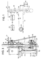
- FIG 1 illustrates, diagrammatically, an embodiment of the apparatus of the present invention.
- Figure 2 illustrates a cross-sectional perspective view of an embodiment of the apparatus of the present invention.
- Figure 3 illustrates a cross-sectional view of the apparatus illustrated in Figure 2 taken along lines III-III of Figure 2.
- Figure 4 illustrates a cross-sectional view of the apparatus of Figure 2 taken along lines IV-IV of Figure 2.
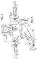
- Figure 5 illustrates a top elevational view of a portion of the apparatus of Figure 2.
- Figure 6 illustrates a perspective view of an embodiment of a fork, for retaining a port, of the present invention.
- a feature of the apparatus described is that, once the ports are placed in an initial position on the apparatus, either automatically or by an operator, the ports maintain their initial position relative to the apparatus until inserted through an aperture in the film.
- aperture refers to a hole or opening in a web of film that is created in the film so that the film can accept at least a portion of a port so that the port can be sealed to the film.
- form, fill, seal packaging machine means a machine for creating from a flexible web of film a bag for housing a product.
- the apparatus 10 includes a substantially T-shaped continuous chain loop 12.
- the chain structure 12 provides a plurality of forks 14; each fork 14 releasably retains a port 16.
- the ports 16 are positioned in the forks 14 and maintained on the chain 12 and delivered by the chain to a web of film 18.
- the first sprocket 20 is driven by a motor 25 and an indexer 26.
- the indexer 26 ensures that the first sprocket 20 is accurately rotated thereby accurately indexing the chain 12. As discussed in more detail below, this causes the ports 16 to be accurately aligned with an aperture in the web of film 18.
- the second sprocket 22 is coupled to the first sprocket 20 by a frame structure 34 and, as discussed in detail below, moves up and down with the first sprocket to position the port 16 and drive the chain 12.
- the third sprocket 24 functions as an idler sprocket and includes a brake to releasably prevent rotation of the third sprocket.
- the apparatus 10 functions not only to transport a port 16 from a storage location to a position where it can be inserted in an aperture in a web of film 18, but also functions to insert the port 16 in the aperture.
- a continuous chain loop 12 is utilized, it should be appreciated that other means for transporting the ports 16 can be utilized.
- the chain 12 is fed, around at least sprockets 20, 22, and 24; the sprockets cause the ports 16 to move in a similar direction to that of the flow of the web of film 18. Accordingly, in the embodiment illustrated, the sprockets 20, 22, and 24 rotate in a clockwise direction.
- the apparatus 10 includes a port positioning station 30 wherein a port 16 can be positioned within a fork 14.
- the forks 14 function to releasably retain the ports 16.
- the ports 16 can be positioned within the forks 14 at the port positioning station 30, either by an operator or automatically. Once so positioned, the ports 16 are transported by the chain 12 so that they can be positioned in an aperture in the web of film 18.
- Figure 6 illustrates an embodiment of a fork 14 that can be utilized in the present invention.
- the fork 14 insures that the port 16 is accurately positioned on the chain 12 and is delivered to an aperture in the web of film 18 while the integrity of its original position is maintained.
- the fork 14 allows the port 16 to be removed from the fork after it is received within the aperture of the web of film 18 due to the movement of the film.
- the fork 14 includes a body 71 that defines a channel 73.
- a slot-like aperture 75 is provided for allowing a base of the port 16 to be received within the channel 73.
- a biasing member 77 is provided for properly positioning the base, and thereby the port 16, with respect to the fork 14.
- the biasing member 77 is a tongue that extends for a length of the channel 73.
- the fork 14 provides a means for releasably retaining the port in juxtaposition to the chain.
- the biasing member 77 insures that the port 16 is properly positioned with respect to the fork 14.
- the fork 14, however, allows the port 16 to be easily removed therefrom due to the flow of film when the port is inserted into an aperture of the film.
- the chain structure 12, along with the forks 14 and ports 16, is driven by the first sprocket 20.
- the first sprocket 20 is driven by the motor 25 and indexer 26.
- the indexer 26 functions to accurately regulate the rotational movement of the first sprocket 20. As discussed in more detail, infra , this ensures that the chain 12 is properly indexed ensuring that the port 16 will be aligned with an aperture in the web of film 18.
- a Camco Indexer has been found to function satisfactorily as the indexer 26.
- a second sprocket 22 is provided that functions as an idler sprocket. Accordingly, the second sprocket 22 does not drive the chain 10 but rather functions to define, in part, the path of travel of the chain 12.
- the first sprocket 20 and second sprocket 22 are coupled together by a frame structure 34.
- the frame 34 couples the first sprocket 20 and second sprocket 22 so that they are substantially aligned in a position that is substantially perpendicular to a portion of the web of film 18.
- the frame 34 includes two fixed guide rods 36 and 38 to which each of the first sprocket 20 and second sprocket 22 are coupled.
- the first sprocket 20 and second sprocket 22 are coupled to the guide rods 36 and 38 so as to allow movement of the sprockets 20 and 22 with respect to the guide rods.
- the sprockets 20 and 22 are coupled to brackets 42 and 44, respectively.
- Each of the brackets 42 and 44 include bushings 46 and 48, respectively, allowing the brackets, and thereby the first and second sprockets 20 and 22, to move along the fixed guide rods 36 and 38.
- the brackets 42 and 44 are coupled together by a fixed rod 49.
- bracket 42 also includes a housing 50 upon which the indexer 26 and motor 25 are mounted. This allows the indexer 26 and motor 25 to move with the first sprocket 20.
- a piston 56 is provided.
- the piston 56 includes a cylinder 58 and piston rod 59.
- One end 61 of the cylinder rests on a plate 63 to which an end of each of the guide rods 36 and 38 is secured.
- the piston rod 59 is coupled to the housing 50. Therefore, upon movement of the piston 56, the fixed rod 40 and brackets 42, 44, and thereby the first and second sprockets 20 and 22 are moved along the guide rods 36 and 38.
- both the first and second sprockets 20 and 22 will move as a unit, either away from, or towards, a portion of the web of film 18. As set forth below in the discussion on the operation of the apparatus 10, this, in part, affords the apparatus 10 the ability to accurately position a port 16 with respect to an aperture in the web of film 18, allowing the first sprocket 20 to position the port within the aperture.
- a third sprocket 24 is provided.
- the third sprocket 24 includes a brake member 60 for releasably preventing the rotation of the third sprocket 24.
- sprockets or pinions 64, 66, 68, and 70 are provided.
- the sprockets 64, 66, 68, and 70 are also idler sprockets.
- the sprockets 64, 66, 68, and 70 allow the chain loop 12 to travel in a path that is not entirely parallel to the flow path of the film 18.
- the sprockets 64, 66, 68, and 70 allow the apparatus 10 to provide, in the embodiment illustrated, realignment clamp means 82.
- the realignment clamp means 82 insures that the port 16 is correctly positioned in a fork 14 at a top portion of the first sprocket 20 prior to the first sprocket 20 urging the port into an aperture in the web of film 18. It should be noted, however, that the realignment clamp means 82 may not be needed, depending on the fork structure utilized. In this regard, the inventors of the present invention believe that if the fork 14 illustrated in Figure 6 is utilized that the realignment clamp means 82 may not be necessary.
- the realignment clamp means 82 includes two clamp members 83 and 84 located on opposing sides of the first sprocket 20.
- the clamp members 83 and 84 include port alignment members 86 and 88, respectively.
- the realignment clamp means 82 can be actuated causing the port alignment members 86 and 88 to contact the port.
- the port alignment members 86 and 88 are so constructed and arranged that they center the port 16 within the fork 14. Accordingly, if, for some reason, the port 16 became misaligned within the fork 14, or was not properly positioned therein originally, the clamp means 82 will ensure that the port 16 is correctly positioned. To cause the port alignment members 86 and 88 to contact the port 16, piston members 90 and 92 are provided for actuating the clamp members 83 and 84.
- the apparatus 10 functions as follows.
- the phantom lines in Figure 2 illustrate the port 16 in a position where it will be taken away by the web of film 18 after it has been inserted within an aperture in the film.
- the brake 60 is actuated on the third sprocket 24.
- the indexer 26 and motor 25 cause the first sprocket 20 to rotate a predetermined rotational distance. This distance causes the chain 12 to be indexed, i.e., moved, a certain distance.
- the first sprocket 20 is indexed, i.e., rotated, by 120°. The distance the chain 12 is indexed and the first sprocket 20 is rotated, corresponds to one bag length of the web of film 18.
- the indexing, i.e., rotation, of the first sprocket 20 causes the frame 34, and thereby the first and second sprockets 20 and 22, respectively, to move downwardly as illustrated in the solid lines in Figure 2.
- the piston 56 can also be actuated causing the frame 34 to move downwardly. This results in the chain 14 being indexed and causing a port 16 to move into the uppermost position on the first sprocket 20 as illustrated in solid lines in Figure 2.
- the brake 60 is removed from the third sprocket 24. Fluid is then urged into the cylinder 58 of the piston causing the piston rod 59 to move upwardly urging the frame 34 and the first and second sprockets 20 and 22 to move toward at least a portion of the web of film 18. During this step of the process, the indexer 26 prevents the first sprocket 20 from rotating.
- the web of film 18 will also be fed through the packaging machine.
- the apparatus 10, and the process steps of same are coordinated with the flow of the web of film through the packaging machine. Therefore, during this later step, the web of film 18 will have been advanced so that the upward movement of the first sprocket 20 will cause the port 16 to be received in an aperture in the web of film.
- a port 16 can be placed in a fork 14 at the port positioning station 30. Because the third sprocket 24 cannot rotate, the chain 12 will not move at this time at the port positioning station 30 allowing an easy placement of the port 16 in the fork 14.
- the process steps are as follows: 1) activate the brake 60 on the third sprocket 24; 2) activate the indexer 26 and motor 25 to cause the first sprocket 20 to move a predetermined rotational distance causing the first and second sprockets 20 and 22 to move downwardly; 3) the first and second sprockets 20 and 22 move downwardly causing a port 16 to be indexed in an uppermost position on the first sprocket 20; 4) preventing rotation of the first sprocket 20; 5) deactivating the brake 60 on the third sprocket 24; and 6) activating the piston 56 to cause the first and second sprockets 20 and 22 to move upwardly causing a port 16 to be received within an aperture of the film 18.
- the apparatus 10 provides a direct feed of the port 16 to the web of film 18 so that the alignment of the port is maintained at all times. Because the system is in movement for a very short time, it is easy, if a manual positioning of the port is utilized, for an operator to position a port 16 within a fork 14. This is in contrast to previous apparatus in which the chain is in motion during most of the operation, and therefore, the window within which an operator has to position the port in the fork is very short. In contrast, the chain loop, at the port inserter station, only moves when the port is inserted in the film.
Landscapes
- Engineering & Computer Science (AREA)
- Mechanical Engineering (AREA)
- Auxiliary Devices For And Details Of Packaging Control (AREA)
- Replacement Of Web Rolls (AREA)
- Registering, Tensioning, Guiding Webs, And Rollers Therefor (AREA)
- Making Paper Articles (AREA)
- Containers And Plastic Fillers For Packaging (AREA)
- Advancing Webs (AREA)
Claims (12)
- Vorrichtung, um eine Verbindungseinrichtung (16) in einer Öffnung einer Folienbahn (18) zu positionieren, wobei die Vorrichtung folgendes aufweist:- ein Förderelement (12), um Verbindungseinrichtungen zu fördern, das eine Vielzahl von Halteeinrichtungen (14) aufweist, die entlang diesem im Abstand voneinander vorgesehen sind, um Verbindungseinrichtungen lösbar zu halten, wobei das Förderelement (12) um ein erstes und ein zweites drehbares Element (20, 22) herum verläuft, und- eine Schalteinrichtung (26), um das Förderelement um die drehbaren Elemente herum zu treiben, um die Verbindungseinrichtungen vorwärtszubewegen,dadurch gekennzeichnet,
daß die Schalteinrichtung (26) mit dem ersten drehbaren Element gekoppelt ist, um die Drehung des ersten drehbaren Elements (20) genau zu regulieren, daß das erste und das zweite drehbare Element (20, 22) miteinander gekoppelt sind,
und daß eine Positioniereinrichtung (34, 56, 60) vorgesehen ist, die betätigbar ist, um dafür zu sorgen, daß die drehbaren Elemente und ein Bereich des Förderelements (12) um das erste drehbare Element (20) herum sich in Übereinstimmung miteinander auf eine gegebene Ebene zu und von dieser weg in einer im wesentlichen senkrechten Richtung zu dieser Ebene zu bewegen, um eine Verbindungseinrichtung (16) in einer Öffnung in einem Bereich der Folienbahn (18) zu positionieren, der in dieser Ebene liegt. - Vorrichtung nach Anspruch 1,
wobei die Positioniereinrichtung (34, 56, 60) einen Kolben (36) aufweist, der mit dem ersten drehbaren Element (20) gekoppelt ist. - Vorrichtung nach Anspruch 1 oder 2,
wobei das erste (20) und das zweite drehbare Element (22) mit einem Rahmen (34) in einer im wesentlichen ausgefluchteten Beziehung zueinander gekoppelt sind und das dritte drehbare Element (24) in einer Position angeordnet ist, die von einer Ebene versetzt ist, die von dem ersten und dem zweiten drehbaren Element definiert ist. - Vorrichtung nach einem der vorhergehenden Ansprüche,
wobei das Förderelement eine durchgehende Kettenschleife (12) ist und die drehbaren Elemente (20, 22) Kettenräder sind. - Vorrichtung nach einem der vorhergehenden Ansprüche,
wobei das Förderelement (12) um ein drittes drehbares Element (24) herum verläuft und die Vorrichtung eine Einrichtung (60) aufweist, um das Drehen des dritten Element (24) zu verhindern, während die Schalteinrichtung (26) betätigt wird, so daß das erste und das zweite drehbare Element dazu veranlaßt werden, sich in Übereinstimmung miteinander von der gegebenen Ebene wegzubewegen. - Vorrichtung nach Anspruch 5,
die eine Verbindungseinrichtungs-Einsetzstation (30) aufweist, um das Einführen von Verbindungseinrichtungen (16) in die Halteeinrichtungen (14) zum lösbaren Halten der Verbindungseinrichtungen zuzulassen, wobei die Einführstation zwischen dem ersten (20) und dem dritten (24) drehbaren Element angeordnet ist. - Vorrichtung nach Anspruch 5 oder 6,
die eine Verbindungseinrichtungs-Wiederausfluchtungseinrichtung (82) aufweist, um die Verbindungseinrichtung in der Halteeinrichtung (14) genau zu positionieren, bevor sie in die Öffnung in der Folienbahn (18) eingesetzt wird. - Vorrichtung nach Anspruch 7,
die mindestens ein viertes drehbares Element (64, 66, 68, 70) aufweist, um eine Förderbahn für das Förderelement (12) zu bilden, die das Anordnen der Verbindungseinrichtungs-Wiederausfluchtungseinrichtung (82) in der Nähe des ersten drehbaren Elementes (20) ermöglicht. - Vorrichtung nach einem der vorhergehenden Ansprüche,
wobei jede Halteeinrichtung zum lösbaren Halten einer Verbindungseinrichtung eine Gabel (14) mit einem Körper (71) ist, der einen Kanal (73) bildet, um einen Bereich der Verbindungseinrichtung (16) aufzunehmen. - Vorrichtung nach Anspruch 9,
wobei der Kanal (73) eine Vorspanneinrichtung (77) aufweist, um den Bereich der Verbindungseinrichtung (16), der in dem Kanal aufgenommen ist, in Richtung zu einem oberen Bereich der Gabel vorzuspannen. - Vorrichtung nach Anspruch 10,
wobei die Vorspanneinrichtung (77) eine Zunge aufweist, die sich zumindest über einen wesentlichen Bereich der Länge des Kanals (73) erstreckt. - Verwendung der Vorrichtung nach Anspruch 5 in Abhängigkeit von Anspruch 2, die die folgenden Schritte aufweist:- Positionieren von Verbindungseinrichtungen in den Halteeinrichtungen (14),- Betätigen des Kolbens (36), um das erste und das zweite drehbare Element (20, 22), die miteinander gekoppelt sind, und einen Bereich des Förderelements (12) auf eine Folienbahn (18) zu zu bewegen, um eine Verbindungseinrichtung in eine Öffnung in der Bahn einzusetzen,- Vorwärtsbewegen der Folie, um die eingesetzte Verbindungseinrichtung von dem Förderelement (12) zu entfernen,- Betätigen der Schalteinrichtung (26), um das erste drehbare Element (20) zu drehen, um das Förderelement (12) vorwärtszubewegen, während gleichzeitig ein Drehen des dritten drehbaren Elements (24) verhindert wird, so daß das erste und das zweite drehbare Element (20, 22), die miteinander gekoppelt sind, und das Förderelement (12) dazu veranlaßt werden, sich von der Bahn wegzubewegen, und eine weitere Verbindungseinrichtung durch die Vorwärtsbewegung des Förderelements (12) in eine Position zum Einsetzen in die Bahn bewegt wird, und- Betätigen des Kolbens (36), um das erste und das zweite drehbare Element (22, 24), die miteinander gekoppelt sind, wieder auf die Bahn zuzubewegen, während gleichzeitig ein Drehen des ersten drehbaren Elements (20) verhindert und ein Drehen des dritten drehbaren Elements (24) zugelassen wird.
Applications Claiming Priority (2)
| Application Number | Priority Date | Filing Date | Title |
|---|---|---|---|
| US07/358,281 US5024645A (en) | 1989-05-26 | 1989-05-26 | Apparatus for positioning a port in an aperture in a web of film |
| US358281 | 1989-05-26 |
Publications (3)
| Publication Number | Publication Date |
|---|---|
| EP0428679A1 EP0428679A1 (de) | 1991-05-29 |
| EP0428679A4 EP0428679A4 (en) | 1992-07-08 |
| EP0428679B1 true EP0428679B1 (de) | 1994-02-23 |
Family
ID=23409035
Family Applications (1)
| Application Number | Title | Priority Date | Filing Date |
|---|---|---|---|
| EP90908757A Expired - Lifetime EP0428679B1 (de) | 1989-05-26 | 1990-05-21 | Apparat und verfahren zur befestigung eines mundstücks in eine öffnung in einem band oder einer dünnen schicht |
Country Status (7)
| Country | Link |
|---|---|
| US (1) | US5024645A (de) |
| EP (1) | EP0428679B1 (de) |
| JP (1) | JPH04500186A (de) |
| AU (1) | AU622806B2 (de) |
| CA (1) | CA2032492C (de) |
| DE (1) | DE69006825T2 (de) |
| WO (1) | WO1990014217A1 (de) |
Families Citing this family (8)
| Publication number | Priority date | Publication date | Assignee | Title |
|---|---|---|---|---|
| NL9401413A (nl) * | 1994-08-31 | 1996-04-01 | Food Processing Systems | Eindloze transporteur met een continu voortbewegend en een intermitterend voortbewegend transporteurpart. |
| US8353147B2 (en) * | 1998-07-17 | 2013-01-15 | Robert Beiser | Apparatus and method for manufacture of a top opening reclosable bag having a tape formed reclosable seal |
| US6726612B1 (en) * | 1998-07-17 | 2004-04-27 | Z-Patch, Inc. | Continuous supply of preformed reclosable fasteners |
| US20110235951A1 (en) * | 1998-07-17 | 2011-09-29 | Com-Pac International, Inc. | Reclosable bag with tear open feature |
| US6098369A (en) * | 1998-07-17 | 2000-08-08 | Bodolay; William A. | Apparatus for attaching a reclosable fastener to a flexible material |
| US10053255B2 (en) * | 2014-05-02 | 2018-08-21 | SN Maschinenbau GmbH | Fitment delivery system |
| EP3271252B1 (de) | 2015-03-18 | 2021-04-21 | Kellogg Company | Aufrechtstehender beutel mit flachem boden, vertikales form-, füll- und versiegelungssystem und verfahren zur verwendung davon |
| DE102020115036A1 (de) * | 2020-06-05 | 2021-12-09 | Syntegon Technology Gmbh | Schweißvorrichtung sowie Verfahren zum Schweißen eines Auslasselements an ein Verpackungsmaterial |
Family Cites Families (18)
| Publication number | Priority date | Publication date | Assignee | Title |
|---|---|---|---|---|
| CA836904A (en) * | 1970-03-17 | Stirling Sintering Company | Reciprocating conveyor | |
| CA478421A (en) * | 1951-11-13 | F. Bamford Charles | Feed tables | |
| US2543283A (en) * | 1949-01-15 | 1951-02-27 | Frank Louis | Screw and nut driving tool |
| US2859670A (en) * | 1953-11-17 | 1958-11-11 | Rawe Martin | Securing device for valve-bags in valvebag manufacturing machines |
| US3069303A (en) * | 1960-02-05 | 1962-12-18 | Scholle Chemical Corp | Process and apparatus for producing flexible containers |
| US3434908A (en) * | 1965-11-12 | 1969-03-25 | Summerhayes Holdings Ltd | Sealing head |
| US3553934A (en) * | 1967-12-08 | 1971-01-12 | Riegel Paper Corp | Packaging machine for forming and filling bags of different lengths and widths |
| US3497084A (en) * | 1968-02-28 | 1970-02-24 | Morgan Construction Co | Means for counting,bundling and weighing of elongated elements |
| US3821046A (en) * | 1969-09-26 | 1974-06-28 | Kraftco Corp | Method of making dispensers |
| US3783080A (en) * | 1971-12-01 | 1974-01-01 | L Goglio | Apparatus for securing valves on flexible bags and flat sheets convertible into bags |
| US3812572A (en) * | 1973-02-14 | 1974-05-28 | Gen Films Inc | Tube applicator |
| US4027577A (en) * | 1975-07-25 | 1977-06-07 | Cutter Laboratories, Inc. | Bag-making apparatus and process for making ported bags |
| US4246062A (en) * | 1979-03-26 | 1981-01-20 | Christine William C | Apparatus for attaching a fitment to a pouch |
| AU559751B2 (en) * | 1982-10-18 | 1987-03-19 | Unitika Ltd. | Filling bags with cap bodies |
| JPS60212403A (ja) * | 1984-04-06 | 1985-10-24 | Nippon Petrochem Co Ltd | 塩素化されたエチレン共重合体の製法 |
| DE3612196A1 (de) * | 1986-04-11 | 1987-10-22 | Bosch Gmbh Robert | Vorrichtung zum herstellen von beutelpackungen mit entnahmestutzen |
| US4779397A (en) * | 1987-03-09 | 1988-10-25 | Baxter Travenol Laboratories, Inc. | Apparatus and method for attaching a fitment to a web of film |
| EP0343237B1 (de) * | 1987-12-05 | 1992-06-17 | Renishaw plc | Taster-wechsel-vorrichtung |
-
1989
- 1989-05-26 US US07/358,281 patent/US5024645A/en not_active Expired - Fee Related
-
1990
- 1990-05-21 DE DE69006825T patent/DE69006825T2/de not_active Expired - Fee Related
- 1990-05-21 CA CA002032492A patent/CA2032492C/en not_active Expired - Fee Related
- 1990-05-21 WO PCT/US1990/002803 patent/WO1990014217A1/en not_active Ceased
- 1990-05-21 EP EP90908757A patent/EP0428679B1/de not_active Expired - Lifetime
- 1990-05-21 JP JP2508263A patent/JPH04500186A/ja active Pending
- 1990-05-21 AU AU56716/90A patent/AU622806B2/en not_active Ceased
Also Published As
| Publication number | Publication date |
|---|---|
| US5024645A (en) | 1991-06-18 |
| DE69006825D1 (de) | 1994-03-31 |
| CA2032492C (en) | 1996-05-07 |
| DE69006825T2 (de) | 1994-09-22 |
| AU622806B2 (en) | 1992-04-16 |
| AU5671690A (en) | 1990-12-18 |
| JPH04500186A (ja) | 1992-01-16 |
| EP0428679A4 (en) | 1992-07-08 |
| WO1990014217A1 (en) | 1990-11-29 |
| CA2032492A1 (en) | 1990-11-27 |
| EP0428679A1 (de) | 1991-05-29 |
Similar Documents
| Publication | Publication Date | Title |
|---|---|---|
| US6490846B2 (en) | Opening arrangement for zipper-type pouches for continuous motion pouching machinery | |
| KR100691299B1 (ko) | 밀착된 일련의 백 부재로부터의 백 안에 물품을 충진하는 방법 및 장치 | |
| US3599388A (en) | Method of and apparatus for forming and loading containers | |
| EP0304479B1 (de) | Vorrichtung zum befestigen von füll- oder entleerelementen auf fortlaufenden folienbahnen | |
| US5467581A (en) | Apparatus and process for positioning a fitment | |
| EP0297814A2 (de) | Filmführungssystem | |
| EP0107474A2 (de) | Verfahren und Apparat zur Herstellung von Sackförmigen Verpackungen | |
| EP0242567A1 (de) | Vorrichtung zum Füllen von Beuteln | |
| US5579894A (en) | Direct drop transfer apparatus | |
| US5024645A (en) | Apparatus for positioning a port in an aperture in a web of film | |
| EP1227041B1 (de) | Vorrichtung zum Anbringen eines Behälterverschlusses | |
| US4275977A (en) | Apparatus and method for individual bag working and stacking | |
| US5070680A (en) | Apparatus for opening a flat tube and fitting same on a container or the like | |
| JPH0375402B2 (de) | ||
| PL168095B1 (pl) | Urzadzenie do napelniania i zamykania opakowan ze srodkiem plynnym PL PL PL | |
| EP3601070B1 (de) | Beutelbahn und verfahren und ausrüstung zum verpacken von artikeln | |
| US3672265A (en) | Apparatus for stacking flattened bags of thermoplastic material which are made in a bag-making machine | |
| AU624957B2 (en) | Vertical dancer with constant torque | |
| EP1164081A1 (de) | Vorrichtung zum überführen von beuteln in automatischen verpackungsmaschinen | |
| CA1279784C (en) | Device for positioning fitments in a perforated film and perforated film equipped with parts or fittings | |
| JP3330646B2 (ja) | 袋を製造し、充填し、密封する方法 | |
| JPH02194940A (ja) | ヘッダー付袋の自動充填包装機 | |
| EP0965521A1 (de) | Vorrichtung zum Verpacken von Schüttgütern oder Gruppen von Gegenständen in einem Schlauchbeutel | |
| KR100315393B1 (ko) | 포장장치 | |
| WO2017169653A1 (ja) | ラベル被嵌システム |
Legal Events
| Date | Code | Title | Description |
|---|---|---|---|
| PUAI | Public reference made under article 153(3) epc to a published international application that has entered the european phase |
Free format text: ORIGINAL CODE: 0009012 |
|
| AK | Designated contracting states |
Kind code of ref document: A1 Designated state(s): BE DE FR GB |
|
| 17P | Request for examination filed |
Effective date: 19910104 |
|
| A4 | Supplementary search report drawn up and despatched |
Effective date: 19920514 |
|
| AK | Designated contracting states |
Kind code of ref document: A4 Designated state(s): BE DE FR GB |
|
| 17Q | First examination report despatched |
Effective date: 19930326 |
|
| GRAA | (expected) grant |
Free format text: ORIGINAL CODE: 0009210 |
|
| AK | Designated contracting states |
Kind code of ref document: B1 Designated state(s): BE DE FR GB |
|
| REF | Corresponds to: |
Ref document number: 69006825 Country of ref document: DE Date of ref document: 19940331 |
|
| ET | Fr: translation filed | ||
| PLBE | No opposition filed within time limit |
Free format text: ORIGINAL CODE: 0009261 |
|
| STAA | Information on the status of an ep patent application or granted ep patent |
Free format text: STATUS: NO OPPOSITION FILED WITHIN TIME LIMIT |
|
| 26N | No opposition filed | ||
| PGFP | Annual fee paid to national office [announced via postgrant information from national office to epo] |
Ref country code: FR Payment date: 19960321 Year of fee payment: 7 |
|
| PGFP | Annual fee paid to national office [announced via postgrant information from national office to epo] |
Ref country code: GB Payment date: 19960325 Year of fee payment: 7 |
|
| PGFP | Annual fee paid to national office [announced via postgrant information from national office to epo] |
Ref country code: BE Payment date: 19960425 Year of fee payment: 7 |
|
| PGFP | Annual fee paid to national office [announced via postgrant information from national office to epo] |
Ref country code: DE Payment date: 19960628 Year of fee payment: 7 |
|
| PG25 | Lapsed in a contracting state [announced via postgrant information from national office to epo] |
Ref country code: GB Effective date: 19970521 |
|
| PG25 | Lapsed in a contracting state [announced via postgrant information from national office to epo] |
Ref country code: BE Effective date: 19970531 |
|
| BERE | Be: lapsed |
Owner name: BAXTER INTERNATIONAL INC. Effective date: 19970531 |
|
| GBPC | Gb: european patent ceased through non-payment of renewal fee |
Effective date: 19970521 |
|
| PG25 | Lapsed in a contracting state [announced via postgrant information from national office to epo] |
Ref country code: FR Free format text: LAPSE BECAUSE OF NON-PAYMENT OF DUE FEES Effective date: 19980130 |
|
| PG25 | Lapsed in a contracting state [announced via postgrant information from national office to epo] |
Ref country code: DE Free format text: LAPSE BECAUSE OF NON-PAYMENT OF DUE FEES Effective date: 19980203 |
|
| REG | Reference to a national code |
Ref country code: FR Ref legal event code: ST |