EP0965521A1 - Vorrichtung zum Verpacken von Schüttgütern oder Gruppen von Gegenständen in einem Schlauchbeutel - Google Patents
Vorrichtung zum Verpacken von Schüttgütern oder Gruppen von Gegenständen in einem Schlauchbeutel Download PDFInfo
- Publication number
- EP0965521A1 EP0965521A1 EP98111024A EP98111024A EP0965521A1 EP 0965521 A1 EP0965521 A1 EP 0965521A1 EP 98111024 A EP98111024 A EP 98111024A EP 98111024 A EP98111024 A EP 98111024A EP 0965521 A1 EP0965521 A1 EP 0965521A1
- Authority
- EP
- European Patent Office
- Prior art keywords
- sleeve
- articles
- feeding
- machine
- continuous sheet
- Prior art date
- Legal status (The legal status is an assumption and is not a legal conclusion. Google has not performed a legal analysis and makes no representation as to the accuracy of the status listed.)
- Withdrawn
Links
- 238000004806 packaging method and process Methods 0.000 title claims abstract description 7
- 238000003466 welding Methods 0.000 claims description 13
- 238000005520 cutting process Methods 0.000 claims description 6
- 238000007493 shaping process Methods 0.000 claims description 2
- 230000015572 biosynthetic process Effects 0.000 claims 1
- 230000005484 gravity Effects 0.000 description 3
- 238000004519 manufacturing process Methods 0.000 description 2
- 238000000034 method Methods 0.000 description 2
- 238000006073 displacement reaction Methods 0.000 description 1
- 230000007420 reactivation Effects 0.000 description 1
- 238000007789 sealing Methods 0.000 description 1
- 238000011144 upstream manufacturing Methods 0.000 description 1
Images


Classifications
-
- B—PERFORMING OPERATIONS; TRANSPORTING
- B65—CONVEYING; PACKING; STORING; HANDLING THIN OR FILAMENTARY MATERIAL
- B65B—MACHINES, APPARATUS OR DEVICES FOR, OR METHODS OF, PACKAGING ARTICLES OR MATERIALS; UNPACKING
- B65B35/00—Supplying, feeding, arranging or orientating articles to be packaged
- B65B35/30—Arranging and feeding articles in groups
- B65B35/40—Arranging and feeding articles in groups by reciprocating or oscillatory pushers
-
- B—PERFORMING OPERATIONS; TRANSPORTING
- B65—CONVEYING; PACKING; STORING; HANDLING THIN OR FILAMENTARY MATERIAL
- B65B—MACHINES, APPARATUS OR DEVICES FOR, OR METHODS OF, PACKAGING ARTICLES OR MATERIALS; UNPACKING
- B65B9/00—Enclosing successive articles, or quantities of material, e.g. liquids or semiliquids, in flat, folded, or tubular webs of flexible sheet material; Subdividing filled flexible tubes to form packages
- B65B9/10—Enclosing successive articles, or quantities of material, in preformed tubular webs, or in webs formed into tubes around filling nozzles, e.g. extruded tubular webs
- B65B9/20—Enclosing successive articles, or quantities of material, in preformed tubular webs, or in webs formed into tubes around filling nozzles, e.g. extruded tubular webs the webs being formed into tubes in situ around the filling nozzles
- B65B9/213—Enclosing successive articles, or quantities of material, in preformed tubular webs, or in webs formed into tubes around filling nozzles, e.g. extruded tubular webs the webs being formed into tubes in situ around the filling nozzles the web having intermittent motion
-
- B—PERFORMING OPERATIONS; TRANSPORTING
- B65—CONVEYING; PACKING; STORING; HANDLING THIN OR FILAMENTARY MATERIAL
- B65B—MACHINES, APPARATUS OR DEVICES FOR, OR METHODS OF, PACKAGING ARTICLES OR MATERIALS; UNPACKING
- B65B9/00—Enclosing successive articles, or quantities of material, e.g. liquids or semiliquids, in flat, folded, or tubular webs of flexible sheet material; Subdividing filled flexible tubes to form packages
- B65B9/06—Enclosing successive articles, or quantities of material, in a longitudinally-folded web, or in a web folded into a tube about the articles or quantities of material placed upon it
- B65B2009/063—Forming shoulders
Definitions
- the present invention relates to a machine for packaging bulk articles or groups of articles in a tubular envelope or bag.
- Packs containing more articles previously wrapped one by one are also known as multi-packs.
- these machines for obtaining the tube from a sheet of heat sealable material include:
- the product or articles are fragile, they can be damaged on the way to the bottom of the tube, due to striking or rubbing against the sleeve inner surface or against each other.
- the sleeve inner shape exactly matches the articles outer shape, the latter can jam while falling along the sleeve because they tend to assume inclined positions thus increasing rubbing against the inner surfaces.
- the object of the present invention is to propose a machine for packaging a bulk product or groups of articles inside a tubular pack or bag like the one just described, the machine being improved so as to overwhelm the disadvantages.
- the proposed machine must be capable of packaging the bulk product or the articles, in a tubular pack or bag at the same time when the tube is being formed, without damaging the articles and/or changing their arrangement.
- Another object of the invention id to propose a machine like the one of the prior art, improved in a way that no risk of jams inside the sleeve can occur.
- Another object of the present invention is to propose a machine improved by a simple and effective technical solution, which is reliable and does not involve high production costs.
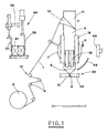
- the machine for packaging bulk product or groups of articles in a pack or bag includes means 10 for feeding the continuous sheet material 1 while placing it around a sleeve 11 to form an elongate tube 4, as in the know methods.
- Welding means 15 seal the longitudinal edges of the continuous sheet 1, in overlapped or facing-each-other condition, for forming the tube.
- the feeding means 10, which supply the continuous sheet material 1, include a reel 2, from which the continuous sheet 1 is unwound, and a series of turnabout rollers 6.
- the turnabout rollers 6 form a compensation mechanism, that compensate for slight differences between the quantity of the continuous sheet material unwound from the reel 2 and the quantity of the continuous sheet material actually used for forming the bags or packs.
- the welding means include a heat welder of known type, which seals the longitudinal edges of the continuous sheet material in overlapped or folded and facing-each-other condition.
- the tube portion longitudinally sealed and situated around the sleeve will be hereinafter referred to as the envelope 3.
- the continuous sheet material 1 is pulled by suitable means 18 including one or more motor powered endless belts, which press the continuous sheet 1 against the sleeve 11 for making it advance in direction A ( Figure 1).
- the figures show only one pair of endless belts 18, but obviously more pairs of endless belts can be provided, arranged along the sleeve circumference to increase the pulling action.
- Cutting and welding means 30, situated at the bottom of the sleeve 11, include two heated plates 31, 32, which simultaneously seal and sever crosswise the tube 4, to seal and separate single packs or bags 5.
- the sleeve 11, the collar 12, the welder 15 and the pulling endless belts 18 are mounted on an oscillating frame 7, which can rotate about a horizontal axis.
- Driving means not shown, since they are of known type, drive the frame to rotate about this horizontal axis, so that the sleeve 11 assumes, in alternative steps, a horizontal condition H and a vertical condition V, for the purpose which will be explained later.
- the feeding means 40 for feeding the product or the articles being packed are situated beside the frame 7, that supports the sleeve 11 and the collar 12.
- the means 40 for feeding articles are aimed at introducing the product or articles 41 into the sleeve 11, bringing them up to the bottom of the envelope when the sleeve is in its horizontal condition H.
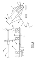
- the means 40 for feeding articles include a plate 44 situated near a sliding surface 43 and reciprocated horizontally, so as to enter the sleeve 11 when the sleeve is in its horizontal condition H.
- these articles feeding means include a pusher 42, also reciprocated horizontally, so as to enter the sleeve 11 kept horizontal.
- the bulk product, or a number of articles 41, are accumulated orderly on the sliding surface 43 by manipulators equipped with dragging plates 37, 38 and operated by actuators 39 of known type.
- the subject machine includes also folding means 45 which act on the bottom of the envelope 3 during rotation of the sleeve, so as to fold, in two steps, the edges welded in the region of the bottom.
- the folding means include substantially a curved member 45, situated at the side of the frame 7 opposite to the articles feeding means 40, and in the intermediate position of the path followed by the bottom of the envelope 3.
- the curve centre of the curved member 45 is aligned with the rotation axis of the oscillating frame 7.
- a pad 46 situated on the side of the sleeve opposite to the one having the articles feeding means 40 and at the bottom of the sleeve 11 in horizontal condition H.
- the pad 46 is reciprocated horizontally by driving means, not shown, insofar as they are known.
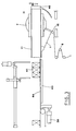
- the welding and cutting plates 31,32 are operated by moving them close to each other until they clamp, seal and sever the tube 4, separating therefrom the previously completed pack or bag 5 ( Figure 8).
- the frame 7 is rotated, e.g. in counter-clockwise direction N.
- the curved member 45 which is narrower than the tube 4, strikes against the central part of the welded bottom 8, considered in crosswise direction, folding it in the direction opposite to the rotation and folding it toward the centre of the two outer wings 9 of the welded bottom ( Figure 2).
- the manipulators 37 and the dragging plates 38 place orderly the articles 41, that have been separately wrapped along the wrapping line 35 situated upstream of the subject machine.
- the sleeve 11 When the rotation of the frame 7 is completed, the sleeve 11 is in horizontal condition H and its inlet opening is situated near the edge of the sliding surface 43.
- the plate 44 is operated, and enters the sleeve due to the action of a linear actuator 36. Motion of the plate 44 in the introduction direction T moves the articles up to the bottom of the tube ( Figures 3 and 4).
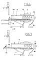
- the pad 46 is moved in push direction S, so as to press the wings 9 of the welded bottom 8, making it assume a flat shape.
- the frame 7 is rotated, e.g. in direction F, to bring the sleeve 11 back to its vertical condition V ( Figure 6).
- the curved member 45 hits the wings 9 of the envelope 3 to stabilise their folding.
- Figure 9 shows another embodiment of the means 40 for feeding the articles, which include the pusher 42. Machine operation is not different from the previous one.
- the raising device 34 is missing, as the pusher return movement does not act in any way on the articles 41, which remain at the bottom of the sleeve 11.
- This embodiment is more suitable when horizontally layered articles are to be packed, since the horizontal displacement of the articles one with respect to another could create problems if the previously described embodiment were used.
- the subject machine packages bulk product or groups of articles inside a tubular pack or bag of the type described in the introductory statement, without damaging the articles integrity and their arrangement, and without risking jams of singularly packaged articles inside the sleeve.
- the plate 44 and the pusher 42 move the articles always positively, thus avoiding jams possibility.
Landscapes
- Engineering & Computer Science (AREA)
- Mechanical Engineering (AREA)
- Containers And Plastic Fillers For Packaging (AREA)
Priority Applications (1)
| Application Number | Priority Date | Filing Date | Title |
|---|---|---|---|
| EP98111024A EP0965521A1 (de) | 1998-06-16 | 1998-06-16 | Vorrichtung zum Verpacken von Schüttgütern oder Gruppen von Gegenständen in einem Schlauchbeutel |
Applications Claiming Priority (1)
| Application Number | Priority Date | Filing Date | Title |
|---|---|---|---|
| EP98111024A EP0965521A1 (de) | 1998-06-16 | 1998-06-16 | Vorrichtung zum Verpacken von Schüttgütern oder Gruppen von Gegenständen in einem Schlauchbeutel |
Publications (1)
| Publication Number | Publication Date |
|---|---|
| EP0965521A1 true EP0965521A1 (de) | 1999-12-22 |
Family
ID=8232132
Family Applications (1)
| Application Number | Title | Priority Date | Filing Date |
|---|---|---|---|
| EP98111024A Withdrawn EP0965521A1 (de) | 1998-06-16 | 1998-06-16 | Vorrichtung zum Verpacken von Schüttgütern oder Gruppen von Gegenständen in einem Schlauchbeutel |
Country Status (1)
| Country | Link |
|---|---|
| EP (1) | EP0965521A1 (de) |
Cited By (6)
| Publication number | Priority date | Publication date | Assignee | Title |
|---|---|---|---|---|
| WO2001049566A1 (de) * | 2000-01-07 | 2001-07-12 | Festo Gesellschaft Mbh | Anlage zur vollautomatischen herstellung einer geschlossenen, durch eine folie gebildeten umhüllung um ein gut |
| EP1095856A3 (de) * | 1999-10-27 | 2001-10-10 | P.F.M. S.p.A. | Horizontale Verpackungsmaschine für Mehrfachpackungen |
| WO2007135088A1 (en) * | 2006-05-18 | 2007-11-29 | Alessandra Sambugaro | Packaging machine using heat sealable film |
| DE102011102245A1 (de) * | 2011-05-20 | 2012-11-22 | Hastamat Verpackungstechnik Gmbh | Vorrichtung und Verfahren zum Verpacken von stückigen Produkten |
| US9859051B2 (en) | 2012-06-11 | 2018-01-02 | Powerbyproxi Limited | Magnetically permeable core for use in wireless power transfer systems |
| US11043841B2 (en) | 2016-05-25 | 2021-06-22 | Apple Inc. | Coil arrangement |
Citations (4)
| Publication number | Priority date | Publication date | Assignee | Title |
|---|---|---|---|---|
| DE1915044U (de) * | 1964-09-30 | 1965-04-29 | Heinz E Mueller | Vorrichtung zur herstellung von schlauchaehnlichen packungen. |
| DE1929956U (de) * | 1964-04-08 | 1965-12-23 | Hoefliger & Karg | Schlauchbeutelform-, -fuell- und -schliessmaschine. |
| FR2600052A1 (fr) * | 1986-06-13 | 1987-12-18 | Fuji Machinery Co | Appareil de transport de bande intermittent |
| EP0573811A1 (de) * | 1992-06-06 | 1993-12-15 | Rovema Verpackungsmaschinen GmbH | Schlauchbeutelmaschine zur kontinuierlichen Herstellung von mit Seitenfalten versehenen Beuteln |
-
1998
- 1998-06-16 EP EP98111024A patent/EP0965521A1/de not_active Withdrawn
Patent Citations (4)
| Publication number | Priority date | Publication date | Assignee | Title |
|---|---|---|---|---|
| DE1929956U (de) * | 1964-04-08 | 1965-12-23 | Hoefliger & Karg | Schlauchbeutelform-, -fuell- und -schliessmaschine. |
| DE1915044U (de) * | 1964-09-30 | 1965-04-29 | Heinz E Mueller | Vorrichtung zur herstellung von schlauchaehnlichen packungen. |
| FR2600052A1 (fr) * | 1986-06-13 | 1987-12-18 | Fuji Machinery Co | Appareil de transport de bande intermittent |
| EP0573811A1 (de) * | 1992-06-06 | 1993-12-15 | Rovema Verpackungsmaschinen GmbH | Schlauchbeutelmaschine zur kontinuierlichen Herstellung von mit Seitenfalten versehenen Beuteln |
Cited By (9)
| Publication number | Priority date | Publication date | Assignee | Title |
|---|---|---|---|---|
| EP1095856A3 (de) * | 1999-10-27 | 2001-10-10 | P.F.M. S.p.A. | Horizontale Verpackungsmaschine für Mehrfachpackungen |
| WO2001049566A1 (de) * | 2000-01-07 | 2001-07-12 | Festo Gesellschaft Mbh | Anlage zur vollautomatischen herstellung einer geschlossenen, durch eine folie gebildeten umhüllung um ein gut |
| WO2007135088A1 (en) * | 2006-05-18 | 2007-11-29 | Alessandra Sambugaro | Packaging machine using heat sealable film |
| RU2391266C1 (ru) * | 2006-05-18 | 2010-06-10 | Алессандра САМБУГАРО | Упаковочная машина, в которой используется термосвариваемая пленка |
| US8375689B2 (en) | 2006-05-18 | 2013-02-19 | Lorapack S.R.L. | Packaging machine using heat sealable film |
| DE102011102245A1 (de) * | 2011-05-20 | 2012-11-22 | Hastamat Verpackungstechnik Gmbh | Vorrichtung und Verfahren zum Verpacken von stückigen Produkten |
| DE102011102245B4 (de) * | 2011-05-20 | 2014-07-17 | Hastamat Verpackungstechnik Gmbh | Vorrichtung und Verfahren zum Verpacken von stückigen Produkten |
| US9859051B2 (en) | 2012-06-11 | 2018-01-02 | Powerbyproxi Limited | Magnetically permeable core for use in wireless power transfer systems |
| US11043841B2 (en) | 2016-05-25 | 2021-06-22 | Apple Inc. | Coil arrangement |
Similar Documents
| Publication | Publication Date | Title |
|---|---|---|
| US3983682A (en) | Apparatus for forming, filling and inserting filled bags into cartons | |
| US4563862A (en) | Package forming apparatus with combined holding and stripper mechanism | |
| US3956866A (en) | Packaging method and apparatus | |
| US3513629A (en) | Overwrap packing machines | |
| US4918906A (en) | Method and apparatus for producing a bag-in-carton | |
| EP0453522A4 (en) | Form, fill, seal and separate packaging machine for reclosable containers | |
| JPS60158009A (ja) | 製袋充填機 | |
| CN87104442A (zh) | 在用薄片材料制成的包装里包装各种产品的方法和使用该方法的设备和因而得到的包装 | |
| US20200062429A1 (en) | Apparatus and method for filling bulk materials into open bags | |
| US5269122A (en) | Apparatus and method for forming protective packages | |
| US5564252A (en) | Dual web intermittent motion packaging machine | |
| US4815253A (en) | Forming, filling and sealing bags and depositing them in cartons | |
| EP0965521A1 (de) | Vorrichtung zum Verpacken von Schüttgütern oder Gruppen von Gegenständen in einem Schlauchbeutel | |
| US3861121A (en) | Article packaging apparatus | |
| US20210188469A1 (en) | Device and method for packaging bulk materials in open bags | |
| EP0493332A1 (de) | Automatische Maschine zur Herstellung, zum Befüllen und zum Versiegeln von Kunststoff-Seitenfaltenbeuteln, insbesondere für das Verpacken von inerten Materialien | |
| US4974396A (en) | Apparatus for manufacturing bags | |
| US3722174A (en) | Packaging of liquid-filled flexible pouches in thermoplastic bags | |
| GB2061219A (en) | Apparatus for forming, filling, sealing and cartoning bags | |
| EP0532785B1 (de) | Einwickel- und Einschachtelmaschine, vorzugsweise für Garnspulen oder dergleichen | |
| JP5166998B2 (ja) | 縦形製袋充填包装機 | |
| JP2002347705A (ja) | ピロー包装機 | |
| JP4300039B2 (ja) | 製袋充填包装装置 | |
| JP7542453B2 (ja) | 縦形製袋充填包装機 | |
| US3065839A (en) | Container filling and closing machine conveyor |
Legal Events
| Date | Code | Title | Description |
|---|---|---|---|
| PUAI | Public reference made under article 153(3) epc to a published international application that has entered the european phase |
Free format text: ORIGINAL CODE: 0009012 |
|
| AK | Designated contracting states |
Kind code of ref document: A1 Designated state(s): AT BE CH CY DE DK ES FI FR GB GR IE IT LI LU MC NL PT SE |
|
| AX | Request for extension of the european patent |
Free format text: AL;LT;LV;MK;RO;SI |
|
| AKX | Designation fees paid | ||
| REG | Reference to a national code |
Ref country code: DE Ref legal event code: 8566 |
|
| STAA | Information on the status of an ep patent application or granted ep patent |
Free format text: STATUS: THE APPLICATION IS DEEMED TO BE WITHDRAWN |
|
| 18D | Application deemed to be withdrawn |
Effective date: 20000624 |