EP0425747B1 - Anzeigevorrichtung mit einer Farbbildröhre - Google Patents
Anzeigevorrichtung mit einer Farbbildröhre Download PDFInfo
- Publication number
- EP0425747B1 EP0425747B1 EP89403010A EP89403010A EP0425747B1 EP 0425747 B1 EP0425747 B1 EP 0425747B1 EP 89403010 A EP89403010 A EP 89403010A EP 89403010 A EP89403010 A EP 89403010A EP 0425747 B1 EP0425747 B1 EP 0425747B1
- Authority
- EP
- European Patent Office
- Prior art keywords
- field
- horizontal
- spaces
- deflection
- tabs
- Prior art date
- Legal status (The legal status is an assumption and is not a legal conclusion. Google has not performed a legal analysis and makes no representation as to the accuracy of the status listed.)
- Expired - Lifetime
Links
Images

Classifications
-
- H—ELECTRICITY
- H01—ELECTRIC ELEMENTS
- H01J—ELECTRIC DISCHARGE TUBES OR DISCHARGE LAMPS
- H01J29/00—Details of cathode-ray tubes or of electron-beam tubes of the types covered by group H01J31/00
- H01J29/46—Arrangements of electrodes and associated parts for generating or controlling the ray or beam, e.g. electron-optical arrangement
- H01J29/70—Arrangements for deflecting ray or beam
- H01J29/72—Arrangements for deflecting ray or beam along one straight line or along two perpendicular straight lines
- H01J29/76—Deflecting by magnetic fields only
- H01J29/762—Deflecting by magnetic fields only using saddle coils or printed windings
Definitions
- the invention relates to a self-converging color picture tube (CRT) display device.
- the electrons of each of the three electron beams of the CRT, R, G and B will traverse a greater distance when deflected towards the edge of the viewing screen than when directed toward the center. Due to the separation of the electron guns, this may result in a separation of the landing points of the three electron beams when they are deflected towards the edges of the screen. In uniform magnetic deflection fields, these effects combine to cause the light spots of the three beams at points on the viewing screen away from the center to be separated. This is known as misconvergence and results in color fringes about the edges of the displayed images. A certain amount of misconvergence is tolerable, but complete separation of the three illuminated spots is generally not acceptable. Misconvergence may be measured as a separation of the ideally superimposed red and blue lines of a crosshatch pattern of lines appearing on the screen when an appropriate test signal is applied to the picture tube.
- Each of the three electron beams scans a raster, which may be identified by its color.
- a green raster is ordinarily scanned by the center electron beam, and the outside beams scan red and blue rasters, respectively.
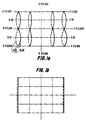
- the crosshatch pattern is formed in each of the red, green and blue rasters.
- the crosshatch pattern outlines the raster with generally vertical and horizontal lines, and also includes other intermediate vertically and horizontally-directed lines.
- the field intensity or flux lines produced by the horizontal deflection winding are made generally pincushion-shaped at a portion of the yoke that is closer to the screen than to the gun. Consequently at a given deflection current, the magnetic field is stronger at, for example, the right-center edge of the screen, referred to as the 3 o'clock hour point than at the center of the screen.
- Such field nonuniformity is known to reduce misconvergence at the 3 o'clock hour point, of a given vertical line.
- the field flux lines produced by the vertical deflection winding are made barrel-shaped at a portion of the yoke that is intermediate the gun end and the screen end of the yoke.
- Such field nonuniformity reduces misconvergence at the 12 o'clock point of a vertical line.
- the combination of the barrel-shaped and pincushion-shaped horizontal magnetic field reduces misconvergence at, for example, the right-top edge of the screen referred to as the 2 o'clock hour point.
- Such unacceptable misconvergence error may occur even though the misconvergence errors at both the 2 o'clock and the 3 o'clock hour points are acceptable.
- unacceptable misconvergence errors may occur at other vertical half-hour points on the respective intermediate vertical lines referred to as the 3:30, 8:30 and the 9:30 hour points. It may be desirable to reduce such unacceptable hourglass shaped misconvergence error at the half hour points such as, for example, at the 2:30 hour point on the vertical line without causing misconvergence at the 2 o'clock and at the 3 o'clock hour points on the vertical line.
- tabs or shunts having high permeability are placed on the horizontal deflection winding between the horizontal deflection winding and the neck of the CRT.
- the tabs are made of a mixture of a plastic material and a ferrite and are referred to by the name "plasto-ferrite".
- Such tabs are placed in an intermediate region on the horizontal deflection winding between an entrance region and an exit region of the yoke.
- Such tabs. are used for varying the fifth harmonic distribution of the horizontal magnetic field, obtained in accordance with the Fourier harmonic decomposition analysis, to reduce the aforementioned misconvergence errors at the half hour points.
- An alternative aspect of the invention is the use of spaces in the winding to achieve the desired fifth harmonic distribution.
- a self converged color display device includes a cathode ray tube having an evacuated glass envelope and including an array of different color representative phosphor elements disposed at one end of the envelope forming a display screen and an electron gun assembly disposed at a second end of the envelope.
- the electron gun assembly arranged to produce three horizontal in-line electron beams for energizing respective ones of the different color phosphor elements.
- a magnetically permeable core is included.
- Horizontal and vertical deflection coils are disposed in operating relationship relative to the core for producing -when energized horizontal and vertical deflection fields for causing the beams to scan a raster on the display screen.
- the horizontal deflection field has a predominately pincushion-shaped field for establishing beam convergence along a horizontal axis at vertical center of the display screen.
- the harmonic composition of the horizontal deflection field is modified to cause the horizontal deflection field to exhibit a fifth harmonic component that has a significant positive value for correcting a misconvergence error at a half hour point of the raster.
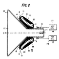
- FIG. 2 illustrates a longitudinal sectional view in diagrammatic form through a color television display tube assembly whose longitudinal axis is indicated by Z.
- a display tube, CRT 110 has a display screen 22, at the conical end of the tube.
- CRT 110 is, for example, of the type 66MP (medium planar) that is produced by Videocolor, Anagni, Italy, having a deflection angle 110° and a 66cm or 26V viewable screen size.
- the term MP indicates a radius of curvature, R>1, such as 1.5R.
- a neck end 33, remote from display screen 22 contains three in-line electron guns 44 situated in one plane; the longitudinal axis lying on that plane with the central electron gun centered on the axis.
- a deflection yoke 55 is mounted on CRT 110 such that is surrounds a portion of the neck and a portion of the conical or flared part.
- Deflection yoke 55 includes a line deflection coil assembly 77 formed by a pair of saddle coils 10. It includes a field deflection coil assembly 88 formed by a pair of toroidal coils 990 wound on a soft magnetic core 66.
- the two deflection coil assemblies are generally mounted on a support, not shown, of insulating material whose shape is substantially that of a frustum. Coils 10 are driven by a horizontal deflection circuit 177 and coils 990 are driven by a vertical deflection circuit 178 of a television receiver.
- Each saddle coil 10 has a straight, rear end turn portion 9 adjacent electron gun 44, referred to as the gun end. This end turn portion is not bent away from the neck of CRT 110, but lies generally parallel to longitudinal axis Z.
- a second, front end turn portion 19 of saddle coil 10 is located adjacent display screen 22, referred to as the screen end, and is bent away from axis Z in a direction generally transverse thereto.
- each of core 66 and the insulating support may be formed, advantageously, as a single piece, rather than being assembled from two pieces clipped or bonded together.
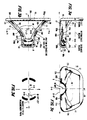
- Figures 3a, 3b and 3c illustrate side, top and rear views, respectively, of one of the pairs of saddle coil 10, embodying an aspect of the invention, of Figure 2. Each winding turn is formed by a wire conductor loop of generally saddle shape.
- the front end turns 19 of saddle coil 10 of Figures 3a-3c is joined to the straight rear end turns 9 by flared side members 11 and 12.
- the sections of side members 11 and 12 located in the exit region of the magnetic deflection field of yoke 55 are wound in a well known manner to provide front spaces 20 in the coil.
- Front spaces 20 affect or modify the harmonics of the current distribution in a manner to correct, for example, raster pattern or geometry distortions such as north-south distortion.
- the sections of side members 11 and 12, located in the entrance region of yoke 55 are wound in a well known manner to provide rear spaces 30 and 30a in the coil. Spaces 30 and 30a modify the harmonics of the current distribution in a manner to correct horizontal coma error.
- End turns 9 and 19 and side members 11 and 12 define a window 18.
- Coma errors are corrected in the entrance region of coil 10 region. Convergence errors are corrected in intermediate regions, between the exit and entrance regions. Geometry errors at the extreme edges of the display screen are corrected in the exit region.
- spaces 100 affect convergence. However, the effect of spaces 100 on horizontal coma is weaker than that of spaces 30 and 30a located in the entrance region. Similarly, the effect of spaces 100 on side pincushion raster distortion is weaker than that of spaces 20.
- Spaces 20, 30, and 30a are located in the end turn regions of saddle coil 10.
- the wire conductor that define the boundary of such a space is significantly curved for turning a corner to begin or complete an end turn portion of full winding turn. That is to say, each one of spaces 20, 30 and 30a is delineated in part by wires such as wire 98 of Figure 3A.
- a length of wire conductor 98 includes segments 98a and 98b that are oriented at a sharp angle to each other.
- a length of conductor wire 99 includes a segment 99c which forms one side of space 100, and includes wire segments 99a and 99c on either side of space 100 which are generally oriented in the same direction of the continuous winding before and after the winding space.
- wire segments 99a, 99b and 99c are disposed in the intermediate section of, for example, side member 12 of Figure 3b.
- Wire or conductor segments 99d, 99c, 99e and 99g, located at the four corners of coil 10, are sharply curved in order to form the loop-shape of a full winding turn.
- Spaces 100 are not associated with these wire segments 99d-99g. Therefore, by providing the capability of placing spaces 100 away from the corners of the coil, great flexibility exists in modifying the winding harmonic content to correct electron beam landing errors. For example, as explained later on, spaces 100 act to reduce the misconvergence at a half hour point such as at, for example, the 2:30 hour point on the vertical line of Figure 1a.
- a saddle coil as described above can be wound from copper wire of small dimension, the wire being coated with an electrical insulant and a thermo-setting adhesive.
- Winding takes place in a winding machine which winds the saddle coil substantially to its final shape and which introduces spaces 20, 30, 30a and 100 of Figures 3a-3c during the winding process. The shapes and locations of these spaces are determined by retractable pins in the winding head which limits the shapes these spaces can take.
- each saddle coil is retained in a jig with pressure being applied to obtain the required mechanical dimensions.
- a current is passed through the wire to soften the thermo-setting adhesive, which is afterwards allowed to cool to bond the wires together and form a self supporting saddle coil.
- the coefficients H 0 (Z), H 2 (Z) and H 4 (Z) can then be computed for different values of the coordinate Z.
- a graph can then be plotted depicting the variation of each of coefficients H 0 (Z), H 2 (Z) and H 4 (Z) as a function of the coordinate Z.
- Field distribution function H 2 is determined mainly by the third harmonic of the winding or current distribution in the saddle coil as a function of an angle ⁇ of Figure 3d.
- the magnitude of the third harmonic is computed using the Fourier analysis technique.
- parameter H 4 is determined mainly by the fifth harmonic.
- parameter H 4 and the fifth harmonic of the winding distribution of the coil have the same polarity.
- a deflection yoke designed similar to that of Figures 2 and 3a-3c but without spaces 100 of Figures 3a-3c, is used for performing the aforementioned magnetic field strength measurements.
- Such a yoke is referred to herein as the initially designed deflection yoke.
- the initially designed deflection yoke is otherwise, self converged and generally geometry corrected, except that it exhibits the half hour point misconvergence shown in Figure 1a.
- four field formers such as, for example, plasto-ferrite shunts or tabs 100', a pair of which being shown in broken line in Figure 3e, each having a dimension of, for example, 5mm x 10 mm, are placed symmetrically to axes X and Y.
- Four tabs 100' are placed on the side of saddle coil 10 that faces the glass envelope of CRT 100.
- a tab is placed in each of the four quadrants at a corresponding one of four predetermined angles ⁇ , 180° ⁇ of Figure 3d relative to axis X.
- the Z-coordinate point and the angle ⁇ are chosen in a manner to reduce subtantially the misconvergence shown in Figure 1a.
- Such tabs may also affect the magnetic field produced by the vertical deflection winding.
- the tabs may also decrease the separation between the horizontal deflection winding and the neck of the CRT. Consequently, such decrease may reduce the range of tilt motion of the yoke relative to the neck of the CRT, required during yoke adjustment in the factory.
- the tabs may cause a slight increase in the stored energy.
- such tabs might dissipate energy as a result of induced currents at high frequencies.
- placing the tabs is, typically, a manual operation, it is subject to variations from yoke to yoke in production. Therefore, situations may arise where one may wish to avoid the above described effects of using tabs to vary the fifth harmonic distribution or the field distribution function H 4 (Z) of the horizontal magnetic field.
- spaces 100 of Figure 3a-3c are introduced in side members 11 and 12 of saddle coil 10, instead of tabs 100'.
- Spaces 100 are located in coil 10 approximately at the same angular positions and Z-coordinate where tabs 100' were found to correct the misconvergence of Figure 1a in the initially designed deflection yoke.
- a misconvergence error at a half hour point of, for example, 0.6 mm may be reduced to only 0.3 mm by using spaces 100.
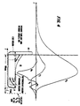
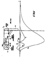
- Figure 6 illustrates the graphs of coefficients H 0 , H 2 and H 4 as a function of the coordinate Z of saddle coils 10 when spaces 100 are formed in the coils. Similar symbols and numerals in Figures 2-6 indicate similar items or functions. Coil 10 is drawn below the Z axis line of Figure 6 to show the variation of the coefficients relative to the position of space 100 is shown in Figure 6. As in Figure 5, coefficient H 4 of Figure 6 has not significant negative excursion in the intermediate yoke field region. The H 4 coefficient is mainly positive and its peak excursion has been shifted to near the yoke field entrance region and results in substantially reduced half-hour misconvergence.
- the horizontal deflection field produced by saddle coils 10 of Figures 4, 5 and 6 is predominately a pincushion-shaped field for establishing beam convergence along a horizontal axis at a vertical center of display screen 22. This can be seen by the coefficient H 2 being mainly positive.
- Figures 4-6 also show the respective locations of the beam entrance region, the intermediate region and the beam exit region coil 10. The entrance and exit regions occur where the conductors that form the windings change directions to form the corresponding four corners of saddle coil 10.
- forming spaces 100 in saddle coil 10 of Figures 3a-3c is conceptually similar to using the aforementioned tabs. This is so because a tab acts as a shunt to prevent the magnetic field produced by the windings directly behind it from affecting the electron beam. A somewhat equivalent result can be obtained by replacing the tab with a space 100 formed in the coil.
- forming spaces 100 in saddle coil 10 results in an increased concentration of wires closer to, for example, bottom edges 11a and 12a. Such increased concentration might adversely affect the third harmonic of the current distribution, but this effect may be compensated by using known techniques.
- FIG. 4 A comparison of Figures 4, 5 and 6 shows that the function H 2 (Z) does not substantially change when tabs 100' or, alternatively, spaces 100 of Figures 3a-3c, are used for correcting the misconvergence shown in Figure 1a.
- the function H 4 (Z) is significantly modified.
- function H 4 (Z) of Figure 6 may become modified by, for example, spaces 100 of Figures 3a-3c to the extent that some degradation of hour-point misconvergence occurs. Therefore, to avoid such degradation, in practice, the angle ⁇ may be slightly different than 30°, in the range between 20° and 25°.
- the function H 4 (Z) after being weighted by an appropriate power of gaussian deflection, describes the contribution of function H 4 (Z) to the half hour error.
- the gaussian deflection by definition provides error free cross hatch rasters.
- the weighted effect of function H 4 (Z) which is negative in Figure 4 has been eliminated in Figures 5 and 6 by using the tabs or winding spaces for correcting the half hour error.
Landscapes
- Video Image Reproduction Devices For Color Tv Systems (AREA)
- Color Television Systems (AREA)
- Measuring Pulse, Heart Rate, Blood Pressure Or Blood Flow (AREA)
- Devices For Indicating Variable Information By Combining Individual Elements (AREA)
- Push-Button Switches (AREA)
- Ultra Sonic Daignosis Equipment (AREA)
Claims (5)
- Selbstkonvergierende Farbanzeigevorrichtung mit einer Kathodenstrahlröhre (110) mit einem entleerten Glaskolben und mit einer Gruppe von verschiedenen farbedarstellenden Leuchtstoffelementen, die am Schirmträgerende des besagten Kolbens angeordnet sind, das einen Anzeigeschirm (22) mit einem großen Krummungsradius von 1,5R oder mehr bildet, wobei 1R der Standard-Krümmungsradius für diese Bildschirmgröße ist, und einer am gegenüberliegenden Ende (33) des besagten Kolbens angeordneten Elektronenkanonenbaugruppe (44), die zur Erzeugung von drei horizontalen, in einer Reihe liegenden Elektronenstrahlen zur Erregung von entsprechenden der besagten unterschiedlichen Farbleuchtstoffelemente angeordnet ist; einem magnetisch durchlässigen Kern (66); horizontalen und vertikalen in einem Betriebsverhältnis relativ zum besagten Kern angeordneten Ablenkspulen (77, 88) zur Erzeugung bei ihrer Erregung von horizontalen und vertikalen Ablenkfeldern, um zu bewirken, daß die besagten Strahlen einen Raster auf dem besagten Anzeigeschirm (22) abtasten, wobei das vertikale Ablenkfeld ein vorwiegend tonnenförmiges Feld und das horizontale Ablenkfeld ein vorwiegend kissenförmiges Feld aufweist, gekennzeichnet durch
zwischen den Eingangs- und Ausgangsgebieten der besagten Ablenkspulen angebrachte Mittel (100, 100') zum Verändern der Zusammensetzung der Harmonischen des besagten horizontalen Ablenkfeldes, um zu bewirken, daß das besagte horizontale Ablenkfeld eine Komponente der fünften Harmonischen aufweist, die zur Korektur des Elektronenstrahlauftreffehlers an Halbe-Stunden-Punkten auf dem besagten Raster einen bedeutend positiven Wert aufweist. - Vorrichtung nach Anspruch 1, wobei das Mittel zum Ändern der Zusammensetzung der Harmonischen einen Feldbildner (100') umfaßt.
- Vorrichtung nach Anspruch 1, wobei der besagte Feldbildner eine Zunge (100') umfaßt.
- Vorrichtung nach Anspruch 1, wobei das besagte Mittel zum Ändern der Zusammensetzung der Harmonischen (100') eine Mehrzahl von zwischen der besagten horizontalen Ablenkspule und dem besagten Glaskolben der besagten Kathodenstrahlröhre (110) angeordneten Zungen (100') umfaßt.
- Vorrichtung nach Anspruch 1, wobei die besagte horizontale Ablenkspule (77) eine Mehrzahl von Wicklungswindungen enthält, die eine komplette Schleife mit Eckenabschnitten bildet und einen Wicklungsraum enthält, der von den besagten Eckenabschnitten entfernt positioniert ist.
Priority Applications (8)
| Application Number | Priority Date | Filing Date | Title |
|---|---|---|---|
| SG9602912A SG93772A1 (en) | 1989-10-31 | 1989-10-31 | Color picture tube display device |
| EP89403010A EP0425747B1 (de) | 1989-10-31 | 1989-10-31 | Anzeigevorrichtung mit einer Farbbildröhre |
| DE68928125T DE68928125T2 (de) | 1989-10-31 | 1989-10-31 | Anzeigevorrichtung mit einer Farbbildröhre |
| AT89403010T ATE154468T1 (de) | 1989-10-31 | 1989-10-31 | Anzeigevorrichtung mit einer farbbildröhre |
| US07/599,555 US5121028A (en) | 1989-10-31 | 1990-10-18 | Deflection winding with spaces or tabs intermediate its front and rear ends |
| KR1019900017314A KR100235807B1 (ko) | 1989-10-31 | 1990-10-29 | 비디오 표시 장치 |
| JP2297040A JPH07105206B2 (ja) | 1988-10-31 | 1990-10-31 | ビデオ表示装置 |
| HK98103712A HK1004580A1 (en) | 1989-10-31 | 1998-05-01 | Color picture tube display device |
Applications Claiming Priority (2)
| Application Number | Priority Date | Filing Date | Title |
|---|---|---|---|
| SG9602912A SG93772A1 (en) | 1989-10-31 | 1989-10-31 | Color picture tube display device |
| EP89403010A EP0425747B1 (de) | 1989-10-31 | 1989-10-31 | Anzeigevorrichtung mit einer Farbbildröhre |
Publications (2)
| Publication Number | Publication Date |
|---|---|
| EP0425747A1 EP0425747A1 (de) | 1991-05-08 |
| EP0425747B1 true EP0425747B1 (de) | 1997-06-11 |
Family
ID=28043278
Family Applications (1)
| Application Number | Title | Priority Date | Filing Date |
|---|---|---|---|
| EP89403010A Expired - Lifetime EP0425747B1 (de) | 1988-10-31 | 1989-10-31 | Anzeigevorrichtung mit einer Farbbildröhre |
Country Status (7)
| Country | Link |
|---|---|
| US (1) | US5121028A (de) |
| EP (1) | EP0425747B1 (de) |
| JP (1) | JPH07105206B2 (de) |
| KR (1) | KR100235807B1 (de) |
| AT (1) | ATE154468T1 (de) |
| DE (1) | DE68928125T2 (de) |
| SG (1) | SG93772A1 (de) |
Families Citing this family (26)
| Publication number | Priority date | Publication date | Assignee | Title |
|---|---|---|---|---|
| US5376865A (en) * | 1990-07-27 | 1994-12-27 | Zenith Electronics Corporation | Non-linear yoke assembly and cathode ray tube system for correction of image geometrical distortions |
| DE69024798T2 (de) * | 1990-08-07 | 1996-08-01 | Thomson Tubes & Displays | Ablenkspule, Gerät und Methode zu deren Herstellung |
| EP0490004B1 (de) * | 1990-12-12 | 1996-03-27 | Videocolor S.A. | Ablenkjoch mit Verstärker der harmonischen Feldkomponenten |
| KR100260802B1 (ko) * | 1991-11-01 | 2000-07-01 | 요트.게.아. 롤페즈 | 편향 장치를 구비한 디스플레이 진공관 |
| KR950001742B1 (ko) * | 1992-08-03 | 1995-02-28 | 삼성전관주식회사 | 음극선관 |
| US5565731A (en) * | 1992-08-12 | 1996-10-15 | Samsung Electron Devices Co., Ltd. | Cathode ray tube |
| DE69415306T2 (de) * | 1994-06-22 | 1999-04-29 | Thomson Tubes & Displays S.A., Boulogne | Ablenkjoch |
| TW320731B (de) * | 1996-02-26 | 1997-11-21 | Victor Company Of Japan | |
| US5668436A (en) * | 1996-08-07 | 1997-09-16 | Matsushita Electronics Corporation | Cathode ray tube displays having saddle-type deflecting coils |
| FR2757679B1 (fr) * | 1996-12-20 | 1999-01-29 | Thomson Tubes & Displays | Unite de deviation pour tube a rayons cathodiques autoconvergents comportant des bobines de deviation en forme de selle |
| FR2757681B1 (fr) * | 1996-12-20 | 1999-01-29 | Thomson Tubes & Displays | Systeme de deviation pour tube a rayons cathodiques adapte au controle de la geometrie nord/sud de l'image |
| FR2757678B1 (fr) * | 1996-12-20 | 1999-01-29 | Thomson Tubes & Displays | Unite de deviation pour tube a rayons cathodiques autoconvergents comportant des bobines de deviation en forme de selle |
| FR2757680B1 (fr) * | 1996-12-20 | 1999-01-29 | Thomson Tubes & Displays | Unite de deviation pour tube a rayons cathodiques en couleurs comportant des bobines de deviation en forme de selle |
| KR19980051541A (ko) * | 1996-12-23 | 1998-09-15 | 구자홍 | 음극선관용 편향요크 |
| FR2791468B1 (fr) * | 1999-03-24 | 2001-05-11 | Thomson Tubes & Displays | Unite de deviation pour tube a rayons cathodiques autoconvergents a differentiel de trapeze reduit |
| FR2797993B1 (fr) * | 1999-08-30 | 2001-10-26 | Thomson Tubes & Displays | Unite de deflexion pour tube a rayons cathodiques comportant des bobines de deviation verticales en forme de selle |
| FR2797994B1 (fr) * | 1999-08-30 | 2001-12-07 | Thomson Tubes & Displays | Unite de deflexion pour tube a rayons cathodiques autoconvergents comportant des bobines de deviation verticales en forme de selle |
| JP2001101983A (ja) * | 1999-10-01 | 2001-04-13 | Matsushita Electronics Industry Corp | カラー受像管装置 |
| US6522060B2 (en) * | 1999-12-10 | 2003-02-18 | Lg Electronics Inc. | Deflection yoke for Braun tube |
| CN1147905C (zh) * | 2000-03-07 | 2004-04-28 | 日本胜利株式会社 | 偏转线圈及其绕线装置和绕线方法 |
| JP2001256904A (ja) * | 2000-03-08 | 2001-09-21 | Sony Corp | 偏向装置及び陰極線管装置並びにビームランディング調整方法 |
| WO2002078017A2 (en) | 2001-03-27 | 2002-10-03 | Sarnoff Corporation | Cathode ray tube deflection yoke |
| US6624560B2 (en) | 2001-05-22 | 2003-09-23 | Sony Corporation | Deflection yoke |
| JP4057887B2 (ja) * | 2001-10-30 | 2008-03-05 | 株式会社東芝 | 偏向ヨーク及び偏向ヨークを備えた陰極線管装置 |
| KR100439502B1 (ko) * | 2001-12-27 | 2004-07-09 | 삼성전기주식회사 | 권선금형 및 이를 이용한 편향요크 |
| KR20040002367A (ko) * | 2002-06-28 | 2004-01-07 | 삼성전기주식회사 | 편향요크 |
Family Cites Families (13)
| Publication number | Priority date | Publication date | Assignee | Title |
|---|---|---|---|---|
| FR2034201B1 (de) * | 1969-02-21 | 1973-10-19 | Videon Sa | |
| JPS5812976B2 (ja) * | 1975-02-07 | 1983-03-11 | ソニー株式会社 | デンシビ−ムノヒズミホセイソウチ |
| JPS52122620U (de) * | 1976-03-12 | 1977-09-17 | ||
| GB1513360A (en) * | 1977-02-09 | 1978-06-07 | Tokyo Shibaura Electric Co | Deflection yoke for colour picture tube |
| NL8004114A (nl) * | 1980-07-17 | 1982-02-16 | Philips Nv | Kleurenbeeldbuis met afbuigjuk en afbuigjuk voor een kleurenbeeldbuis. |
| JPS59230236A (ja) * | 1983-06-13 | 1984-12-24 | Sony Corp | 偏向ヨ−ク装置 |
| US4556857A (en) * | 1984-10-01 | 1985-12-03 | General Electric Company | Deflection yoke for small gun-base CRT |
| US4639703A (en) * | 1985-05-22 | 1987-01-27 | U.S. Philips Corporation | Saddle coils for electromagnetic deflection units |
| NL8600833A (nl) * | 1986-04-02 | 1987-11-02 | Philips Nv | Kathodestraalbuis. |
| US4943753A (en) * | 1987-08-13 | 1990-07-24 | International Business Machines Corporation | Magnetic shunt for deflection yokes |
| JPS6461644A (en) * | 1987-09-02 | 1989-03-08 | Nec Corp | Spread wavelength measuring instrument |
| JPS6448858U (de) * | 1987-09-21 | 1989-03-27 | ||
| NL8900213A (nl) * | 1989-01-30 | 1990-08-16 | Philips Nv | Werkwijze voor het vervaardigen van een zadelvormige afbuigspoel voor een beeldweergeefbuis. |
-
1989
- 1989-10-31 AT AT89403010T patent/ATE154468T1/de not_active IP Right Cessation
- 1989-10-31 SG SG9602912A patent/SG93772A1/en unknown
- 1989-10-31 DE DE68928125T patent/DE68928125T2/de not_active Expired - Lifetime
- 1989-10-31 EP EP89403010A patent/EP0425747B1/de not_active Expired - Lifetime
-
1990
- 1990-10-18 US US07/599,555 patent/US5121028A/en not_active Expired - Lifetime
- 1990-10-29 KR KR1019900017314A patent/KR100235807B1/ko not_active IP Right Cessation
- 1990-10-31 JP JP2297040A patent/JPH07105206B2/ja not_active Expired - Fee Related
Also Published As
| Publication number | Publication date |
|---|---|
| EP0425747A1 (de) | 1991-05-08 |
| DE68928125T2 (de) | 1997-10-16 |
| JPH03184242A (ja) | 1991-08-12 |
| US5121028A (en) | 1992-06-09 |
| ATE154468T1 (de) | 1997-06-15 |
| JPH07105206B2 (ja) | 1995-11-13 |
| DE68928125D1 (de) | 1997-07-17 |
| KR910008783A (ko) | 1991-05-31 |
| KR100235807B1 (ko) | 1999-12-15 |
| SG93772A1 (en) | 2003-01-21 |
Similar Documents
| Publication | Publication Date | Title |
|---|---|---|
| EP0425747B1 (de) | Anzeigevorrichtung mit einer Farbbildröhre | |
| CA1124308A (en) | Deflection yoke with permanent magnet raster correction | |
| US3800176A (en) | Self-converging color image display system | |
| US4231009A (en) | Deflection yoke with a magnet for reducing sensitivity of convergence to yoke position | |
| EP0853329B1 (de) | Ablenkeinheit für selbstkonvergierende Kathodenstrahlröhren mit sattelförmigen Ablenkspulen | |
| EP0613168A1 (de) | Ablenkjoch mit einem Magnetenpaar in der Nähe seiner Nebenachse | |
| US6150910A (en) | Deflection yoke with geometry distortion correction | |
| US3721930A (en) | Deflection yoke for use with in-line electron guns | |
| US5408159A (en) | Deflection yoke with a forked shunt | |
| US5306982A (en) | Field harmonic enhancer in a deflection yoke | |
| US6373180B1 (en) | Deflection yoke for a cathode-ray tube with both improved geometry and convergence | |
| US5465026A (en) | Deflection yoke with a core extension | |
| US4972519A (en) | Vertical coma correction arrangement | |
| US6630803B1 (en) | Color display device having quadrupole convergence coils | |
| EP1081737B1 (de) | Ablenkungsanordnung für selbstkonvergierende Kathodenstrahlröhren mit sattelförmigen vertikalen Ablenkspulen | |
| US6411027B1 (en) | Color display device having quadrupole convergence coils | |
| US6608436B1 (en) | Color display device having quadrupole convergence coils | |
| EP1105911A1 (de) | Farbanzeigevorrichtung mit quadrupol-konvergenzspulen | |
| USRE31552E (en) | Electron beam and deflection yoke alignment for producing convergence of plural in-line beams | |
| KR100482942B1 (ko) | 후방에 권선 공간을 구비한 새들형 편향 권선 | |
| WO2000079562A1 (en) | Color display device having quadrupole convergence coils | |
| MXPA99005755A (es) | Un yugo de desviacion con correccion de distorsion de geometria | |
| MXPA99005756A (en) | A saddle shaped deflection winding having a winding space within a predetermined angular range |
Legal Events
| Date | Code | Title | Description |
|---|---|---|---|
| PUAI | Public reference made under article 153(3) epc to a published international application that has entered the european phase |
Free format text: ORIGINAL CODE: 0009012 |
|
| AK | Designated contracting states |
Kind code of ref document: A1 Designated state(s): AT BE CH DE ES FR GB GR IT LI LU NL SE |
|
| 17P | Request for examination filed |
Effective date: 19911007 |
|
| RAP1 | Party data changed (applicant data changed or rights of an application transferred) |
Owner name: THOMSON TUBES & DISPLAYS SA |
|
| 17Q | First examination report despatched |
Effective date: 19931014 |
|
| GRAG | Despatch of communication of intention to grant |
Free format text: ORIGINAL CODE: EPIDOS AGRA |
|
| GRAH | Despatch of communication of intention to grant a patent |
Free format text: ORIGINAL CODE: EPIDOS IGRA |
|
| GRAH | Despatch of communication of intention to grant a patent |
Free format text: ORIGINAL CODE: EPIDOS IGRA |
|
| GRAA | (expected) grant |
Free format text: ORIGINAL CODE: 0009210 |
|
| AK | Designated contracting states |
Kind code of ref document: B1 Designated state(s): AT BE CH DE ES FR GB GR IT LI LU NL SE |
|
| PG25 | Lapsed in a contracting state [announced via postgrant information from national office to epo] |
Ref country code: ES Free format text: THE PATENT HAS BEEN ANNULLED BY A DECISION OF A NATIONAL AUTHORITY Effective date: 19970611 Ref country code: GR Free format text: LAPSE BECAUSE OF FAILURE TO SUBMIT A TRANSLATION OF THE DESCRIPTION OR TO PAY THE FEE WITHIN THE PRESCRIBED TIME-LIMIT Effective date: 19970611 Ref country code: LI Effective date: 19970611 Ref country code: CH Effective date: 19970611 Ref country code: AT Effective date: 19970611 Ref country code: NL Free format text: LAPSE BECAUSE OF FAILURE TO SUBMIT A TRANSLATION OF THE DESCRIPTION OR TO PAY THE FEE WITHIN THE PRESCRIBED TIME-LIMIT Effective date: 19970611 Ref country code: BE Effective date: 19970611 |
|
| REF | Corresponds to: |
Ref document number: 154468 Country of ref document: AT Date of ref document: 19970615 Kind code of ref document: T |
|
| REG | Reference to a national code |
Ref country code: CH Ref legal event code: EP |
|
| REF | Corresponds to: |
Ref document number: 68928125 Country of ref document: DE Date of ref document: 19970717 |
|
| ET | Fr: translation filed | ||
| PG25 | Lapsed in a contracting state [announced via postgrant information from national office to epo] |
Ref country code: SE Effective date: 19970911 |
|
| PG25 | Lapsed in a contracting state [announced via postgrant information from national office to epo] |
Ref country code: LU Free format text: LAPSE BECAUSE OF NON-PAYMENT OF DUE FEES Effective date: 19971031 |
|
| NLV1 | Nl: lapsed or annulled due to failure to fulfill the requirements of art. 29p and 29m of the patents act | ||
| REG | Reference to a national code |
Ref country code: CH Ref legal event code: PL |
|
| RAP2 | Party data changed (patent owner data changed or rights of a patent transferred) |
Owner name: THOMSON TUBES & DISPLAYS S.A. |
|
| PLBE | No opposition filed within time limit |
Free format text: ORIGINAL CODE: 0009261 |
|
| STAA | Information on the status of an ep patent application or granted ep patent |
Free format text: STATUS: NO OPPOSITION FILED WITHIN TIME LIMIT |
|
| 26N | No opposition filed | ||
| REG | Reference to a national code |
Ref country code: GB Ref legal event code: IF02 |
|
| REG | Reference to a national code |
Ref country code: FR Ref legal event code: D6 |
|
| REG | Reference to a national code |
Ref country code: ES Ref legal event code: GD2A Effective date: 20020206 |
|
| PGFP | Annual fee paid to national office [announced via postgrant information from national office to epo] |
Ref country code: GB Payment date: 20080929 Year of fee payment: 20 |
|
| PGFP | Annual fee paid to national office [announced via postgrant information from national office to epo] |
Ref country code: DE Payment date: 20081024 Year of fee payment: 20 |
|
| PGFP | Annual fee paid to national office [announced via postgrant information from national office to epo] |
Ref country code: IT Payment date: 20081028 Year of fee payment: 20 |
|
| PGFP | Annual fee paid to national office [announced via postgrant information from national office to epo] |
Ref country code: FR Payment date: 20081024 Year of fee payment: 20 |
|
| REG | Reference to a national code |
Ref country code: GB Ref legal event code: PE20 Expiry date: 20091030 |
|
| PG25 | Lapsed in a contracting state [announced via postgrant information from national office to epo] |
Ref country code: GB Free format text: LAPSE BECAUSE OF EXPIRATION OF PROTECTION Effective date: 20091030 |