EP0424894B1 - Verfahren zum Einbringen eines Behandlungsmediums in den Abgasstrom bei Verbrennungsprozessen - Google Patents
Verfahren zum Einbringen eines Behandlungsmediums in den Abgasstrom bei Verbrennungsprozessen Download PDFInfo
- Publication number
- EP0424894B1 EP0424894B1 EP90120346A EP90120346A EP0424894B1 EP 0424894 B1 EP0424894 B1 EP 0424894B1 EP 90120346 A EP90120346 A EP 90120346A EP 90120346 A EP90120346 A EP 90120346A EP 0424894 B1 EP0424894 B1 EP 0424894B1
- Authority
- EP
- European Patent Office
- Prior art keywords
- treating agent
- function
- carrier medium
- treatment medium
- medium
- Prior art date
- Legal status (The legal status is an assumption and is not a legal conclusion. Google has not performed a legal analysis and makes no representation as to the accuracy of the status listed.)
- Expired - Lifetime
Links
Images


Classifications
-
- F—MECHANICAL ENGINEERING; LIGHTING; HEATING; WEAPONS; BLASTING
- F23—COMBUSTION APPARATUS; COMBUSTION PROCESSES
- F23J—REMOVAL OR TREATMENT OF COMBUSTION PRODUCTS OR COMBUSTION RESIDUES; FLUES
- F23J15/00—Arrangements of devices for treating smoke or fumes
- F23J15/003—Arrangements of devices for treating smoke or fumes for supplying chemicals to fumes, e.g. using injection devices
-
- B—PERFORMING OPERATIONS; TRANSPORTING
- B01—PHYSICAL OR CHEMICAL PROCESSES OR APPARATUS IN GENERAL
- B01D—SEPARATION
- B01D53/00—Separation of gases or vapours; Recovering vapours of volatile solvents from gases; Chemical or biological purification of waste gases, e.g. engine exhaust gases, smoke, fumes, flue gases, aerosols
- B01D53/34—Chemical or biological purification of waste gases
- B01D53/46—Removing components of defined structure
- B01D53/54—Nitrogen compounds
- B01D53/56—Nitrogen oxides
-
- F—MECHANICAL ENGINEERING; LIGHTING; HEATING; WEAPONS; BLASTING
- F23—COMBUSTION APPARATUS; COMBUSTION PROCESSES
- F23J—REMOVAL OR TREATMENT OF COMBUSTION PRODUCTS OR COMBUSTION RESIDUES; FLUES
- F23J7/00—Arrangement of devices for supplying chemicals to fire
-
- F—MECHANICAL ENGINEERING; LIGHTING; HEATING; WEAPONS; BLASTING
- F23—COMBUSTION APPARATUS; COMBUSTION PROCESSES
- F23J—REMOVAL OR TREATMENT OF COMBUSTION PRODUCTS OR COMBUSTION RESIDUES; FLUES
- F23J2219/00—Treatment devices
- F23J2219/20—Non-catalytic reduction devices
Definitions
- the invention relates to a method for introducing a treatment medium in the form of chemicals into the exhaust gas stream in combustion processes by means of a carrier medium through an atomizing nozzle to reduce the nitrogen oxide concentration.
- the uniform distribution over the entire flue gas flow is achieved on the one hand by arranging several nozzles across the cross section of the flue gas duct, and on the other hand - and this is generally considered to be of particular importance - by using two-substance nozzles, such as the one used are known for example from WO-A-89/07982, which use steam or compressed air as an atomizing medium is fed.
- two-substance nozzles such as the one used are known for example from WO-A-89/07982
- using your own atomizing medium has several disadvantages. Compressed air or steam are relatively expensive media because they always require high amounts of energy and, if steam is used, treated steam boiler feed water.
- Piping of these media down to the individual nozzles is complex, since either heat-insulated pipes in the case of steam and / or relatively large pipe cross sections have to be used to reduce the pressure loss in the system.
- the expansion of the media at the nozzle outlet or the media flows in the lines generate a relatively high noise level, which often even makes sound insulation necessary.
- the use of two-component nozzles also has the disadvantage that the carrier medium, which serves to atomize the treatment medium, namely the chemicals, must be used in large quantities, since the atomization is brought about due to the kinetic energy of the carrier medium. This results in a large dilution of the flue gases even with small quantities to be atomized.
- the object of the invention is to introduce a treatment medium, i. H. To enable certain chemicals in the flue gas with high efficiency with little expenditure of energy and little construction effort.
- this object is achieved according to the invention in that the carrier medium is brought to a pressure level necessary for atomization and is fed to an atomizing nozzle having a single nozzle opening and that the treatment medium is fed to the atomizing nozzle, which is mixed with the carrier medium in any quantity ratio immediately before it emerges from the nozzle opening, the treatment medium is brought to the pressure level of the carrier medium before the mixing process.
- the treatment medium is not atomized on the basis of kinetic energy which has to be applied by means of the carrier medium, but rather on account of the pressure change before and after the nozzle opening, which leads to a substantial reduction in the carrier medium. This is necessary in order to operate the nozzle with a certain throughput quantity, irrespective of the proportion and the quantity of the treatment medium.
- the carrier medium can serve to cool the atomizing nozzle if the atomization of the treatment medium is stopped completely. In this case, the nozzle would be affected by the heat in the furnace, which would be avoided by atomizing the carrier medium.
- the amount of the mixed treatment medium can be adjusted depending on the NO x gas concentration in the treated flue gas stream.
- the NO x gas concentration is therefore measured in a range in which the treatment medium is already located and the corresponding chemical reaction has taken place.
- the amount of treatment medium can also be adjusted depending on the amount of exhaust gas.
- the atomization pressure can be set as a function of the amount of exhaust gas.
- the treatment medium is supplied to the atomizing nozzle in a concentrated form, the concentration being adjustable depending on the quantity required. In general, it can be concentrated up to the respective solution limit of the treatment medium.
- Ammonia, ammonia, urea or calcium cyanamide, for example, can be used as the treatment medium. With this treatment medium it is recommended as a carrier medium To use water.
- 1 shows the schematic flow diagram for the carrier medium and the treatment medium.
- 1 designates a storage container for the chemical to be introduced into the combustion chamber, which in the example is in a powdery state in this container.
- the chemical passes through a lock 2 into a storage container 3, in which water 4 is introduced via a valve 4 to dissolve the chemical.
- a stirrer 5 By means of a stirrer 5, the solution or suspension used is constantly kept circulating in order to prevent segregation.
- 6 denotes a level monitoring system, which ensures the supply of chemicals from the storage container 1 when the minimum level is undershot.
- a float 7 monitors the liquid level in the reservoir 3 and influences the valve 4 for supplying water to the reservoir 3.
- the treatment medium is pumped to a number of atomizing nozzles 10 by means of a pump 9 supplied, which are arranged in the wall 11 of a combustion chamber 12 distributed in several levels.
- a check valve 14 is provided in order to prevent the back flow of carrier medium into the storage container 3.
- the carrier medium which is water in the present example, is fed by means of pumps 15 via valves 16 to a pressure line 17 which leads to the atomizing nozzles 10.
- a check valve 18 and a pressure measuring point 19 are provided within the pressure line.
- Another pressure measuring point 20 monitors the pressure in the atomizing nozzles 10.
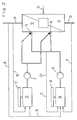
- the control system with the aid of which the introduction of the treatment medium is controlled is now explained with reference to FIG. 2.
- the treatment medium and carrier medium are guided to the atomizing nozzles 10 by means of the pumps 9 and 15, which open into the combustion chamber 12.
- the boiler With 21 the boiler is designated as a whole, to which 22 feed water is supplied via a line.
- the steam extraction line is designated by 23, while the reference symbol 24 symbolizes the flue gas outlet.
- the delivery rate of the treatment medium ie the chemical, which is provided for introduction into the combustion chamber 12, is set by means of a control system 25.
- the regulation takes place as a function of the NO x gas concentration in the flue gas 24, the measurement of this gas concentration being carried out at a point in which flue gas that has already been treated, ie, treated with treatment medium, is located.
- This signal is sent via line 26 fed to the control system 25.
- a setpoint generator 27 for the setpoint of the NO x content in the flue gas the value is set which, when exceeded, starts the supply of treatment medium into the combustion chamber for the treatment of the flue gas.
- control system 25 can also control the amount of treatment medium supplied as a function of the flue gas volume flow, this value being measured in the flue gas outlet 24 and being fed to the control system 25 through the line 28.
- This measured value relating to the volume flow of the flue gas is also fed via line 28 to a further control system 29 which is provided for setting the atomizing pressure.
- a setpoint generator 30 for the atomizing pressure specifies a fixed value which is matched to the nozzle configuration, or the atomizing pressure can be set as a function of the flue gas volume flow or the steam boiler load.
- the measured value relating to the flue gas volume flow is supplied via line 28, while the measured value relating to the boiler load is supplied via line 31.
- 32 denotes a signal line which supplies the atomization pressure actually prevailing to the control system 29.
- FIG. 3 shows a schematic section through an atomizing nozzle 10.
- This has a nozzle body 33 which on the one hand comprises supply lines 34 and 35 and on the other hand a mixing chamber 36.
- the feed lines 34 and 35 open into the mixing chamber 36 and are connected at their other ends to the supply line 13 for the treatment medium and to the supply line 17 for the carrier medium.
- a nozzle head 37 which can be screwed onto the nozzle body 33 and has an atomization bore 38 from which the mixture of carrier medium and treatment medium emerges under pressure and due to the prevailing pressure difference inside and outside the atomizing nozzle is atomized.
Landscapes
- Engineering & Computer Science (AREA)
- Chemical & Material Sciences (AREA)
- Chemical Kinetics & Catalysis (AREA)
- General Chemical & Material Sciences (AREA)
- Mechanical Engineering (AREA)
- General Engineering & Computer Science (AREA)
- Health & Medical Sciences (AREA)
- Biomedical Technology (AREA)
- Environmental & Geological Engineering (AREA)
- Analytical Chemistry (AREA)
- Oil, Petroleum & Natural Gas (AREA)
- Treating Waste Gases (AREA)
- Chimneys And Flues (AREA)
- Gas Separation By Absorption (AREA)
- Incineration Of Waste (AREA)
Applications Claiming Priority (2)
| Application Number | Priority Date | Filing Date | Title |
|---|---|---|---|
| DE3935402A DE3935402C1 (da) | 1989-10-24 | 1989-10-24 | |
| DE3935402 | 1989-10-24 |
Publications (2)
| Publication Number | Publication Date |
|---|---|
| EP0424894A1 EP0424894A1 (de) | 1991-05-02 |
| EP0424894B1 true EP0424894B1 (de) | 1994-07-20 |
Family
ID=6392101
Family Applications (1)
| Application Number | Title | Priority Date | Filing Date |
|---|---|---|---|
| EP90120346A Expired - Lifetime EP0424894B1 (de) | 1989-10-24 | 1990-10-23 | Verfahren zum Einbringen eines Behandlungsmediums in den Abgasstrom bei Verbrennungsprozessen |
Country Status (9)
| Country | Link |
|---|---|
| US (1) | US5260042A (da) |
| EP (1) | EP0424894B1 (da) |
| JP (1) | JPH07108369B2 (da) |
| AT (1) | ATE108689T1 (da) |
| BR (1) | BR9005347A (da) |
| CA (1) | CA2028391C (da) |
| DE (1) | DE3935402C1 (da) |
| DK (1) | DK0424894T3 (da) |
| ES (1) | ES2057325T3 (da) |
Families Citing this family (13)
| Publication number | Priority date | Publication date | Assignee | Title |
|---|---|---|---|---|
| ATA219190A (de) * | 1990-10-30 | 1994-11-15 | Steirische Magnesit Ind Ag | Verfahren und vorrichtung zum einduesen von festen additiven in verbrennungsanlagen |
| DE4139862A1 (de) * | 1991-12-03 | 1993-06-09 | Martin Gmbh Fuer Umwelt- Und Energietechnik, 8000 Muenchen, De | Verfahren zur regelung der eingabemenge eines behandlungsmediums zur verminderung des stickoxidgehaltes in den abgasen von verbrennungsprozessen |
| DK171982B1 (da) * | 1992-03-27 | 1997-09-08 | Smidth & Co As F L | Fremgangsmåde og anlæg til selektiv reduktion af NO-indholdet i røggas fra et ovnanlæg |
| DE59506772D1 (de) * | 1994-03-21 | 1999-10-14 | Seghers Better Technology Grou | Verfahren und vorrichtung zum einbringen eines flüssigen oder gasförmigen behandlungsmediums in einen rauchgasstrom |
| US5707593A (en) * | 1996-12-31 | 1998-01-13 | Wang Chi | Energy self-sustainable reactor for gasifying engine particulates and unburned hydrocarbons |
| DE19713136A1 (de) * | 1997-03-27 | 1998-10-01 | Abb Patent Gmbh | Verfahren zur selektiven Gasphasenreaktion |
| US5976475A (en) * | 1997-04-02 | 1999-11-02 | Clean Diesel Technologies, Inc. | Reducing NOx emissions from an engine by temperature-controlled urea injection for selective catalytic reduction |
| US6063350A (en) * | 1997-04-02 | 2000-05-16 | Clean Diesel Technologies, Inc. | Reducing nox emissions from an engine by temperature-controlled urea injection for selective catalytic reduction |
| DE19728344A1 (de) * | 1997-07-03 | 1999-01-07 | Abb Research Ltd | Verfahren und Vorrichtung zur Entstickung der Abgase von Verbrennungsanlagen |
| US6279603B1 (en) * | 1998-10-01 | 2001-08-28 | Ambac International | Fluid-cooled injector |
| US6761868B2 (en) * | 2001-05-16 | 2004-07-13 | The Chemithon Corporation | Process for quantitatively converting urea to ammonia on demand |
| US6887284B2 (en) * | 2002-07-12 | 2005-05-03 | Dannie B. Hudson | Dual homogenization system and process for fuel oil |
| EP3421744B1 (en) | 2005-12-22 | 2022-05-04 | Emitec Denmark A/S | A fluid transfer system and method |
Citations (1)
| Publication number | Priority date | Publication date | Assignee | Title |
|---|---|---|---|---|
| WO1989007982A1 (en) * | 1988-02-26 | 1989-09-08 | Fuel Tech, Inc. | Process and injector for reducing the concentration of pollutants in an effluent |
Family Cites Families (14)
| Publication number | Priority date | Publication date | Assignee | Title |
|---|---|---|---|---|
| US3565575A (en) * | 1968-05-22 | 1971-02-23 | Chemical Construction Corp | Removal of nitrogen oxides from a gas stream |
| JPS4924342B1 (da) * | 1970-12-04 | 1974-06-21 | ||
| JPS5326258A (en) * | 1976-08-24 | 1978-03-10 | Ishikawajima Harima Heavy Ind Co Ltd | Denitrating method of spraying type |
| JPS5394258A (en) * | 1977-01-31 | 1978-08-18 | Kurabo Ind Ltd | Control method and apparatus for nitrogen oxides removing apparatus |
| JPS53109866A (en) * | 1977-03-09 | 1978-09-26 | Babcock Hitachi Kk | Controlling method for injection of reducing agnet for nox |
| JPS53131963A (en) * | 1977-04-25 | 1978-11-17 | Kurabo Ind Ltd | Device for controlling nitrogen oxide removing device |
| DE3337793A1 (de) * | 1983-10-18 | 1985-05-02 | L. & C. Steinmüller GmbH, 5270 Gummersbach | Verfahren zur regelung der zugabemenge an reduktionsmittel bei der katalytischen reduktion von in rauchgasen enthaltenem no(pfeil abwaerts)x(pfeil abwaerts) |
| DE3502788A1 (de) * | 1985-01-28 | 1986-07-31 | Saacke GmbH & Co KG, 2800 Bremen | Verfahren und vorrichtung zum reduzieren der schadstoffemission von feuerungsanlagen |
| JPS62213824A (ja) * | 1986-03-14 | 1987-09-19 | Mitsubishi Heavy Ind Ltd | 脱硝装置のnh3注入制御装置 |
| DE3721104A1 (de) * | 1986-07-01 | 1988-01-14 | Zahnradfabrik Friedrichshafen | Nitrierhaerteanlage mit abgasaufbereitung |
| EP0337515A3 (en) * | 1986-10-07 | 1989-11-02 | Nippon Kokan Kabushiki Kaisha | Method and apparatus for controlling the injection amount of ammonia for denitration of exhaust gas |
| DE3800730A1 (de) * | 1987-02-11 | 1988-08-25 | Babcock Anlagen Ag | Verfahren zum einmischen von ammoniak in einen rauchgasstrom |
| US4780289A (en) * | 1987-05-14 | 1988-10-25 | Fuel Tech, Inc. | Process for nitrogen oxides reduction and minimization of the production of other pollutants |
| DE3705604A1 (de) * | 1987-02-21 | 1988-09-01 | Lentjes Ag | Verfahren zum einbringen von reaktanden in einen fluidstrom |
-
1989
- 1989-10-24 DE DE3935402A patent/DE3935402C1/de not_active Expired - Lifetime
-
1990
- 1990-10-19 US US07/601,215 patent/US5260042A/en not_active Expired - Lifetime
- 1990-10-22 JP JP2284120A patent/JPH07108369B2/ja not_active Expired - Fee Related
- 1990-10-23 AT AT90120346T patent/ATE108689T1/de not_active IP Right Cessation
- 1990-10-23 BR BR909005347A patent/BR9005347A/pt not_active IP Right Cessation
- 1990-10-23 DK DK90120346.3T patent/DK0424894T3/da active
- 1990-10-23 EP EP90120346A patent/EP0424894B1/de not_active Expired - Lifetime
- 1990-10-23 ES ES90120346T patent/ES2057325T3/es not_active Expired - Lifetime
- 1990-10-24 CA CA002028391A patent/CA2028391C/en not_active Expired - Lifetime
Patent Citations (1)
| Publication number | Priority date | Publication date | Assignee | Title |
|---|---|---|---|---|
| WO1989007982A1 (en) * | 1988-02-26 | 1989-09-08 | Fuel Tech, Inc. | Process and injector for reducing the concentration of pollutants in an effluent |
Also Published As
| Publication number | Publication date |
|---|---|
| DK0424894T3 (da) | 1994-11-14 |
| BR9005347A (pt) | 1991-09-17 |
| ES2057325T3 (es) | 1994-10-16 |
| ATE108689T1 (de) | 1994-08-15 |
| US5260042A (en) | 1993-11-09 |
| CA2028391A1 (en) | 1991-04-25 |
| DE3935402C1 (da) | 1991-02-21 |
| JPH07108369B2 (ja) | 1995-11-22 |
| EP0424894A1 (de) | 1991-05-02 |
| CA2028391C (en) | 1998-05-12 |
| JPH04180816A (ja) | 1992-06-29 |
Similar Documents
| Publication | Publication Date | Title |
|---|---|---|
| EP0424894B1 (de) | Verfahren zum Einbringen eines Behandlungsmediums in den Abgasstrom bei Verbrennungsprozessen | |
| EP0624391B1 (de) | Verfahren und Vorrichtung zur Entstickung von Rauchgasen | |
| DE3728557C2 (da) | ||
| EP0364712B1 (de) | Verfahren zum Entfernen von Stickoxyden aus Rauchgasen | |
| EP3717139B1 (de) | Vorrichtung und verfahren zur odorierung eines gasstroms in einer gasleitung | |
| DE3415594C2 (da) | ||
| EP3969547A1 (de) | Injektionseinrichtung zur injektion eines flüssigen odoriermittels in einen durch eine gasleitung strömenden gasstrom, deren verwendung und verfahren zu deren herstellung | |
| DE3939197C3 (de) | Verfahren und Vorrichtung zur Minderung der Stickoxid-Konzentration im Abgasstrom von Verbrennungsprozessen | |
| DE102017001025A1 (de) | Düsenlanze, Verbrennungsanlage und Verfahren zur Abgasbehandlung | |
| DE3935400C1 (da) | ||
| DE19930051C2 (de) | Vorrichtung und Verfahren zur Durchführung eines Wasser-Quenches | |
| DE3132994A1 (de) | Verfahren und vorrichtung zum mischen von fluessigkeiten | |
| DE3935401C1 (da) | ||
| WO2003049869A1 (de) | Vorrichtung und verfahren zum zerstäuben einer flüssigkeit in ein volumen | |
| DE2452115A1 (de) | Verfahren zur bildung einer mischung einer brennbaren fluessigkeit mit einem hilfsfluidum | |
| DE4401097B4 (de) | Verfahren zur Reduzierung der NOX-Emissionen sowie Vorrichtung zur Durchführung des Verfahrens | |
| DE10030775C1 (de) | Verfahren zur Dosierung von Flüssigkeiten | |
| WO1979000145A1 (en) | Process for disinfecting liquids and device for applying said process | |
| DE2806479C2 (de) | Verfahren und Vorrichtung für das Abscheiden von Flugasche aus Rauchgasen | |
| DE19713136A1 (de) | Verfahren zur selektiven Gasphasenreaktion | |
| DE10020088A1 (de) | Vorrichtung zum kontinuierlichen dosierten Einbringen von Flüssigkeit in einen Raum | |
| DE2156699C3 (de) | Verfahren und Vorrichtung zum automatischen Regenerieren von KupferchloridÄtzmittellösungen | |
| AT47637B (de) | Verfahren zum Imprägnieren von Wasser mit Gasen. | |
| DE1902504C3 (de) | Verfahren und Vorrichtung zum Einsprühen einer wässrigen Aufschwemmung pulverförmiger Additive in den Feuerraum von Kesselanlagen | |
| DE8403339U1 (de) | Vorrichtung zur Herstellung von halbsynthetischen Schutz- und Reaktionsgasen, insbesondere zur Wärmebehandlung von Stahl- und Metallwerkstoffen, bestehend aus einer Mischung unterschiedlich wählbarer Mengen von Stickstoff, Wasserstoff, Kohlenmonoxyd, Kohlendioxyd sowie Wasserdampf |
Legal Events
| Date | Code | Title | Description |
|---|---|---|---|
| PUAI | Public reference made under article 153(3) epc to a published international application that has entered the european phase |
Free format text: ORIGINAL CODE: 0009012 |
|
| AK | Designated contracting states |
Kind code of ref document: A1 Designated state(s): AT BE CH DK ES FR GB IT LI LU NL SE |
|
| 17P | Request for examination filed |
Effective date: 19910321 |
|
| 17Q | First examination report despatched |
Effective date: 19930608 |
|
| GRAA | (expected) grant |
Free format text: ORIGINAL CODE: 0009210 |
|
| AK | Designated contracting states |
Kind code of ref document: B1 Designated state(s): AT BE CH DK ES FR GB IT LI LU NL SE |
|
| REF | Corresponds to: |
Ref document number: 108689 Country of ref document: AT Date of ref document: 19940815 Kind code of ref document: T |
|
| ITF | It: translation for a ep patent filed |
Owner name: STUDIO JAUMANN |
|
| REG | Reference to a national code |
Ref country code: ES Ref legal event code: FG2A Ref document number: 2057325 Country of ref document: ES Kind code of ref document: T3 |
|
| ET | Fr: translation filed | ||
| GBT | Gb: translation of ep patent filed (gb section 77(6)(a)/1977) |
Effective date: 19941006 |
|
| REG | Reference to a national code |
Ref country code: DK Ref legal event code: T3 |
|
| EAL | Se: european patent in force in sweden |
Ref document number: 90120346.3 |
|
| PLBE | No opposition filed within time limit |
Free format text: ORIGINAL CODE: 0009261 |
|
| STAA | Information on the status of an ep patent application or granted ep patent |
Free format text: STATUS: NO OPPOSITION FILED WITHIN TIME LIMIT |
|
| 26N | No opposition filed | ||
| REG | Reference to a national code |
Ref country code: GB Ref legal event code: IF02 |
|
| PGFP | Annual fee paid to national office [announced via postgrant information from national office to epo] |
Ref country code: SE Payment date: 20091014 Year of fee payment: 20 Ref country code: DK Payment date: 20091014 Year of fee payment: 20 Ref country code: AT Payment date: 20091015 Year of fee payment: 20 Ref country code: LU Payment date: 20091120 Year of fee payment: 20 Ref country code: CH Payment date: 20091026 Year of fee payment: 20 Ref country code: ES Payment date: 20091023 Year of fee payment: 20 |
|
| PGFP | Annual fee paid to national office [announced via postgrant information from national office to epo] |
Ref country code: NL Payment date: 20091016 Year of fee payment: 20 |
|
| PGFP | Annual fee paid to national office [announced via postgrant information from national office to epo] |
Ref country code: IT Payment date: 20091028 Year of fee payment: 20 Ref country code: FR Payment date: 20091110 Year of fee payment: 20 Ref country code: GB Payment date: 20091022 Year of fee payment: 20 |
|
| PGFP | Annual fee paid to national office [announced via postgrant information from national office to epo] |
Ref country code: BE Payment date: 20091130 Year of fee payment: 20 |
|
| REG | Reference to a national code |
Ref country code: CH Ref legal event code: PL |
|
| BE20 | Be: patent expired |
Owner name: *MARTIN G.M.B.H. FUR UMWELT- UND ENERGIETECHNIK Effective date: 20101023 |
|
| REG | Reference to a national code |
Ref country code: NL Ref legal event code: V4 Effective date: 20101023 |
|
| REG | Reference to a national code |
Ref country code: DK Ref legal event code: EUP |
|
| REG | Reference to a national code |
Ref country code: GB Ref legal event code: PE20 Expiry date: 20101022 |
|
| EUG | Se: european patent has lapsed | ||
| PG25 | Lapsed in a contracting state [announced via postgrant information from national office to epo] |
Ref country code: NL Free format text: LAPSE BECAUSE OF EXPIRATION OF PROTECTION Effective date: 20101023 |
|
| REG | Reference to a national code |
Ref country code: ES Ref legal event code: FD2A Effective date: 20110222 |
|
| PG25 | Lapsed in a contracting state [announced via postgrant information from national office to epo] |
Ref country code: GB Free format text: LAPSE BECAUSE OF EXPIRATION OF PROTECTION Effective date: 20101022 |
|
| PG25 | Lapsed in a contracting state [announced via postgrant information from national office to epo] |
Ref country code: ES Free format text: LAPSE BECAUSE OF EXPIRATION OF PROTECTION Effective date: 20101024 |