EP0423815B1 - Befestigung eines Stützfusses eines Dachgepäckträgers - Google Patents
Befestigung eines Stützfusses eines Dachgepäckträgers Download PDFInfo
- Publication number
- EP0423815B1 EP0423815B1 EP90120100A EP90120100A EP0423815B1 EP 0423815 B1 EP0423815 B1 EP 0423815B1 EP 90120100 A EP90120100 A EP 90120100A EP 90120100 A EP90120100 A EP 90120100A EP 0423815 B1 EP0423815 B1 EP 0423815B1
- Authority
- EP
- European Patent Office
- Prior art keywords
- support leg
- clamping
- support
- clamping piece
- roof
- Prior art date
- Legal status (The legal status is an assumption and is not a legal conclusion. Google has not performed a legal analysis and makes no representation as to the accuracy of the status listed.)
- Expired - Lifetime
Links
- 238000000465 moulding Methods 0.000 claims 1
- 230000000284 resting effect Effects 0.000 claims 1
- 239000000945 filler Substances 0.000 description 3
- 238000009434 installation Methods 0.000 description 2
- 230000002411 adverse Effects 0.000 description 1
- 238000013459 approach Methods 0.000 description 1
- 238000010276 construction Methods 0.000 description 1
- 238000004049 embossing Methods 0.000 description 1
- 238000007373 indentation Methods 0.000 description 1
- 230000003993 interaction Effects 0.000 description 1
- 238000000034 method Methods 0.000 description 1
Images


Classifications
-
- F—MECHANICAL ENGINEERING; LIGHTING; HEATING; WEAPONS; BLASTING
- F16—ENGINEERING ELEMENTS AND UNITS; GENERAL MEASURES FOR PRODUCING AND MAINTAINING EFFECTIVE FUNCTIONING OF MACHINES OR INSTALLATIONS; THERMAL INSULATION IN GENERAL
- F16B—DEVICES FOR FASTENING OR SECURING CONSTRUCTIONAL ELEMENTS OR MACHINE PARTS TOGETHER, e.g. NAILS, BOLTS, CIRCLIPS, CLAMPS, CLIPS OR WEDGES; JOINTS OR JOINTING
- F16B5/00—Joining sheets or plates, e.g. panels, to one another or to strips or bars parallel to them
- F16B5/02—Joining sheets or plates, e.g. panels, to one another or to strips or bars parallel to them by means of fastening members using screw-thread
- F16B5/025—Joining sheets or plates, e.g. panels, to one another or to strips or bars parallel to them by means of fastening members using screw-thread specially designed to compensate for misalignement or to eliminate unwanted play
-
- B—PERFORMING OPERATIONS; TRANSPORTING
- B60—VEHICLES IN GENERAL
- B60R—VEHICLES, VEHICLE FITTINGS, OR VEHICLE PARTS, NOT OTHERWISE PROVIDED FOR
- B60R9/00—Supplementary fittings on vehicle exterior for carrying loads, e.g. luggage, sports gear or the like
- B60R9/04—Carriers associated with vehicle roof
- B60R9/058—Carriers associated with vehicle roof characterised by releasable attaching means between carrier and roof
-
- F—MECHANICAL ENGINEERING; LIGHTING; HEATING; WEAPONS; BLASTING
- F16—ENGINEERING ELEMENTS AND UNITS; GENERAL MEASURES FOR PRODUCING AND MAINTAINING EFFECTIVE FUNCTIONING OF MACHINES OR INSTALLATIONS; THERMAL INSULATION IN GENERAL
- F16B—DEVICES FOR FASTENING OR SECURING CONSTRUCTIONAL ELEMENTS OR MACHINE PARTS TOGETHER, e.g. NAILS, BOLTS, CIRCLIPS, CLAMPS, CLIPS OR WEDGES; JOINTS OR JOINTING
- F16B2/00—Friction-grip releasable fastenings
- F16B2/02—Clamps, i.e. with gripping action effected by positive means other than the inherent resistance to deformation of the material of the fastening
- F16B2/14—Clamps, i.e. with gripping action effected by positive means other than the inherent resistance to deformation of the material of the fastening using wedges
Definitions
- the invention relates to an attachment of a support foot of a roof rack in a motor vehicle body with a rain gutter and a threaded bushing in the roof panel for the attachment of the roof rack by means of a screw.
- a support fitting is fixed by means of the fastening screw, which is provided for supporting the support foot and for receiving a locking member with an outwardly projecting support flange which, because of the possibility of accommodating the support foot and the locking member protrudes relatively far from the roof, so that either an indentation is formed in the roof area or a relatively large distance between the door frame and roof sheet must remain. Since the support foot is not attached directly to the roof, but is supported on the support fitting and fixed by means of the locking member, not only is the structural complexity increased, but also the rigidity of this fastening arrangement and thus the resilience of the Roof rack adversely affected.
- the object of the invention is to provide an attachment of a support leg of a roof rack that takes up little space, requires only a few components and is therefore simple in construction, and enables a secure and rigid attachment of the roof rack to the motor vehicle body, the fixing of the support foot due to the simplicity of attachment can be carried out easily and quickly.
- the support foot Due to the design of the support surfaces, a conical clamping fit is created for the clamping piece, so that the support foot is pressed downwards against the rain gutter and against the roof sheet by the interaction of the supporting surfaces with the clamping surfaces of the clamping piece. As a result, the support leg, which can have a correspondingly long contact surface on the rain gutter, is held on the body so that it cannot tip over. Since the support surfaces protrude only slightly from the support foot, you need only a small amount of space.
- the support foot can be made of a relatively thin sheet with a thickness of a few millimeters, so that it only requires a small gap between the roof sheet and the door frame.
- the strength of the support leg is still guaranteed because it only needs to be made thin in the area covered by the door frame while it is outside the Door frame can be designed as a stable thicker profile.
- no additional locking member and no additional screw fastening is necessary in addition to the fastening screw, so that there is a stable arrangement which requires little space and can be quickly attached to the body. It is not necessary to provide bulges in the roof or to leave a large gap between the door frame and the roof structure. Bulges in the roof area have the disadvantage that they have to be filled with filler pieces when the roof rack is not being used in order to restore the continuous roof shape. These fillers are impractical in that they have to be removed and kept separate during use of the roof rack, with the risk of being lost or of the user forgetting to reinsert these fillers after the roof rack has been removed.
- a simple design of the support foot results from the fact that the support surfaces are formed on clamping blocks which are fastened to the support foot on opposite sides of the support foot opening. In this way, precisely machined support surfaces can be carried out without the need for expensive embossing tools with the correspondingly large presses, the use of which could only be justified under very large quantities.
- a dimensionally accurate arrangement of the blocks on the support foot is achieved in an advantageous development of the invention in that the clamping blocks with the thickness of the support foot engage adapted approaches in the support leg opening. Because of this positive locking, the clamping blocks can be fastened by means of a single screw or rivet arranged outside the line of symmetry of the respective clamping block.
- the support surfaces form an angle of 60 ° with respect to one another in the direction of the end of the support leg, this not only produces a sufficient force component in the direction of the end of the support leg for pressing it against the rain gutter, but also a sufficiently stable contact pressure of the support leg against the roof panel achieved.
- this creates the prerequisite for a further advantageous embodiment of the invention, which consists in that the clamping piece has three clamping surfaces with the same length in the circumferential direction of the clamping piece, each of which enclose an angle of 60 ° with one another.
- This clamping piece is symmetrical with the same side lengths, which does not result in a specific installation position, as is the case with an asymmetrical clamping piece.
- the clamping piece can also be designed asymmetrically, in which case it then has only two clamping surfaces corresponding to the support surfaces. This configuration is preferred when there is only a small amount of space available.
- the area of the support foot opening is larger than the area of the clamping piece in plan view and in the operating position, the edges of the support leg opening run parallel to the edges of the clamping piece, so there is the possibility that the clamping piece can dip into the support foot and there is sufficient freedom of movement during the clamping process. This reduces the space required between the roof structure and the door frame.
- the fastening screw can have a flat countersunk head which interacts with an adapted conical seat in the clamping piece.
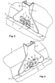
- FIG. 1 shows the arrangement of two support bars 1 on the roof 2 of a motor vehicle body, the door frames in the region of the attachment points of these support bars being shown broken away. It can be seen that the support bars 1 are fastened with their support feet 3 to the roof 2 of the motor vehicle body by means of screws 4.
- the support foot 3 with its support lugs 5 is supported on the gutter 6 of the motor vehicle body.
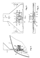
- the support foot 3 has an opening 7 in the form of a triangular cutout, on the two edges of which are provided symmetrically to the longitudinal axis 8 of the support foot, support surfaces 9 are provided, which are formed on clamping blocks 10.
- the clamping blocks 10 engage with an attachment 11 in a form-fitting manner in the opening 7 of the support foot 3 and are each attached to the support leg with an asymmetrically arranged screw 12 with respect to the respective clamping block 10.
- the support surfaces 9 form an angle of 60 ° to one another and run towards one another symmetrically with respect to the line of symmetry 8 of the support foot 3 in the direction of its end.
- These support surfaces 9 are also inclined outwards, that is to say they are arranged in a divergent manner, so that they form a conically tapering seat for a clamping piece 13 which, in the embodiment according to FIGS. 2 to 5, is formed symmetrically in the manner of an equilateral triangle.
- the clamping piece On all three sides, the clamping piece has conically tapering clamping surfaces 14, the inclination of which is adapted to the supporting surfaces 9. Due to the symmetrical design, the clamping piece 13 has no preferred installation position.
- This clamping piece 13 is pressed against the clamping blocks 10 by means of the fastening screw 4, which can be screwed into a threaded bushing 15 arranged on the inside of the roof plate 2.
- the fastening screw 4 has a flat countersunk head 16 which interacts with a conical seat 17 in the clamping piece 13. Due to the divergent arrangement of the support surfaces 9, the support foot is pressed firmly against the roof panel 2. Because of the support surfaces 9 tapering downwards, the support foot 3 with its support lugs 5 is pressed against the rain gutter 6, whereby a particularly firm hold of the support foot 3 on the roof of the motor vehicle body is achieved.
- clamping piece 13 'according to FIGS. 6 to 9 is not symmetrical and only has clamping surfaces 14' on its two side edges, which cooperate with the clamping surfaces 9 'of the clamping blocks 10'.
- the clamping surfaces 9 ' run towards each other at a larger angle than is the case with the embodiment according to FIGS. 2 to 5.
Landscapes
- Engineering & Computer Science (AREA)
- General Engineering & Computer Science (AREA)
- Mechanical Engineering (AREA)
- Fittings On The Vehicle Exterior For Carrying Loads, And Devices For Holding Or Mounting Articles (AREA)
Priority Applications (1)
| Application Number | Priority Date | Filing Date | Title |
|---|---|---|---|
| AT90120100T ATE88426T1 (de) | 1989-10-19 | 1990-10-19 | Befestigung eines stuetzfusses eines dachgepaecktraegers. |
Applications Claiming Priority (2)
| Application Number | Priority Date | Filing Date | Title |
|---|---|---|---|
| DE3934886 | 1989-10-19 | ||
| DE3934886A DE3934886A1 (de) | 1989-10-19 | 1989-10-19 | Befestigung eines stuetzfusses eines dachgepaecktraegers |
Publications (2)
| Publication Number | Publication Date |
|---|---|
| EP0423815A1 EP0423815A1 (de) | 1991-04-24 |
| EP0423815B1 true EP0423815B1 (de) | 1993-04-21 |
Family
ID=6391790
Family Applications (1)
| Application Number | Title | Priority Date | Filing Date |
|---|---|---|---|
| EP90120100A Expired - Lifetime EP0423815B1 (de) | 1989-10-19 | 1990-10-19 | Befestigung eines Stützfusses eines Dachgepäckträgers |
Country Status (3)
| Country | Link |
|---|---|
| EP (1) | EP0423815B1 (enExample) |
| AT (1) | ATE88426T1 (enExample) |
| DE (1) | DE3934886A1 (enExample) |
Families Citing this family (3)
| Publication number | Priority date | Publication date | Assignee | Title |
|---|---|---|---|---|
| DE4313555C1 (de) * | 1993-04-26 | 1994-05-26 | Webasto Karosseriesysteme | Dachkonstruktion eines Fahrzeuges |
| DE4326962A1 (de) * | 1993-08-11 | 1995-02-16 | Silvretta Sherpas Sportartikel | Stützfuß für Dachlastenträger für Kraftfahrzeuge |
| FR2823269B1 (fr) * | 2001-04-05 | 2003-06-27 | Automaxi Ind Sa | Dispositif de fixation notamment d'une barre transversale sur un toit de vehicule automobile |
Family Cites Families (4)
| Publication number | Priority date | Publication date | Assignee | Title |
|---|---|---|---|---|
| US4021991A (en) * | 1975-02-21 | 1977-05-10 | Hotz Roger W | Fastening device |
| DE2950643A1 (de) * | 1979-12-15 | 1981-06-19 | Volkswagenwerk Ag, 3180 Wolfsburg | Fahrzeugkarosserie mit versenkt angeordneten regenrinnen und einem in den regenrinnen befestigten dachaufbau |
| DE3050024C1 (de) * | 1980-01-30 | 1985-01-10 | Ford-Werke AG, 5000 Köln | Abstuetzung eines Dachgepaecktraegers bei einer Kraftfahrzeugkarosserie mit verdeckter Regenrinnenanordnung |
| DE3703710A1 (de) * | 1987-02-06 | 1988-08-18 | Eberhard Tittel | Vorrichtung zum befestigen eines auto-dachtraegers an einem autodach |
-
1989
- 1989-10-19 DE DE3934886A patent/DE3934886A1/de active Granted
-
1990
- 1990-10-19 EP EP90120100A patent/EP0423815B1/de not_active Expired - Lifetime
- 1990-10-19 AT AT90120100T patent/ATE88426T1/de not_active IP Right Cessation
Also Published As
| Publication number | Publication date |
|---|---|
| DE3934886C2 (enExample) | 1991-08-14 |
| DE3934886A1 (de) | 1991-04-25 |
| EP0423815A1 (de) | 1991-04-24 |
| ATE88426T1 (de) | 1993-05-15 |
Similar Documents
| Publication | Publication Date | Title |
|---|---|---|
| DE69007819T2 (de) | Montagesystem für Autotelefon. | |
| EP0786398B1 (de) | Kraftfahrzeug mit einer Karosserietragstruktur und Montagelehre | |
| DE8530629U1 (de) | Verstellbare Befestigungseinrichtung | |
| AT416U1 (de) | Verbindungsbeschlag zur befestigung der reling einer schublade an einer rueck- oder einer seitenwand der schublade | |
| EP0761131A2 (de) | Vorrichtung zur einstellbaren Befestigung der Frontblende einer Schublade an deren Zargen | |
| DE2104050A1 (de) | Klemmhalterung | |
| EP0423815B1 (de) | Befestigung eines Stützfusses eines Dachgepäckträgers | |
| DE68908289T2 (de) | Verfahren zur Befestigung einer Verkleidung und eines Teils, wie ein Griff, auf einer Karosserieplatte. | |
| EP0536471B1 (de) | Montageplatte für Möbelscharniere | |
| DE3301413C2 (de) | Vorrichtung zur Befestigung eines Dachgepäckträgers , Skihalters od. dgl. auf einem Fahrzeugdach | |
| EP0872408B1 (de) | Anordnung in einem Cockpitbereich eines Kraftfahrzeuges | |
| DE10013574A1 (de) | Vorrichtung und Verfahren zum lösbaren Befestigen einer Verkleidung an einer Wandung mit definierter Fuge | |
| DE29504286U1 (de) | Eckenprofil | |
| DE3151224C2 (de) | Vorrichtung zur Befestigung eines Getriebes an einem Rahmen von Fenstern, Türen oder dergleichen | |
| CH679228A5 (enExample) | ||
| EP1033278B1 (de) | Verfahren zur Befestigung von Sitzschienen | |
| DE19654446C2 (de) | Kraftfahrzeug mit einer Karosserietragstruktur und Montagelehre | |
| CH689325A5 (de) | Gestellrahmen. | |
| DE2149503C3 (de) | Möbelscharnier | |
| DE4403742A1 (de) | Ventilationseinrichtung | |
| DE3625785A1 (de) | Auto-dachtraeger fuer ein autodach ohne regenrinne | |
| DE3104288A1 (de) | "fenster oder tuer mit in den eckbereichen der kammer zwischen blend- und fluegelrahmen angeordneten beschlagteilen" | |
| DE69118444T2 (de) | Scheibenwischerblatt das mit einer Scheibenwischerleistensperre ausgestattet ist | |
| DE8716019U1 (de) | Halterung für Schilder | |
| DE19828233A1 (de) | Wandkonsole |
Legal Events
| Date | Code | Title | Description |
|---|---|---|---|
| PUAI | Public reference made under article 153(3) epc to a published international application that has entered the european phase |
Free format text: ORIGINAL CODE: 0009012 |
|
| AK | Designated contracting states |
Kind code of ref document: A1 Designated state(s): AT CH FR IT LI SE |
|
| 17P | Request for examination filed |
Effective date: 19910627 |
|
| 17Q | First examination report despatched |
Effective date: 19920626 |
|
| RAP1 | Party data changed (applicant data changed or rights of an application transferred) |
Owner name: SILVRETTA-SHERPAS SPORTARTIKEL GMBH |
|
| GRAA | (expected) grant |
Free format text: ORIGINAL CODE: 0009210 |
|
| AK | Designated contracting states |
Kind code of ref document: B1 Designated state(s): AT CH FR IT LI SE |
|
| REF | Corresponds to: |
Ref document number: 88426 Country of ref document: AT Date of ref document: 19930515 Kind code of ref document: T |
|
| ET | Fr: translation filed | ||
| ITF | It: translation for a ep patent filed | ||
| PG25 | Lapsed in a contracting state [announced via postgrant information from national office to epo] |
Ref country code: AT Effective date: 19931019 |
|
| PG25 | Lapsed in a contracting state [announced via postgrant information from national office to epo] |
Ref country code: LI Effective date: 19931031 Ref country code: CH Effective date: 19931031 |
|
| PLBE | No opposition filed within time limit |
Free format text: ORIGINAL CODE: 0009261 |
|
| STAA | Information on the status of an ep patent application or granted ep patent |
Free format text: STATUS: NO OPPOSITION FILED WITHIN TIME LIMIT |
|
| 26N | No opposition filed | ||
| REG | Reference to a national code |
Ref country code: CH Ref legal event code: PL |
|
| EAL | Se: european patent in force in sweden |
Ref document number: 90120100.4 |
|
| PGFP | Annual fee paid to national office [announced via postgrant information from national office to epo] |
Ref country code: FR Payment date: 19960927 Year of fee payment: 7 |
|
| PG25 | Lapsed in a contracting state [announced via postgrant information from national office to epo] |
Ref country code: FR Free format text: THE PATENT HAS BEEN ANNULLED BY A DECISION OF A NATIONAL AUTHORITY Effective date: 19971031 |
|
| REG | Reference to a national code |
Ref country code: FR Ref legal event code: ST |
|
| PGFP | Annual fee paid to national office [announced via postgrant information from national office to epo] |
Ref country code: SE Payment date: 20021015 Year of fee payment: 13 |
|
| PG25 | Lapsed in a contracting state [announced via postgrant information from national office to epo] |
Ref country code: SE Free format text: LAPSE BECAUSE OF NON-PAYMENT OF DUE FEES Effective date: 20031020 |
|
| EUG | Se: european patent has lapsed | ||
| PG25 | Lapsed in a contracting state [announced via postgrant information from national office to epo] |
Ref country code: IT Free format text: LAPSE BECAUSE OF NON-PAYMENT OF DUE FEES;WARNING: LAPSES OF ITALIAN PATENTS WITH EFFECTIVE DATE BEFORE 2007 MAY HAVE OCCURRED AT ANY TIME BEFORE 2007. THE CORRECT EFFECTIVE DATE MAY BE DIFFERENT FROM THE ONE RECORDED. Effective date: 20051019 |