EP0422563B1 - Procédé pour rompre une pile des feuilles et dispositif pour mettre en oeuvre le procédé - Google Patents
Procédé pour rompre une pile des feuilles et dispositif pour mettre en oeuvre le procédé Download PDFInfo
- Publication number
- EP0422563B1 EP0422563B1 EP90119268A EP90119268A EP0422563B1 EP 0422563 B1 EP0422563 B1 EP 0422563B1 EP 90119268 A EP90119268 A EP 90119268A EP 90119268 A EP90119268 A EP 90119268A EP 0422563 B1 EP0422563 B1 EP 0422563B1
- Authority
- EP
- European Patent Office
- Prior art keywords
- stack
- pressure
- table part
- exerting
- parts
- Prior art date
- Legal status (The legal status is an assumption and is not a legal conclusion. Google has not performed a legal analysis and makes no representation as to the accuracy of the status listed.)
- Expired - Lifetime
Links
Images


Classifications
-
- B—PERFORMING OPERATIONS; TRANSPORTING
- B65—CONVEYING; PACKING; STORING; HANDLING THIN OR FILAMENTARY MATERIAL
- B65H—HANDLING THIN OR FILAMENTARY MATERIAL, e.g. SHEETS, WEBS, CABLES
- B65H3/00—Separating articles from piles
- B65H3/46—Supplementary devices or measures to assist separation or prevent double feed
- B65H3/60—Loosening articles in piles
Definitions
- the invention relates to a method for breaking up a stack formed from sheet-like material according to the preamble of claim 1 and a device for carrying out the method according to the preamble of claim 7 (DE-A-2 639 677).
- breaking open is to be understood to mean the separation of the individual sheet layers which, for example, adhere to one another due to atmospheric pressure, static charging, adhesive effect by applying paint, etc.
- the object of the present invention is to provide a method with which a flat breaking open of the stack formed from sheet-like material is possible. Under leaf-shaped material Primarily, paper, cardboard, plastic film or the like should be understood, which can be printed or unprinted. It is also an object of the invention to provide a device with which break-up is possible with structurally simple means.
- the method according to the invention for breaking up the stack formed from sheet-like material has the features of claim 1.
- the pressure element can already be lowered onto the stack while the stack is being transferred from the starting plane to the convex or concave position, but it is also possible to lower the pressure element only when the stack has already assumed its convex or concave shape. It is not necessary for the stack to assume a horizontal starting plane, but this is considered to be advantageous since the stack can be transferred from the preceding processing station to the breaking station particularly easily.
- a special embodiment of the method according to the invention is characterized by a base designed as a table for receiving the stack, the table having at least in the area of one end a table part that can be folded up from the horizontal table level, the stack is folded up from the table level in the area of the table part, the pressure element is placed on the folded-up edge area of the stack and when the pressure element acts, the table part is folded back in the direction of the table level.
- a base designed as a table for receiving the stack
- the table having at least in the area of one end a table part that can be folded up from the horizontal table level, the stack is folded up from the table level in the area of the table part, the pressure element is placed on the folded-up edge area of the stack and when the pressure element acts, the table part is folded back in the direction of the table level.
- the pressure element When the edge area is folded up, the pressure element is placed on the stack and when the pressure element acts, the table part is folded back in the direction of the table plane, it not being necessary for the pressure element to act on the stack until the table part is transferred to the table plane. However, the latter is considered advantageous. - Depending on an action or a lack of action on that area of the stack that is facing away from the fold-up table part, different break-open processes can be achieved. It is sufficient to achieve the effect according to the invention if only one end of the table is provided with a table part which can be folded up.
- the table has table parts that can be folded up from the table level in the area of opposite ends, the stack is folded up from the table level in the area of the table parts, pressure elements are placed on the folded up opposite edge areas of the stack, and the table parts are folded back in the direction of the table level , wherein at least the folding back of the table part assigned to one edge region of the stack takes place with the pressure element acting on the stack section in question. It is assumed that two fold-up table parts move the stack in opposite edge areas from the table level, which has the advantage that the stack is broken open in both edge areas and, in addition, the counter-moving table parts counteract a displacement of the stack while the table parts are being folded up .
- the forces introduced via these into the stack are of greater importance.
- the pressure force of the respective pressure element acting on the stack should be such that the sheet layers facing it can slip under the sheet before it reaches the tensile strength.
- the respective table part should be able to be folded up from the table level by an angle of 30 to 70 °, preferably 45 to 60 °. Furthermore, it is considered advantageous if the respective pressure element acts on the stack in the area of a narrow side and blowing air is blown between the sheets in the area of the long sides of the stack during the action.
- the device according to the invention for carrying out the method has the features of claim 7.
- the device expediently has a vertically displaceable portal frame, which receives two supports, which can be pivoted by means of the second power means, for the pressure element mounted in the respective support, and is provided with third power means, which are mounted in the respective support, and which hold the holding hooks, which are operatively connected to the foldable ones Table parts provided holding lugs or the like. Can be brought.
- each pivotable table part is assigned a bridge segment, which the respective pivotable The table part and the middle table part are partially covered and pivotally mounted parallel to the pivot axis of the pivotable table part in this or the middle table part.
- the interaction of the center table part, the two foldable table parts and the associated foldable bridge segments makes it possible to approximate the shape of the table when the table parts are folded up to a largely regularly curved shape, which, as described above, is generally desirable in order to achieve a uniform curvature of the stack and thus to achieve maximum relative movement of the individual sheets to each other.
- further bridge segments can be provided, for example between the bridge segments and the middle table part, which further approximate the polygonal shape of the table to a curved table shape or base.
- the power means for actuating the table parts, the pressure elements and the holding hooks are advantageously designed as pneumatic or hydraulic cylinders.
- a special embodiment of the invention provides that the pressure elements are designed as rotatable rollers, which extend in particular over the entire length of the narrow side of the table or the base.
- the pressure elements should be provided with braking devices, in particular with braking devices that can be adjusted with regard to the braking torque.
- the braking torque of the rollers must be dimensioned so that they roll off before the tear limit of the respective sheet is reached.
- the braking torques can be introduced, for example, by means of disc springs which can be preloaded and act on the rollers in the region of the bearings.
- the device is movably mounted in a frame. This offers the opportunity position the vibrating table in close proximity to the entire stack from which the stack to be broken is to be removed; the device stored in the frame is inserted between them after the stack has been separated from the entire stack, a gripper arrangement can then place the stack on the table, while the table moves towards the vibrating table, the stack is broken open when the table reaches a position above the vibrating table the said gripper arrangement or another gripper arrangement grips the broken stack, the table or the device moves again in the direction of the entire stack, the broken stack is placed on the vibrating table, etc.
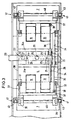
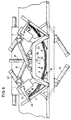
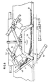
- FIGS. 1 to 4 serve to explain the basic structure of the device according to the invention
- FIGS. 5 to 9 illustrate the method which can be carried out with the device for breaking up the sheet-like material present in stack form.
- Figures 1 to 4 show a table 1, which is constructed symmetrically with respect to the planes 2 and 3 perpendicular to the sheet planes. It has a center table part 4 and two table parts 7 which adjoin directly on the end faces of the center table 4 opposite one another in the longitudinal direction of the table 1 and can be pivoted about axes 8.
- the middle table part 4 is in each case adjacent to the table parts 7 in the area of its support plane, that is to say above, provided with a recess 5, and the respective table part 7 also above and adjacent to the middle table part 4 with a recess 9 (see FIG. 6).
- the respective recess 5 extends approximately over 1/4 the length of the center table part 4 and the respective recess 9 extends over approximately 1/3 the length of the respective pivotable table part 7.
- the respective recess 5 has one an axis 10 pivotable bridge segment 11.
- the thickness of the table parts 7 and the bridge segments 11 and the dimensions of the recesses 5 and 9 are dimensioned such that when the table parts 7 and thus also the bridge segments 11 are pivoted in, the surface of the center table part 4 forms a plane with the upper surfaces of the table parts 7 and bridge segments 11 .
- the bridge segments 11 slide with their free ends 12 in the recesses 9 until they reach the maximum unfolded position of the table parts 7, which is pivoted out by an angle of approximately 55 °, adjacent to the undercut 13 forming the recess 9 in each case Table part 7 come to rest.
- the extent of the respective retracted table part 7 in the longitudinal direction of the table 1 is approximately 60% of half the table length and together with the respective bridge segments 11 is approximately 80% of half the table length.
- the maximum swivel range of the table parts 7 is not limited to the specific swivel value of 55 °, it will usually move in an angular range of 30 to 70 °, preferably 45 to 60 °.
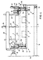
- FIG. 4 illustrates the mounting of the table 1 in a frame 17, which is slidably mounted in the longitudinal direction of the table 1 in an angle stand 18.
- the longitudinal guides of the frame 17 accommodating the table 1 are designated by the reference numbers 19.
- the figure also shows that the width of the table parts 7 extends almost over the entire width of the table 1, and that two bridge segments 11 are arranged side by side, each about 1/4 as wide as the table.
- the frame 17 has a horizontal support 20, which extends perpendicularly to the longitudinal guides 19 to almost the opposite end of the table 1 above it, on which, by means of spaced-apart, vertical guides 21, there extends almost the entire width of the table 1 extending, vertically movable portal frame 22 is guided.
- the portal frame 22 essentially consists of a central carrier 23 arranged below the carrier 20 and two outer carriers 24a and 24b spaced apart from it, wherein the central carrier 23 and the outer carriers 24a and 24b. 24b are connected to each other via two short longitudinal beams 25.
- the two guides 21, which are designed as tubes, are connected to the center support 23 and each penetrate a guide bore (not shown in detail) in the support 20.
- a pneumatic cylinder 26 is also connected to the carrier 20, the piston rod 27 acting on the central carrier 23 in the center between the two guides 21.
- a support frame 28 which is constructed symmetrically to the axis 2 and has a horizontal central section 29 and two leg sections 30a and 30b directed downward at an angle of approximately 120 ° thereto.
- Carriers 32 are mounted in joints 31 in the region of the free ends of the leg sections 30a, 30b, the distance between the joints 31 of the respective support frame 28 corresponding to the distance between the axes 8 of the table 1.
- pneumatic cylinders 34 are pivotally mounted in bearing flanges 33 about bearing points 35, the piston rod 36 of the respective of the two pneumatic cylinders 34 articulately engaging a cross member 37 connecting the two associated supports 32 at point 38.
- the regions 32a facing away from the joint 31 are oriented essentially horizontally.
- a pressure roller 40 being mounted between two associated lugs 39. This extends almost over the entire width of the table 1.
- the pressure rollers 40 are provided with adjustable braking devices, not shown, for example in the form of disc springs, so that they can rotate when a defined torque is exceeded.
- a vertically oriented pneumatic cylinder 43 is pivotally mounted about an axis 42 arranged parallel to the bearing axis 31, the downwardly oriented piston rod 44 of which is in each case outside the contour of the table 1 arranged relief hook 45 takes.
- the respective are corresponding Provide table parts 7 on their broad sides with externally projecting retaining pins 46.
- the relief hooks 45 can enclose the holding pins 46 in a certain operating position with the hook opening directed towards the middle table part 4.
- a bearing plate 47 is connected to the carrier region 32a of the carrier 32 and has a stop pin 48 in the path of movement of the relief hook 45.
- the respective relief hook 45 On the side facing the middle table part 4, the respective relief hook 45 has a bent bevel 49 directed towards the piston rod 44 towards the middle table part 4.
- FIGS. 1 to 4 illustrate the eccentric arrangement of a hold-down device 50 with respect to the longitudinal axis of the table, which can be moved vertically by means of a pneumatic cylinder 51 connected to the central support 23.
- the device Before the table 1 is loaded with a stack 53 formed from individual sheets 52, the device is in the position shown in FIG. 5, that is to say the table parts 7 and the bridge segments 11 are folded in, so that the table 1 has a flat support surface. Furthermore, the support frame 28 is lowered when the supports 32 are pivoted up. By means of a gripper arrangement, not shown, a stack 53 is removed, for example, from an entire stack, also not shown, and placed symmetrically on levels 2 and 3 on table 1 and clamped there after holding down device 50 has been moved down. Then the gripper is out of range again move the table 1.
- the stack 53 lying on the table 1, separated from the entire stack, generally forms a closed block after lying on the stack 1, that is to say the individual sheets 52 cannot be easily moved relative to one another, which is a prerequisite for aligning the stack precisely in a subsequent vibrating table, not shown in detail.
- the pneumatic cylinders 16 are acted upon and cause the table parts 7 and thus also the bridge segments 11 to fold up into the position shown in FIG. In this position, the sheet layers are increasingly displaced from the neutral plane 2 to the edges 54a and 54b, so that the block formation is already eliminated in the displacement area.
- the pressure rollers 40 come into contact with the stack 53 in the area of the stack edges 54a and 54b and the relief hooks 45 engage behind the retaining pins 46.
- the piston rod 44 of the hook-side pneumatic cylinder 43 one becomes via the respective pressure roller 40 predetermined pressure applied to the stack 53 ( Figure 6).
- FIG. 8 shows a section of the method which lends itself particularly to the breaking process shown in FIGS. 5 to 7.
- the table parts 7 and the bridge segments 11 are again pivoted into the extended position shown in FIG. 6, but it must be ensured that only the pressure roller 40 assigned to the stack edge 54a acts on the stack 53.
- the pressure roller 40 assigned to the edge 54a of the stack 53 fixes this stack area, so that the stack 53 is present in the form of a parallelogram when the table parts 7 and the bridge segments 11 are retracted.
- breaking open is expedient if - based on the illustration in FIG.
- the stack 53 is then to be shaken in a shaking station, lying on the right.
- a shaking station lying on the right.
- the stack 53 When loaded only by means of the right pressure roller 40 - as shown in FIG. 9 - there is an opposite shape of the stack 53, with the possibility of a left contact in a subsequent vibrating station.
Landscapes
- Engineering & Computer Science (AREA)
- Mechanical Engineering (AREA)
- Pile Receivers (AREA)
- Sheets, Magazines, And Separation Thereof (AREA)
- Primary Cells (AREA)
- Folding Of Thin Sheet-Like Materials, Special Discharging Devices, And Others (AREA)
- Battery Mounting, Suspending (AREA)
Claims (14)
- Procédé pour rompre une pile (53) formée de produits en feuille, comprenant une table (1) recevant la pile (53), la table (1) ayant au niveau d'une extrémité, une partie de table (7, 11) qui peut se relever par basculement à partir du plan horizontal de la table et un élément de pression (40) associé à cette partie de table (7, 11) au-dessus de cette partie de table (7, 11) et qui peut se rapprocher de celle-ci, caractérisé en ce que la partie de table (7, 11) est relevable et la table (1) comporte à son extrémité opposée à la partie de table relevable (7, 11) une autre partie de table relevable (7, 11), le basculement en retour de la partie de table (7, 11) à laquelle est associé l'élément de pression (40) se faisant avec l'élément de pression (40) agissant sur la partie correspondante de la pile.
- Procédé selon la revendication 1, caractérisé en ce que les parties de table (7, 11) sont basculées en retour, successivement, en direction du plan de la table.
- Procédé selon la revendication 1, caractérisé en ce qu'à l'autre partie de table (7, 11) et au-dessus de celle-ci (7,11) est associé un élément de pression (40) qui peut être rapproché de cette partie de table, et lorsque les éléments de pression (40) agissent, les parties de table (7, 11) sont rabattues simultanément dans le plan de la table, la poussée de chaque élément de pression (40) agissant sur la pile (53) étant dimensionnée pour que les couches de feuilles tournées vers cet élément de pression glissent sous celui-ci avant que l'on arrive à la résistance de rupture de la feuille respective (52).
- Procédé selon l'une des revendications 1 à 3, caractérisé en ce que l'élément de pression (40) respectif agit sur la pile (53) au niveau d'un petit côté de la pile et pendant l'opération, de l'air est soufflé dans la zone des grands côtés de la pile (53) entre les feuilles (52).
- Procédé selon l'une des revendications 1 à 4, caractérisé en ce que la partie de table (7) respective peut être relevée d'un angle de 30° à 70°, de préférence de 45 à 60° hors du plan de la table.
- Procédé selon l'une des revendications 1 à 5, caractérisé par des moyens (50) qui fixent la pile (53) par une liaison de frottement ou de forme sur la pile (53), jusqu'à ce que le ou les éléments de pression (40) soient en appui.
- Dispositif pour la mise en oeuvre du procédé selon l'une des revendications précédentes, comprenant une table (1), avec au niveau de son extrémité une partie de table (7, 11) qui peut être relevée par rapport au plan horizontal de la table ainsi qu'un élément de pression (40) associé à cette partie de table, prévu au-dessus de la partie de table et qui peut se rapprocher de celle-ci, caractérisé en ce que la table (11) comporte à son extrémité opposée à la partie de table relevable (7, 11) une autre partie de table relevable (7, 11) et cette autre partie de table comporte au-dessus d'elle un élément de compression (40) qui peut se rapprocher de celle-ci, les deux parties de table (7, 11) pouvant être basculées autour d'axes de basculement parallèles, par un premier moyen moteur (16) et les éléments de pression (40) peuvent être rapprochés dans la direction de la partie de table (7) par des seconds moyens moteurs (34).
- Dispositif selon la revendication 7, caractérisé par un châssis en portique (22) mobile verticalement, recevant deux supports (32) pivotés par les seconds moyens moteurs (34) pour l'élément de pression (40) monté dans chaque support (32), ainsi que des troisièmes moyens moteurs 43) logés dans chaque support (32) respectif, qui reçoivent les crochets de décharge (45) qui peuvent être mis en coopération avec les ergots de fixation (46) ou moyens analogues prévus dans les parties de table relevable (7).
- Dispositif selon la revendication 7 ou 8, caractérisé en ce que les deux parties de table (7, 11) reçoivent entre elles une partie médiane (4).
- Dispositif selon la revendication 9, caractérisé en ce qu'à chaque partie de table relevable (7) est associé un segment de pont (11) recouvrant partiellement chaque partie de table pivotante (7) et monté pivotant parallèlement à l'axe de pivotement (8) de la partie de table basculante (7), dans celle-ci ou à la partie médiane (4) voisine.
- Dispositif selon l'une des revendications 7 à 10, caractérisé en ce que les moyens moteurs (16, 26, 34, 43, 51) du dispositif sont des vérins pneumatiques ou hydrauliques.
- Dispositif selon l'une des revendications 7 à 11, caractérisé en ce que les éléments de pression sont des galets de pression (40) qui s'étendent en particulier sur tout le petit côté de la table (1).
- Dispositif selon la revendication 12, caractérisé en ce que les éléments de pression (40) sont munis de dispositifs de freinage en particulier de dispositifs de freinage à couple de freinage réglable.
- Dispositif selon l'une des revendications 7 à 13, caractérisé en ce qu'il est monté mobile horizontalement dans un bâti (17).
Applications Claiming Priority (2)
| Application Number | Priority Date | Filing Date | Title |
|---|---|---|---|
| DE3933625A DE3933625C1 (fr) | 1989-10-07 | 1989-10-07 | |
| DE3933625 | 1989-10-07 |
Publications (3)
| Publication Number | Publication Date |
|---|---|
| EP0422563A2 EP0422563A2 (fr) | 1991-04-17 |
| EP0422563A3 EP0422563A3 (en) | 1992-02-26 |
| EP0422563B1 true EP0422563B1 (fr) | 1995-07-26 |
Family
ID=6391082
Family Applications (1)
| Application Number | Title | Priority Date | Filing Date |
|---|---|---|---|
| EP90119268A Expired - Lifetime EP0422563B1 (fr) | 1989-10-07 | 1990-10-08 | Procédé pour rompre une pile des feuilles et dispositif pour mettre en oeuvre le procédé |
Country Status (5)
| Country | Link |
|---|---|
| US (1) | US5082271A (fr) |
| EP (1) | EP0422563B1 (fr) |
| JP (1) | JPH0825659B2 (fr) |
| DE (2) | DE3933625C1 (fr) |
| ES (1) | ES2076273T3 (fr) |
Families Citing this family (7)
| Publication number | Priority date | Publication date | Assignee | Title |
|---|---|---|---|---|
| ES2068509T3 (es) * | 1990-06-01 | 1995-04-16 | De La Rue Syst | Metodo de deteccion de hojas en una pila. |
| US5288065A (en) * | 1992-03-06 | 1994-02-22 | De La Rue Giori S.A. | Method for separating sheets of paper stacked in reams and device for implementing this method |
| US20030060264A1 (en) * | 2001-09-21 | 2003-03-27 | Chilton Ward W. | Gaming device providing tournament entries |
| US7597319B2 (en) * | 2005-05-20 | 2009-10-06 | Hewlett-Packard Development Company, L.P. | Sheet handling using a ramp and grippers on an endless belt |
| ES2762102T3 (es) | 2016-02-10 | 2020-05-22 | Bobst Grenchen Ag | Sistema de manipulación para manipular elementos planos apilables |
| CN106429547A (zh) * | 2016-11-25 | 2017-02-22 | 湖州佳宁印刷有限公司 | 能自动疏纸和码齐的上纸台 |
| CN106429545A (zh) * | 2016-11-25 | 2017-02-22 | 湖州佳宁印刷有限公司 | 一种能自动疏纸和码齐的上纸台 |
Family Cites Families (19)
| Publication number | Priority date | Publication date | Assignee | Title |
|---|---|---|---|---|
| DE123210C (fr) * | ||||
| US802679A (en) * | 1905-03-27 | 1905-10-24 | Felix A Venney | Paper-separator. |
| US1147482A (en) * | 1914-02-20 | 1915-07-20 | Carey A Cheshire | Base-plate for feeding mechanisms. |
| DE576716C (de) * | 1928-07-10 | 1933-05-17 | Faber & Schleicher A G | Vorrichtung zum Staffeln eines Bogenstapels unter abwechselndem Auf- und Abbiegen und Festhalten des Stapels |
| US2991075A (en) * | 1958-12-30 | 1961-07-04 | Ibm | Bed plate for a card feed |
| US3720407A (en) * | 1971-12-30 | 1973-03-13 | C Woodward | Automatic sheet winding apparatus and method of winding a skid of sheet material |
| DE2639677C2 (de) * | 1976-09-03 | 1986-01-30 | Maschinenbau Oppenweiler Gmbh, 7155 Oppenweiler | Verfahren und Vorrichtung zum Schuppen eines Bogenstapels |
| DE2649959C2 (de) * | 1976-10-30 | 1985-09-12 | Karl Mohr | Vorrichtung zur Übergabe eines Teilstapels zu beschneidenden Gutes von einem Gesamtstapel in eine Rüttelstation |
| DE2723162A1 (de) * | 1977-05-23 | 1978-11-30 | Mohr | Vorrichtung zur uebergabe eines teilstapels bedruckter boegen von einem gesamtstapel in eine ruettelstation |
| CH617409A5 (en) * | 1977-06-01 | 1980-05-30 | Willi Schneider | System for jogging material sheets to form a stack |
| JPS55119641A (en) * | 1979-03-09 | 1980-09-13 | Toshiba Corp | Paper sheet delivery device |
| DE3060511D1 (en) * | 1979-03-09 | 1982-07-29 | Tokyo Shibaura Electric Co | Thin sheet feeding apparatus |
| JPS567846A (en) * | 1979-06-29 | 1981-01-27 | Ibm | Separator for stackklike sheet |
| SU1003975A1 (ru) * | 1981-09-01 | 1983-03-15 | ла витель В. И. Дрыгант | Способ разделени стопы листовых изделий |
| SU1003976A1 (ru) * | 1981-09-09 | 1983-03-15 | за вители П ЛУ;-,,,., .., л Н.. Барановский и Г. А. .; / | Способ разделени стопы листовых изделий |
| DE3220917C2 (de) * | 1982-06-03 | 1984-10-18 | Gerhard Zöll Maschinenbau, 6238 Hofheim | Verfahren zum Abteilen von Teilstapeln von einem Gesamtstapel und zum Ablegen jedes Teilstapels in schuppenförmiger Lage |
| US4482146A (en) * | 1982-11-24 | 1984-11-13 | E. I. Du Pont De Nemours And Company | Dispenser of single film sheets |
| JPS6034427U (ja) * | 1983-08-17 | 1985-03-09 | 凸版印刷株式会社 | カ−トンブランクス処理装置 |
| JPS6090223U (ja) * | 1983-11-22 | 1985-06-20 | 石川島播磨重工業株式会社 | 貯蔵ヤ−ド用機械 |
-
1989
- 1989-10-07 DE DE3933625A patent/DE3933625C1/de not_active Expired - Lifetime
-
1990
- 1990-10-03 US US07/592,238 patent/US5082271A/en not_active Expired - Fee Related
- 1990-10-03 JP JP2263978A patent/JPH0825659B2/ja not_active Expired - Lifetime
- 1990-10-08 DE DE59009433T patent/DE59009433D1/de not_active Expired - Fee Related
- 1990-10-08 EP EP90119268A patent/EP0422563B1/fr not_active Expired - Lifetime
- 1990-10-08 ES ES90119268T patent/ES2076273T3/es not_active Expired - Lifetime
Also Published As
| Publication number | Publication date |
|---|---|
| DE3933625C1 (fr) | 1991-03-14 |
| EP0422563A3 (en) | 1992-02-26 |
| JPH03133853A (ja) | 1991-06-07 |
| ES2076273T3 (es) | 1995-11-01 |
| US5082271A (en) | 1992-01-21 |
| JPH0825659B2 (ja) | 1996-03-13 |
| DE59009433D1 (de) | 1995-08-31 |
| EP0422563A2 (fr) | 1991-04-17 |
Similar Documents
| Publication | Publication Date | Title |
|---|---|---|
| EP0422562B1 (fr) | Dispositif pour transporter une section de pile de feuilles d'une pile à une station de traitement ultérieur | |
| EP0429941B1 (fr) | Dispositif pour couper des feuilles empilées | |
| DE4013352C2 (fr) | ||
| DE19901496C1 (de) | Klemmgreifer für von oben zu greifende Lasten | |
| DE2924017C2 (de) | Vorrichtung zum Annähen eines ringförmigen elastischen Bandes an ein schlauchförmiges Werkstück auf einer Nähmaschine | |
| EP0181993B1 (fr) | Dispositif pour saisir et déposer des produits divers | |
| DE3320731A1 (de) | Verfahren und vorrichtung zum laengs- und querfalten eines blattes | |
| EP0422563B1 (fr) | Procédé pour rompre une pile des feuilles et dispositif pour mettre en oeuvre le procédé | |
| EP2017177B1 (fr) | Pince aspirante ou grappin à fourches pour redresser un carton | |
| EP0436506A1 (fr) | Dispositif pour aligner des piles | |
| DE2942883C2 (de) | Vorrichtung zum Verschließen des Bodens einer rechteckigen aufgerichteten Faltschachtel | |
| EP0096398A1 (fr) | Dispositif pour transporter des piles de sacs en papier | |
| EP0732290B1 (fr) | Dispositif pour transférer et empiler des piles coupées de produits en forme de feuilles | |
| DE3814177C2 (fr) | ||
| EP0564971B1 (fr) | Dispositif et procédé pour fabriquer une pile d'articles | |
| DE19914580A1 (de) | Verfahren zum Handhaben von Stapeln von Papier, Pappe o. dgl. an einer Schneidmaschine | |
| DE2855138C2 (de) | Vorrichtung zum Abschneiden eines Haltebandes | |
| EP0540896A1 (fr) | Machine à enrouler pour enrouler une bande, notamment une bande de papier | |
| CH617409A5 (en) | System for jogging material sheets to form a stack | |
| EP1415920A1 (fr) | Dispositif pour manipuler et aplatir un carton contenant du tabac | |
| DD280731A1 (de) | Vorrichtung zum auffalten vorgefertigter kartonzuschnitte | |
| DE4327450C1 (de) | Verfahren und Vorrichtung zum Überziehen einer Stretchfolienhaube über einen Gutstapel | |
| EP0043517A1 (fr) | Dispositif pour enfiler un capot de feuille rétractable sur une pile d'articles | |
| DE3143011A1 (de) | Steuerkurvenbetaetigte greifvorrichtung fuer bedruckte papierbahnen | |
| DE10053887A1 (de) | Taschen-Transportsystem für Druckprodukte |
Legal Events
| Date | Code | Title | Description |
|---|---|---|---|
| PUAI | Public reference made under article 153(3) epc to a published international application that has entered the european phase |
Free format text: ORIGINAL CODE: 0009012 |
|
| 17P | Request for examination filed |
Effective date: 19901207 |
|
| AK | Designated contracting states |
Kind code of ref document: A2 Designated state(s): BE CH DE ES FR GB IT LI LU NL SE |
|
| PUAL | Search report despatched |
Free format text: ORIGINAL CODE: 0009013 |
|
| AK | Designated contracting states |
Kind code of ref document: A3 Designated state(s): BE CH DE ES FR GB IT LI LU NL SE |
|
| RHK1 | Main classification (correction) |
Ipc: B65H 3/60 |
|
| 17Q | First examination report despatched |
Effective date: 19940214 |
|
| GRAA | (expected) grant |
Free format text: ORIGINAL CODE: 0009210 |
|
| AK | Designated contracting states |
Kind code of ref document: B1 Designated state(s): BE CH DE ES FR GB IT LI LU NL SE |
|
| PG25 | Lapsed in a contracting state [announced via postgrant information from national office to epo] |
Ref country code: BE Effective date: 19950726 |
|
| REF | Corresponds to: |
Ref document number: 59009433 Country of ref document: DE Date of ref document: 19950831 |
|
| ITF | It: translation for a ep patent filed |
Owner name: MODIANO & ASSOCIATI S.R.L. |
|
| ET | Fr: translation filed | ||
| PG25 | Lapsed in a contracting state [announced via postgrant information from national office to epo] |
Ref country code: LU Free format text: LAPSE BECAUSE OF NON-PAYMENT OF DUE FEES Effective date: 19951031 |
|
| REG | Reference to a national code |
Ref country code: ES Ref legal event code: FG2A Ref document number: 2076273 Country of ref document: ES Kind code of ref document: T3 |
|
| GBT | Gb: translation of ep patent filed (gb section 77(6)(a)/1977) |
Effective date: 19951009 |
|
| PLBE | No opposition filed within time limit |
Free format text: ORIGINAL CODE: 0009261 |
|
| STAA | Information on the status of an ep patent application or granted ep patent |
Free format text: STATUS: NO OPPOSITION FILED WITHIN TIME LIMIT |
|
| 26N | No opposition filed | ||
| PGFP | Annual fee paid to national office [announced via postgrant information from national office to epo] |
Ref country code: GB Payment date: 19960916 Year of fee payment: 7 |
|
| PGFP | Annual fee paid to national office [announced via postgrant information from national office to epo] |
Ref country code: FR Payment date: 19960920 Year of fee payment: 7 Ref country code: CH Payment date: 19960920 Year of fee payment: 7 |
|
| PGFP | Annual fee paid to national office [announced via postgrant information from national office to epo] |
Ref country code: SE Payment date: 19960923 Year of fee payment: 7 |
|
| PGFP | Annual fee paid to national office [announced via postgrant information from national office to epo] |
Ref country code: NL Payment date: 19960930 Year of fee payment: 7 |
|
| PGFP | Annual fee paid to national office [announced via postgrant information from national office to epo] |
Ref country code: ES Payment date: 19961018 Year of fee payment: 7 |
|
| PGFP | Annual fee paid to national office [announced via postgrant information from national office to epo] |
Ref country code: DE Payment date: 19961227 Year of fee payment: 7 |
|
| PG25 | Lapsed in a contracting state [announced via postgrant information from national office to epo] |
Ref country code: GB Free format text: LAPSE BECAUSE OF NON-PAYMENT OF DUE FEES Effective date: 19971008 |
|
| PG25 | Lapsed in a contracting state [announced via postgrant information from national office to epo] |
Ref country code: SE Free format text: LAPSE BECAUSE OF NON-PAYMENT OF DUE FEES Effective date: 19971009 Ref country code: ES Free format text: LAPSE BECAUSE OF EXPIRATION OF PROTECTION Effective date: 19971009 |
|
| PG25 | Lapsed in a contracting state [announced via postgrant information from national office to epo] |
Ref country code: LI Free format text: LAPSE BECAUSE OF NON-PAYMENT OF DUE FEES Effective date: 19971031 Ref country code: FR Free format text: THE PATENT HAS BEEN ANNULLED BY A DECISION OF A NATIONAL AUTHORITY Effective date: 19971031 Ref country code: CH Free format text: LAPSE BECAUSE OF NON-PAYMENT OF DUE FEES Effective date: 19971031 |
|
| PG25 | Lapsed in a contracting state [announced via postgrant information from national office to epo] |
Ref country code: NL Free format text: LAPSE BECAUSE OF NON-PAYMENT OF DUE FEES Effective date: 19980501 |
|
| GBPC | Gb: european patent ceased through non-payment of renewal fee |
Effective date: 19971008 |
|
| REG | Reference to a national code |
Ref country code: CH Ref legal event code: PL |
|
| NLV4 | Nl: lapsed or anulled due to non-payment of the annual fee |
Effective date: 19980501 |
|
| PG25 | Lapsed in a contracting state [announced via postgrant information from national office to epo] |
Ref country code: DE Free format text: LAPSE BECAUSE OF NON-PAYMENT OF DUE FEES Effective date: 19980701 |
|
| EUG | Se: european patent has lapsed |
Ref document number: 90119268.2 |
|
| REG | Reference to a national code |
Ref country code: FR Ref legal event code: ST |
|
| REG | Reference to a national code |
Ref country code: ES Ref legal event code: FD2A Effective date: 20010201 |
|
| PG25 | Lapsed in a contracting state [announced via postgrant information from national office to epo] |
Ref country code: IT Free format text: LAPSE BECAUSE OF NON-PAYMENT OF DUE FEES;WARNING: LAPSES OF ITALIAN PATENTS WITH EFFECTIVE DATE BEFORE 2007 MAY HAVE OCCURRED AT ANY TIME BEFORE 2007. THE CORRECT EFFECTIVE DATE MAY BE DIFFERENT FROM THE ONE RECORDED. Effective date: 20051008 |