EP0421791B1 - Farbsprühsystem - Google Patents
Farbsprühsystem Download PDFInfo
- Publication number
- EP0421791B1 EP0421791B1 EP90310886A EP90310886A EP0421791B1 EP 0421791 B1 EP0421791 B1 EP 0421791B1 EP 90310886 A EP90310886 A EP 90310886A EP 90310886 A EP90310886 A EP 90310886A EP 0421791 B1 EP0421791 B1 EP 0421791B1
- Authority
- EP
- European Patent Office
- Prior art keywords
- machines
- spray painting
- work
- upper rail
- rail
- Prior art date
- Legal status (The legal status is an assumption and is not a legal conclusion. Google has not performed a legal analysis and makes no representation as to the accuracy of the status listed.)
- Expired - Lifetime
Links
Images


Classifications
-
- B—PERFORMING OPERATIONS; TRANSPORTING
- B05—SPRAYING OR ATOMISING IN GENERAL; APPLYING FLUENT MATERIALS TO SURFACES, IN GENERAL
- B05B—SPRAYING APPARATUS; ATOMISING APPARATUS; NOZZLES
- B05B13/00—Machines or plants for applying liquids or other fluent materials to surfaces of objects or other work by spraying, not covered by groups B05B1/00 - B05B11/00
- B05B13/02—Means for supporting work; Arrangement or mounting of spray heads; Adaptation or arrangement of means for feeding work
- B05B13/04—Means for supporting work; Arrangement or mounting of spray heads; Adaptation or arrangement of means for feeding work the spray heads being moved during spraying operation
- B05B13/0447—Installation or apparatus for applying liquid or other fluent material to conveyed separate articles
- B05B13/0452—Installation or apparatus for applying liquid or other fluent material to conveyed separate articles the objects being vehicle components, e.g. vehicle bodies
-
- B—PERFORMING OPERATIONS; TRANSPORTING
- B05—SPRAYING OR ATOMISING IN GENERAL; APPLYING FLUENT MATERIALS TO SURFACES, IN GENERAL
- B05B—SPRAYING APPARATUS; ATOMISING APPARATUS; NOZZLES
- B05B14/00—Arrangements for collecting, re-using or eliminating excess spraying material
- B05B14/40—Arrangements for collecting, re-using or eliminating excess spraying material for use in spray booths
- B05B14/46—Arrangements for collecting, re-using or eliminating excess spraying material for use in spray booths by washing the air charged with excess material
- B05B14/468—Arrangements for collecting, re-using or eliminating excess spraying material for use in spray booths by washing the air charged with excess material with scrubbing means arranged below the booth floor
-
- B—PERFORMING OPERATIONS; TRANSPORTING
- B05—SPRAYING OR ATOMISING IN GENERAL; APPLYING FLUENT MATERIALS TO SURFACES, IN GENERAL
- B05B—SPRAYING APPARATUS; ATOMISING APPARATUS; NOZZLES
- B05B16/00—Spray booths
- B05B16/40—Construction elements specially adapted therefor, e.g. floors, walls or ceilings
-
- B—PERFORMING OPERATIONS; TRANSPORTING
- B05—SPRAYING OR ATOMISING IN GENERAL; APPLYING FLUENT MATERIALS TO SURFACES, IN GENERAL
- B05B—SPRAYING APPARATUS; ATOMISING APPARATUS; NOZZLES
- B05B16/00—Spray booths
- B05B16/90—Spray booths comprising conveying means for moving objects or other work to be sprayed in and out of the booth, e.g. through the booth
- B05B16/95—Spray booths comprising conveying means for moving objects or other work to be sprayed in and out of the booth, e.g. through the booth the objects or other work to be sprayed lying on, or being held above the conveying means, i.e. not hanging from the conveying means
Definitions
- the present invention relates to a spray painting system, and more particularly to a spray painting system of a continous assembly line, the system including a plurality of work machines for spray painting disposed side by side along a direction for conveying a work object inside a spray painting booth.
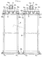
- each of a plurality of work machines 6 is arranged movable within a predetermined distance l (usually about 1 m) in the object-conveying direction on a mounting frame fixed on a floor surface of the booth.
- l usually about 1 m
- a paint robot 18 is disclosed displaceably mounted on guide rails 20 with the working area of the spray booth lower than the top of vehicle body 10 and accordingly is subject to a substantial spray mist environment.
- a single rail 20 on one side is illustrated having a carriage 32 mounted on edge portions between which a rack 26 is provided.
- GB-A-2098578 an industrial production system are disclosed a plurality of robotic operating arm structures 2 mounted on a single I sectioned rail 6 by means of carriages 8 with rail 6 being within the working environment space.
- Support rollers 40 roll on the top surface of rail 6 and guide rollers 41 roll on the vertical sides of rail 6 directly beneath rollers 40.
- Rail 6 is mounted along the top side edge of bench 7 which also supports workpieces.
- a spray painting system having a plurality of work machines disposed side by side along the direction of conveyance of a work object to be sprayed inside a spray painting booth and having an upper rail and a lower rail for guiding the work machines to move along said conveying direction, with each of the machines running on said upper rail characterised by said upper rail being arranged in a region outwardly of the working area of said spray painting booth and positioned higher than at least said work object; said upper rail supporting the work machines so as to receive all the load therefrom, and said lower rail guiding said work machines without receiving any load from said work machines.
- the rails guide the movement of the machines along path of travel of the work objects with the machines supported on respective frames and each machine being detachably supported on the respective frame.
- the same upper and lower rails guide the movement of a plurality of work machines in the object-conveying direction with the machines running on the upper rail.
- the system of the invention can readily cope with frequent position adjustment operations of the machines as required and also substantial changes in the work conditions without requiring total relocation of the machines. Consequently, the spray painting system of the present invention has achieved significant reduction in the shutdown period of the production line which used to be required for troublesome position adjustment or total relocation of the work machines, thus improving the entire operation efficiency of the production line including this system as well as other lines associated therewith.
- the system can change the disposing order of the work machines in the object-conveying direction.
- FIG. 1 through 4 illustrate a preferred embodiment of a spray painting system according to the present invention.
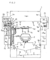
- a tunnel-like spray painting booth 1 accommodates a conveyor device 1 for conveying an object 2 (an automobile body in the instant embodiment), an overhead outlet vent 4 for downwardly discharching a ventilation air and a demister 5 for eliminating spray mist contained in exhaust air by traping the mist in cleaning water.
- a purality of work machines 6 for the spray painting with the machines being disposed side by side along a direction of conveying the object 2 inside the booth.
- the work machines 6 comprise various kinds such as one-hand robbot 6a for opening and closing doors of the object 2, i.e. automobile body, a further one-hand robbot 6b for controlling a spray gun 7a to spray-paint interior surfaces of the object 2, a side-face spraying machine 6c for vertically moving a spray gun 7b to spray-paint side outer surfaces of the object 2, an upper-face spraying machine 6d for controlling rotary, reciprocating and vertical linear movements of an arm 7d equipped with a spray gun 7c so as to spray-paint upper surfaces of the object, and a touchup spray painting, one-hand robbot 6e for controlling a further spray gun 6e to effect a touchup spray-paint operation on the object.
- one-hand robbot 6a for opening and closing doors of the object 2, i.e. automobile body
- a further one-hand robbot 6b for controlling a spray gun 7a to spray-paint interior surfaces of the object 2
- each frame 8 has a first roller 10a for rolling on an upper face of the upper rail 9a with the weight of the frame 8 being supported by the rail 9a, a pair of second rollers 10b lie astride the upper rail 9a and a pair of third rollers 10c lie astride the lower rail 9b.
- the frame 8 also has a pair of free sprockets 12a engageable with the chain 11, a drive sprocket 12b which comes into engagement with an inner side of the chain 11 which is formed like a reversed letter U-shaped as being entrained about the two free sprockets 12a, and a motor 14 for driving the drive sprocket 12b via a reduction mechanism 13.
- the frame 8 i.e. the work machine 6 mounted on this frame
- the frame 8 is self-movable along the object-conveying direction within the range determined by the length of the upper and lower rails 9a and 9b, while the chain 11 acting as resistance againt react ion force associated with the movement of the frame 4.
- the setting position of the work machine 6 has be changed to cope with various changes in the operating conditions such as in the type of paint, the spray guns 7a, 7b, 7c and 7e and/or in the shape of the object 2, i.e. the automobile body
- the position adjustment is readily possible by selectively and independently causing the machines 6 to self-move along the object-conveying direction.
- an operator box 15 having a length extending over the entire length of the rails 9a and 9b is integrally attached to the booth side wall 1a; and the booth side wall 1a has a window 16 for allowing an operator inside an operator chamber 15a of the box 15 to inspect and watch the spray painting operation taking place inside the booth.
- a partition 11 is provided for forming an upper section 15b separately from the operator chamber 15a.
- the upper section 15b accommodates paint hose-cable means 18 such as paint hoses, electric cables and pressure-air hoses for feeding paint, electricity and pressure air to the respective work machines 6; flexible means 19 such as flexible cable racks for allowing movements of the work machines 6 along the conveying direction and further the upper rail 9a and the chain 11.
- the upper section 15b further accommodates a shaft 14a for operatively connecting the motor 14 and the drive sprocket 12b and an opening S for inserting the hose-cable means 18 therethrough.
- control panel 22 for remote-controlling the work machines 6.
- control panel means 24 such as electric control panels and pressure-air control panels.
- the operator chamber 15a is connected with a duct 21 having a dumper 20 for forcibly introducing ventilatin air from a air feed chamber 4a through the overhead outlet vent 4 into the chamber 15a.
- Numeral 25 denotes a grating floor used for e.g. a system maintenance operation.
- This grating floor 25 is provided only at a certain region inside the booth along the object-conveying direction.
- the machine 6 to be maintained is driven to self-move to the region of the grating floor 25.
- the grating floor 25 is provided only at a certain region inside the booth, cleaning operation of this grating floor 25 to eliminate excess paint adhered thereto is required less frequently than the conventional system in which the grating floor is provide over the entire booth floor.
- this grating floor 25 movable in the object-conveying direction.
- the setting location of the grating floor 25 can be changed in accordance with the necessity and convenience.
- the types of the work implements used for spray painting operation are not limited to those described in the foregoing embodiment.
- the object 2, in place of the automobile body can be any kind such as a casing of a home electric appliance or a train body and so on.
Landscapes
- Spray Control Apparatus (AREA)
- Details Or Accessories Of Spraying Plant Or Apparatus (AREA)
Claims (4)
- Farbsprühsystem mit einer Vielzahl von Arbeitsmaschinen (6), die nebeneinander entlang der Förderrichtung eines Arbeitsgegenstandes (2) angeordnet sind, der innerhalb einer Farbsprühkabine (1) besprüht wird, und mit einer oberen Schiene (9a) und einer unteren Schiene (9b) zur Führung der Arbeitsmaschinen entlang dieser Förderrichtung, wobei jede der Arbeitsmaschinen (6) auf der oberen Schiene (9a) läuft,
dadurch gekennzeichnet, daß die obere Schiene (9a) außerhalb des Arbeitsbereichs der Farbsprühkabine und oberhalb zumindest des Arbeitsgegenstandes (2) angeordnet ist, wobei die obere Schiene (9a) die Arbeitsmaschinen (6) in dem Sinne aufnimmt, als sie deren gesamtes Gewicht trägt, und die untere Schiene (9b) zur Führung der Arbeitsmaschinen (6) dient, ohne von diesen gewichtsbelastet zu sein. - Farbsprühsystem nach Anspruch 1, dadurch gekennzeichnet, daß die Schienen (9a,9b) die Arbeitsmaschinen (6) in der Förderrichtung des Arbeitsobjektes (2) führen, wobei die Arbeitsmaschinen (6) jeweils von Rahmen (8) aufgenommen werden, in denen sie abnehmbar gehalten sind.
- Farbsprühsystem nach Anspruch 2, dadurch gekennzeichnet, daß der Rahmen (8) eine erste Rolle (10a) zum Abrollen auf der oberen Seite der oberen Schiene (9a) beinhaltet, wobei das Gewicht des Rahmens (8) von der oberen Schiene (9a) aufgenommen wird, sowie ein Paar von zweiten Rollen (10b), die beidseitig die obere Schiene (9a) beaufschlagen und ein Paar von dritten Rollen (10c), die beidseitig die untere Schiene (9b) beaufschlagen.
- Farbsprühsystem nach Anspruch 3, dadurch gekennzeichnet, daß der Rahmen (8) mittels einer Kette (11) angetrieben wird, die entlang der oberen Schiene (9a) verläuft.
Applications Claiming Priority (2)
| Application Number | Priority Date | Filing Date | Title |
|---|---|---|---|
| JP260940/89 | 1989-10-05 | ||
| JP1260940A JPH03123652A (ja) | 1989-10-05 | 1989-10-05 | 塗装設備 |
Publications (3)
| Publication Number | Publication Date |
|---|---|
| EP0421791A2 EP0421791A2 (de) | 1991-04-10 |
| EP0421791A3 EP0421791A3 (en) | 1991-09-18 |
| EP0421791B1 true EP0421791B1 (de) | 1993-12-22 |
Family
ID=17354892
Family Applications (1)
| Application Number | Title | Priority Date | Filing Date |
|---|---|---|---|
| EP90310886A Expired - Lifetime EP0421791B1 (de) | 1989-10-05 | 1990-10-04 | Farbsprühsystem |
Country Status (5)
| Country | Link |
|---|---|
| EP (1) | EP0421791B1 (de) |
| JP (1) | JPH03123652A (de) |
| CA (1) | CA2026931C (de) |
| DE (1) | DE69005404T2 (de) |
| ES (1) | ES2049426T3 (de) |
Families Citing this family (9)
| Publication number | Priority date | Publication date | Assignee | Title |
|---|---|---|---|---|
| DE4114762A1 (de) * | 1991-05-06 | 1992-11-19 | Eisenmann Kg Maschbau | Lackierstrasse, beispielsweise fuer automobilkarosserien |
| JP2756482B2 (ja) * | 1995-05-31 | 1998-05-25 | 川崎重工業株式会社 | 自動車塗装ラインにおけるロボットの配置方法および配置構造 |
| FR2777483A1 (fr) * | 1998-04-15 | 1999-10-22 | Sames Sa | Procede et installation de projection de produit de revetement |
| GB2486705B (en) * | 2010-12-23 | 2013-03-13 | Spraybooth Technology Ltd | Spray booths |
| DE102011121343A1 (de) | 2011-12-16 | 2013-06-20 | Dürr Systems GmbH | Beschichtungsanlage und entsprechendes Betriebsverfahren |
| DE102019215079A1 (de) * | 2019-09-30 | 2021-04-01 | Dürr Systems Ag | Behandlungsanlage und Behandlungsverfahren |
| US20230338980A1 (en) | 2019-09-30 | 2023-10-26 | Dürr Systems Ag | Treatment system and treatment method |
| CN113457897B (zh) * | 2021-07-07 | 2022-07-12 | 成都天码行空机器人研究有限公司 | 一种用于汽车零部件的连续喷涂线及使用方法 |
| CN114054278B (zh) * | 2021-12-09 | 2022-12-16 | 江苏鑫时创铝幕墙制造有限公司 | 一种隔热纳米自洁幕墙铝单板表面处理装置 |
Family Cites Families (5)
| Publication number | Priority date | Publication date | Assignee | Title |
|---|---|---|---|---|
| US4342535A (en) * | 1980-08-14 | 1982-08-03 | General Motors Corporation | Door-opener apparatus |
| IT1144708B (it) * | 1981-05-15 | 1986-10-29 | Dea Spa | Sistema di produzione industriale servito da una pluralita di bracci operativi e controllato da un sistema a calcolatore |
| IT1153412B (it) * | 1982-01-15 | 1987-01-14 | Basfer Srl | Procedimento per la verniciatura automatica di oggetti avanzanti lungo una linea di lavorazione e apparecchiatura per l'attuazione del medesimo procedimento |
| US4721630A (en) * | 1985-07-31 | 1988-01-26 | Honda Giken Kogyo Kabushiki Kaisha | Painting process for inner panel region of motorcar vehicle body and apparatus therefor |
| US4630567A (en) * | 1985-08-28 | 1986-12-23 | Gmf Robotics Corporation | Spray paint system including paint booth, paint robot apparatus movable therein and rail mechanism for supporting the apparatus thereout |
-
1989
- 1989-10-05 JP JP1260940A patent/JPH03123652A/ja active Pending
-
1990
- 1990-10-04 EP EP90310886A patent/EP0421791B1/de not_active Expired - Lifetime
- 1990-10-04 DE DE69005404T patent/DE69005404T2/de not_active Expired - Fee Related
- 1990-10-04 CA CA002026931A patent/CA2026931C/en not_active Expired - Fee Related
- 1990-10-04 ES ES90310886T patent/ES2049426T3/es not_active Expired - Lifetime
Also Published As
| Publication number | Publication date |
|---|---|
| ES2049426T3 (es) | 1994-04-16 |
| JPH03123652A (ja) | 1991-05-27 |
| CA2026931C (en) | 1997-10-14 |
| CA2026931A1 (en) | 1991-04-06 |
| EP0421791A3 (en) | 1991-09-18 |
| DE69005404T2 (de) | 1994-07-14 |
| DE69005404D1 (de) | 1994-02-03 |
| EP0421791A2 (de) | 1991-04-10 |
Similar Documents
| Publication | Publication Date | Title |
|---|---|---|
| EP0216482B1 (de) | Spritzlackiersystem mit Spritzkabine, darin beweglichem Lackierroboter und einem Schienenmechanismus zur Unterstützung der Apparatur | |
| US7650852B2 (en) | Modular painting apparatus | |
| EP0421791B1 (de) | Farbsprühsystem | |
| CA1331085C (en) | Method of installing painting system and painting-machine control unit for use in painting booth | |
| EP2359939B1 (de) | Lackieranlage | |
| CN109070126B (zh) | 用于制造车辆的方法和制造设备和用于车辆车身的表面处理的表面处理设备 | |
| CA2672156C (en) | Coating plant and method for the series coating of workpieces | |
| US6776843B2 (en) | Sprayer device for a motor vehicle body paint spray booth | |
| US5336321A (en) | Paint apparatus having two robots | |
| US4864965A (en) | Automatic painting apparatus | |
| EP0429289B1 (de) | Automatische Farbspritzmaschine | |
| CN113272074A (zh) | 表面处理设备和用于车辆车体的表面处理方法 | |
| CN111719826A (zh) | 一种建筑墙面自动喷漆机器人 | |
| JPH04290570A (ja) | 垂直レシプロ塗装装置 | |
| CN109986166A (zh) | 自动化弧焊工作站 | |
| EP0165627B1 (de) | Robotersystem mit auf Schienen zu bewegendem Wagen | |
| CN210207360U (zh) | 一种卷帘门生产用喷漆装置 | |
| US8015938B2 (en) | Coating zone and coating plant | |
| US8104131B2 (en) | Rollover wash unit for a vehicle wash system | |
| KR0116881Y1 (ko) | 구동부 하나로 동시 상하작동이 가능한 제품도장 스프레이건의수직왕복장치 | |
| JPH05317762A (ja) | 塗装用ロボット装置 | |
| JP3527383B2 (ja) | 塗装ブース | |
| EP3009195B1 (de) | Lackieranlage für karosseriewerkstätten | |
| CN120362761B (zh) | 一种多工位带除尘功能的激光加工设备及激光加工产线 | |
| CN221210802U (zh) | 一种数控机床用导向输送装置 |
Legal Events
| Date | Code | Title | Description |
|---|---|---|---|
| PUAI | Public reference made under article 153(3) epc to a published international application that has entered the european phase |
Free format text: ORIGINAL CODE: 0009012 |
|
| 17P | Request for examination filed |
Effective date: 19901025 |
|
| AK | Designated contracting states |
Kind code of ref document: A2 Designated state(s): DE ES FR GB |
|
| PUAL | Search report despatched |
Free format text: ORIGINAL CODE: 0009013 |
|
| AK | Designated contracting states |
Kind code of ref document: A3 Designated state(s): DE ES FR GB |
|
| 17Q | First examination report despatched |
Effective date: 19920911 |
|
| GRAA | (expected) grant |
Free format text: ORIGINAL CODE: 0009210 |
|
| AK | Designated contracting states |
Kind code of ref document: B1 Designated state(s): DE ES FR GB |
|
| REF | Corresponds to: |
Ref document number: 69005404 Country of ref document: DE Date of ref document: 19940203 |
|
| ET | Fr: translation filed | ||
| REG | Reference to a national code |
Ref country code: ES Ref legal event code: FG2A Ref document number: 2049426 Country of ref document: ES Kind code of ref document: T3 |
|
| PLBE | No opposition filed within time limit |
Free format text: ORIGINAL CODE: 0009261 |
|
| STAA | Information on the status of an ep patent application or granted ep patent |
Free format text: STATUS: NO OPPOSITION FILED WITHIN TIME LIMIT |
|
| 26N | No opposition filed | ||
| PGFP | Annual fee paid to national office [announced via postgrant information from national office to epo] |
Ref country code: FR Payment date: 19970929 Year of fee payment: 8 |
|
| PGFP | Annual fee paid to national office [announced via postgrant information from national office to epo] |
Ref country code: GB Payment date: 19981002 Year of fee payment: 9 |
|
| PGFP | Annual fee paid to national office [announced via postgrant information from national office to epo] |
Ref country code: ES Payment date: 19981006 Year of fee payment: 9 |
|
| PG25 | Lapsed in a contracting state [announced via postgrant information from national office to epo] |
Ref country code: FR Free format text: LAPSE BECAUSE OF NON-PAYMENT OF DUE FEES Effective date: 19990630 |
|
| REG | Reference to a national code |
Ref country code: FR Ref legal event code: ST |
|
| PG25 | Lapsed in a contracting state [announced via postgrant information from national office to epo] |
Ref country code: GB Free format text: LAPSE BECAUSE OF NON-PAYMENT OF DUE FEES Effective date: 19991004 |
|
| PG25 | Lapsed in a contracting state [announced via postgrant information from national office to epo] |
Ref country code: ES Free format text: LAPSE BECAUSE OF NON-PAYMENT OF DUE FEES Effective date: 19991005 |
|
| GBPC | Gb: european patent ceased through non-payment of renewal fee |
Effective date: 19991004 |
|
| PGFP | Annual fee paid to national office [announced via postgrant information from national office to epo] |
Ref country code: DE Payment date: 20020905 Year of fee payment: 13 |
|
| REG | Reference to a national code |
Ref country code: ES Ref legal event code: FD2A Effective date: 20001113 |
|
| PG25 | Lapsed in a contracting state [announced via postgrant information from national office to epo] |
Ref country code: DE Free format text: LAPSE BECAUSE OF NON-PAYMENT OF DUE FEES Effective date: 20040501 |