EP0421253A2 - Vorrichtung zum Verschliessen einer Kabelmuffe für das Verbinden und Abzweigen von Kabeln, insbesondere Fernmeldekabeln - Google Patents
Vorrichtung zum Verschliessen einer Kabelmuffe für das Verbinden und Abzweigen von Kabeln, insbesondere Fernmeldekabeln Download PDFInfo
- Publication number
- EP0421253A2 EP0421253A2 EP90118446A EP90118446A EP0421253A2 EP 0421253 A2 EP0421253 A2 EP 0421253A2 EP 90118446 A EP90118446 A EP 90118446A EP 90118446 A EP90118446 A EP 90118446A EP 0421253 A2 EP0421253 A2 EP 0421253A2
- Authority
- EP
- European Patent Office
- Prior art keywords
- recesses
- closure
- cover shell
- hinge
- claw
- Prior art date
- Legal status (The legal status is an assumption and is not a legal conclusion. Google has not performed a legal analysis and makes no representation as to the accuracy of the status listed.)
- Granted
Links
Images


Classifications
-
- H—ELECTRICITY
- H02—GENERATION; CONVERSION OR DISTRIBUTION OF ELECTRIC POWER
- H02G—INSTALLATION OF ELECTRIC CABLES OR LINES, OR OF COMBINED OPTICAL AND ELECTRIC CABLES OR LINES
- H02G15/00—Cable fittings
- H02G15/08—Cable junctions
- H02G15/10—Cable junctions protected by boxes, e.g. by distribution, connection or junction boxes
- H02G15/113—Boxes split longitudinally in main cable direction
-
- G—PHYSICS
- G02—OPTICS
- G02B—OPTICAL ELEMENTS, SYSTEMS OR APPARATUS
- G02B6/00—Light guides; Structural details of arrangements comprising light guides and other optical elements, e.g. couplings
- G02B6/44—Mechanical structures for providing tensile strength and external protection for fibres, e.g. optical transmission cables
- G02B6/4439—Auxiliary devices
- G02B6/444—Systems or boxes with surplus lengths
- G02B6/4441—Boxes
- G02B6/4442—Cap coupling boxes
- G02B6/4445—Divided base plates
-
- G—PHYSICS
- G02—OPTICS
- G02B—OPTICAL ELEMENTS, SYSTEMS OR APPARATUS
- G02B6/00—Light guides; Structural details of arrangements comprising light guides and other optical elements, e.g. couplings
- G02B6/44—Mechanical structures for providing tensile strength and external protection for fibres, e.g. optical transmission cables
- G02B6/4439—Auxiliary devices
- G02B6/444—Systems or boxes with surplus lengths
- G02B6/4441—Boxes
- G02B6/4446—Cable boxes, e.g. splicing boxes with two or more multi fibre cables
- G02B6/4447—Cable boxes, e.g. splicing boxes with two or more multi fibre cables with divided shells
-
- H—ELECTRICITY
- H02—GENERATION; CONVERSION OR DISTRIBUTION OF ELECTRIC POWER
- H02G—INSTALLATION OF ELECTRIC CABLES OR LINES, OR OF COMBINED OPTICAL AND ELECTRIC CABLES OR LINES
- H02G15/00—Cable fittings
- H02G15/013—Sealing means for cable inlets
-
- H—ELECTRICITY
- H02—GENERATION; CONVERSION OR DISTRIBUTION OF ELECTRIC POWER
- H02G—INSTALLATION OF ELECTRIC CABLES OR LINES, OR OF COMBINED OPTICAL AND ELECTRIC CABLES OR LINES
- H02G15/00—Cable fittings
- H02G15/08—Cable junctions
- H02G15/10—Cable junctions protected by boxes, e.g. by distribution, connection or junction boxes
- H02G15/117—Cable junctions protected by boxes, e.g. by distribution, connection or junction boxes for multiconductor cables
-
- H—ELECTRICITY
- H02—GENERATION; CONVERSION OR DISTRIBUTION OF ELECTRIC POWER
- H02G—INSTALLATION OF ELECTRIC CABLES OR LINES, OR OF COMBINED OPTICAL AND ELECTRIC CABLES OR LINES
- H02G15/00—Cable fittings
- H02G15/08—Cable junctions
- H02G15/18—Cable junctions protected by sleeves, e.g. for communication cable
- H02G15/192—Cable junctions protected by sleeves, e.g. for communication cable with support means for ends of the sleeves
-
- Y—GENERAL TAGGING OF NEW TECHNOLOGICAL DEVELOPMENTS; GENERAL TAGGING OF CROSS-SECTIONAL TECHNOLOGIES SPANNING OVER SEVERAL SECTIONS OF THE IPC; TECHNICAL SUBJECTS COVERED BY FORMER USPC CROSS-REFERENCE ART COLLECTIONS [XRACs] AND DIGESTS
- Y10—TECHNICAL SUBJECTS COVERED BY FORMER USPC
- Y10T—TECHNICAL SUBJECTS COVERED BY FORMER US CLASSIFICATION
- Y10T24/00—Buckles, buttons, clasps, etc.
- Y10T24/14—Bale and package ties, hose clamps
- Y10T24/1412—Bale and package ties, hose clamps with tighteners
- Y10T24/1418—Self-locking [dead center or snap action]
Definitions
- the invention relates to a device for closing a cable sleeve for connecting and branching cables, in particular.
- Telecommunication cables with a longitudinally divided sleeve pipe and the longitudinal division limiting closure profiles, each with an undercut and with a closure engaging in the undercuts and overlapping the closure profiles.
- Dovetail-type clamping rails with tapered legs are known for closing longitudinally divided socket pipes.
- Such clamping rails are pushed onto the closure profiles, which limit the longitudinal division of the socket pipe and run parallel to one another.
- the socket pipe is inevitably contracted in the region of its longitudinal division due to the conical legs. Since the clamping rails are pushed on manually, namely with one hand while the other hand tries to narrow the longitudinal slot of the socket pipe resulting from the longitudinal division as far as possible, closing the socket pipe is relatively cumbersome and difficult.
- the invention has for its object to provide a device for closing a cable sleeve of the embodiment described above, which quickly and can be easily installed and ensures a perfect closure of the longitudinally divided socket pipe.
- the closure is designed as a closure tensioner with a cover shell and a clamping bracket, that the cover shell has a claw on one longitudinal side for engaging behind the one closure profile and is pivotally mounted on its other longitudinal side and in the pivoted-in state forms a claw for reaching behind the other closure profile, and that the longitudinal edges of the sleeve pipe are compressed when the clamping bracket is pivoted in beyond a dead center.
- two locking clamps will be used regularly to close a conventional cable sleeve. In principle, several locking clamps can be used side by side.
- the invention is based on the finding that the longitudinally divided sleeve pipe of a cable sleeve can then be closed particularly easily and quickly if a locking clamp is available which engages behind the two parallel locking profiles of the longitudinal division and can be actuated in this way beyond a dead center that the two longitudinal edges of the sleeve pipe are pulled together and held together to produce a locking tension.
- a tensioned clamp tensioner which is actuated orthogonally to the longitudinal division of the socket pipe, is properly fixed in the axial direction due to the tensioning effect on the closure profiles overlapped by it. With the interposition of a sealant, a perfect seal of the longitudinal division is achieved at the same time.
- the cover shell can be designed as a sheet steel shell and have stiffening beads or ribs.
- the claw of the cover shell is formed by a bend in its free longitudinal edge.
- Such a cover shell is relatively easy to manufacture.
- the cover shell has on its longitudinal side facing away from the claw a hinge pin and pivot recesses for the tensioning bracket pivotally connected to form a hinge. This enables easy tightening of the closure tensioner according to the invention.
- the cover shell can be angled with the hinge pin and the pivot recesses.
- the clamping bracket is offset from the cover shell and an adaptation to the outer circumference of the socket pipe is achieved.
- the invention teaches that the clamping bracket in the region of the pivot recesses has insertion pockets that extend orthogonally to the hinge axis and that the insertion pockets have bearings for the hinge pin.
- the clamping bracket forms the one claw of the locking clamp on the one hand, and on the other hand projects with its pockets over the cover shell.
- an actuating tool can be inserted into the insertion pockets. With the help of such an actuating tool, the leverage for the tensioning or dissolving process is considerably increased.
- the tensioning bracket expediently consists of Steel sheet with hinge straps extending orthogonally to the hinge axis, which have molded-in bearing recesses for the hinge pin and plug-in recesses formed perpendicular to the bearing recesses for the actuating tool, cover plates delimiting the bearing recesses and supplementing the plug-in recesses being fastened to the hinge plates.
- the clamping bracket like the cover, can be produced in a simple manner from a sheet steel blank.
- a device for closing a cable sleeve for connecting and branching cables esp. Telecommunication cables
- a device for closing a cable sleeve for connecting and branching cables esp. Telecommunication cables
- the closure tensioner according to the invention can be assembled and disassembled in a particularly simple and quick manner.
- the closing of the cable sleeve or the longitudinally divided sleeve pipe with the locking clamp according to the invention is considerably simplified.
- the figures show a device for closing a cable sleeve for connecting and branching cables, in particular telecommunication cables.
- the cable sleeve has a longitudinally divided sleeve pipe 1 made of flexible or thermoplastic material.
- the longitudinal division is limited by closure profiles 2a, 2b, each with an undercut 3.
- the longitudinal edges 4 of the socket pipe 1 resulting from the longitudinal division are held together in the closed position by means of a closure engaging in the undercuts 3 and spanning the closure profiles 2.
- the closure is designed as a closure tensioner with a cover shell 5 and a clamp 6.
- the cover shell 5 has on its one long side a claw 7 for engaging behind the one closure profile 2a, while on its other long side the clamping bracket 6 is pivotally mounted.
- the clamping bracket 6 forms in a pivoted state a claw 8 for engaging behind the other closure profile 2b.
- the clamping bracket 6 is pivoted in beyond a dead center, the longitudinal edges 4 of the sleeve pipe 1 are compressed, the longitudinal division of the sleeve pipe 1 is properly sealed with the interposition of a sealant 9.
- the locking clamp 5, 6 can additionally be secured against unintentional loosening, for example by means of a fuse 10, which can be anchored on the one hand to the locking clamp 5, 6, and on the other hand to retaining cams 11 on the outer circumference of the sleeve pipe 1.
- the cover shell 5 is designed as a sheet steel shell and has reinforcing beads 12.
- the claw 7 of the cover shell 5 is formed by a bend in its free longitudinal edge.
- the cover shell 5 On its longitudinal side facing away from the claw 7, the cover shell 5 has a hinge pin 13 and pivot recesses 14 for the clamping bracket 6 pivotably connected to form a hinge.
- the cover shell 5 has an angle 15 with the hinge pin 13 and the pivot recesses 14 for adaptation to the outer circumference of the sleeve pipe 1 in the region of its longitudinal division.
- the clamping bracket 6 has, in the region of the pivot recesses 14, insertion pockets 16, which extend orthogonally to the hinge axis, for inserting an indicated operating tool 17.
- the insertion pockets 16 have bearings 18 for the hinge pin 13.
- the tensioning bracket 6 also consists of sheet steel, but with hinge tabs 19 which extend orthogonally to the hinge axis and which have molded-in bearing recesses 20 for the hinge pin 13 and perpendicular to the bearing pins Recesses 20 have molded recesses 21 for the operating tool 17. On the hinge tabs 19, the bearing recesses 20 limiting or bearing-forming cover plates 22 and supplementing the plug-in recesses 21 are attached to form the insertion pockets 16.
Landscapes
- Physics & Mathematics (AREA)
- General Physics & Mathematics (AREA)
- Optics & Photonics (AREA)
- Cable Accessories (AREA)
- Communication Cables (AREA)
- Connections Effected By Soldering, Adhesion, Or Permanent Deformation (AREA)
- Clamps And Clips (AREA)
Abstract
Description
- Die Erfindung betrifft eine Vorrichtung zum Verschließen einer Kabelmuffe für das Verbinden und Abzweigen von Kabeln, insbes. Fernmeldekabeln, mit einem längsgeteilten Muffenrohr und die Längesteilung begrenzenden Verschlußprofilen mit jeweils einer Hinterschneidung und mit einem in die Hinterschneidungen eingreifenden und die Verschlußprofile übergreifenden Verschluß.
- Zum Verschließen von längsgeteilten Muffenrohren kennt man schwalbenschwanzartige Klemmschienen mit konisch zueinander verlaufenden Schenkeln. Solche Klemmschienen werden auf die Verschlußprofile, welche die Längsteilung des Muffenrohres begrenzen und parallel zueinander verlaufen, aufgeschoben. Im Zuge des Aufschiebens der Klemmschienen von der einen und anderen Seite des Muffenrohres wird das Muffenrohr im Bereich seiner Längsteilung aufgrund der konisch verlaufenden Schenkel zwangsläufig zusammengezogen. Da das Aufschieben der Klemmschienen manuell erfolgt, nämlich mit der einen Hand während die andere Hand versucht, den aus der Längsteilung resultierenden Längsschlitz des Muffenrohres soweit wie möglich zu verengen, ist das Verschließen des Muffenrohres verhältnismäßig umständlich und schwierig. Darüber hinaus müssen die aufgeschobenen Klemmschienen mittels eines Spannbandes und Spannschlosses axial gegeneinander verspannt werden, um die Klemmschienen in montiertem Zustand zusammenzuhalten. Auch das ist aufwendig. - Hier setzt die Erfindung ein.
- Der Erfindung liegt die Aufgabe zugrunde, eine Vorrichtung zum Verschließen einer Kabelmuffe der eingangs beschriebenen Ausführungsform zu schaffen, welche schnell und einfach montiert werden kann und einen einwandfreien Verschluß des längsgeteilten Muffenrohres gewährleistet.
- Diese Aufgabe löst die Erfindung bei einer gattungsgemäßen Vorrichtung dadurch, daß der Verschluß als Verschlußspanner mit einer Abdeckschale und einem Spannbügel ausgebildet ist, daß die Abdeckschale an ihrer einen Längsseite eine Klaue zum Hintergreifen des einen Verschlußprofils aufweist und an ihrer anderen Längsseite der Spannbügel schwenkbar gelagert ist und in eingeschwenktem Zustand eine Klaue zum Hintergreifen des anderen Verschlußprofils bildet, und daß bei über einen Totpunkt hinaus eingeschwenktem Spannbügel die Längsränder des Muffenrohres zusammengedrückt sind. Im Rahmen der Erfindung wird man zum Verschließen einer herkömmlichen Kabelmuffe regelmäßig zwei Verschlußspanner verwenden. Grundsätzlich können jedenfalls mehrere Verschlußspanner nebeneinander eingesetzt werden. - Die Erfindung geht von der Erkenntnis aus, daß sich das längsgeteilte Muffenrohr einer Kabelmuffe dann besonders einfach und schnell einwandfrei verschließen läßt, wenn ein Verschlußspanner zur Verfügung steht, der die beiden parallel verlaufenden Verschlußprofile der Längsteilung hintergreift und über einen Totpunkt hinaus derart betätigt werden kann, daß die beiden Längsränder des Muffenrohres unter Erzeugung einer Verschlußspannung zusammengezogen und zusammengehalten werden. Ein derartig gespannter Verschlußspanner, welcher orthogonal zur Längsteilung des Muffenrohres betätigt wird, ist in Axialrichtung infolge der Spannwirkung einwandfrei auf den von ihm übergriffenen Verschlußprofilen fixiert. Dabei wird unter Zwischenschaltung eines Dichtmittels zugleich eine einwandfreie Abdichtung der Längsteilung erreicht.
- Weitere erfindungswesentliche Maßnahmen sind im folgenden aufgeführt. So kann die Abdeckschale als Stahlblechschale ausgeführt sein und Versteifungssicken bzw. -rippen aufweisen. Erfindungsgemäß ist die Klaue der Abdeckschale von einer Umbiegung ihres freien Längsrandes gebildet. Eine derartige Abdeckschale läßt sich verhältnismäßig einfach fertigen. Weiter lehrt die Erfindung, daß die Abdeckschale an ihrer der Klaue abgewandten Längsseite einen Scharnierbolzen und Schwenkausnehmungen für den unter Bildung eines Scharniers schwenkbar angeschlossenen Spannbügel aufweist. Dadurch wird ein leichtgängiges Spannen des erfindungsgemäßen Verschlußspanners ermöglicht. Um einen ausgeprägten Totpunkt im Zuge des Verspannens überfahren zu können, kann die Abdeckschale eine Abwinkelung mit dem Scharnierbolzen und den Schwenkausnehmungen aufweisen. Dadurch ist der Spannbügel versetzt zu der Abdeckschale angeordnet und wird eine Anpassung an den Außenumfang des Muffenrohres erreicht. Außerdem lehrt die Erfindung, daß der Spannbügel im Bereich der Schwenkausnehmungen sich orthogonal zur Scharnierachse erstreckende Einstecktaschen zum Einstecken eines Betätigungswerkzeuges aufweist und die Einstecktaschen Lager für den Scharnierbolzen besitzen. Der Spannbügel bildet einerseits die eine Klaue des Verschlußspanners, kragt andererseits mit seinen Einstecktaschen über die Abdeckschale vor. Um das Zusammenziehen der Verschlußprofile im Bereich der Längsteilung beim Verschließen des Muffenrohres und das Lösen des Verschlußspanners zu erleichtern, läßt sich ein Betätigungswerkzeug in die Einstecktaschen einstecken. Mit Hilfe eines solchen Betätigungswerkzeuges wird die Hebelwirkung für den Spannvorgang bzw. Lösungsvorgang erheblich vergrößert. Zweckmäßigerweise besteht der Spannbügel aus Stahlblech mit sich orthogonal zur Scharnierachse erstrekkenden Scharnierlaschen, welche eingeformte Lagerausnehmungen für den Scharnierbolzen und senkrecht zu den Lagerausnehmungen eingeformte Steckausnehmungen für das Betätigungswerkzeug aufweisen, wobei auf den Scharnierlaschen unter Bildung der Einstecktaschen die Lagerausnehmungen begrenzende und die Steckausnehmungen ergänzende Deckbleche befestigt sind. Dadurch läßt sich der Spannbügel wie die Abdeckschale in einfacher Weise aus einem Stahlbleckzuschnitt rationell herstellen.
- Die durch die Erfindung erreichten Vorteile sind im wesentlichen darin zu sehen, daß eine Vorrichtung zum Verschließen einer Kabelmuffe für das Verbinden und Abzweigen von Kabeln, insbes. Fernmeldekabeln, verwirklicht wird, die als Verschlußspanner ausgebildet ist und dadurch ein einwandfreies Zusammenziehen und Zusammenhalten der Längsränder des längsgeteilten Muffenrohres unter Erzeugung eines Spanneffektes gewährleistet. Darüber hinaus läßt sich der erfindungsgemäße Verschlußspanner in besonders einfacher und schneller Weise montieren sowie demontieren. Im ganzen wird das Verschließen der Kabelmuffe bzw. des längsgeteilten Muffenrohres mit dem erfindungsgemäßen Verschlußspanner erheblich vereinfacht.
- Im folgenden wird die Erfindung anhand einer lediglich ein Ausführungsbeispiel darstellenden Zeichnung näher erläutert; es zeigen:
- Fig. 1 einen Vertikalschnitt durch das verschlossene Muffenrohr einer Kabelmuffe mit einem erfindungsgemässen Verschlußspanner,
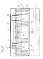
- Fig. 2 den Gegenstand nach Fig. 1 in Seitenansicht mit lediglich einem Verschlußspanner,
- Fig. 3 einen erfindungsgemäßen Verschlußspanner in explosiver Seitenansicht,
- Fig. 4 einen Schnitt A-B durch den Gegenstand nach Fig. 1 in zusammengesetztem Zustand,
- Fig. 5 die Abdeckschale für den Gegenstand nach Fig. 3 in Seitenansicht,
- Fig. 6 einen Schnitt C-D durch die Abdeckschale gemäß Fig. 3 und
- Fig. 7 den Spannbügel gemäß Fig. 3 in Seitenansicht.
- In den Figuren ist eine Vorrichtung zum Verschließen einer Kabelmuffe für das Verbinden und Abzweigen von Kabeln, insbes. Fernmeldekabeln, dargestellt. Die Kabelmuffe weist ein längsgeteiltes Muffenrohr 1 aus biegeelastischem bzw. thermoplastischem Kunststoff auf. Die Längsteilung wird von Verschlußprofilen 2a, 2b mit jeweils einer Hinterschneidung 3 begrenzt. Die aus der Längsteilung resultierenden Längsränder 4 des Muffenrohres 1 sind mittels eines in die Hinterschneidungen 3 eingreifenden und die Verschlußprofile 2 übergreifenden Verschlusses in Schließstellung zusammengehalten. Der Verschluß ist als Verschlußspanner mit einer Abdeckschale 5 und einem Spannbügel 6 ausgebildet. Die Abdeckschale 5 weist an ihrer einen Längsseite eine Klaue 7 zum Hintergreifen des einen Verschlußprofils 2a auf, während an ihrer anderen Längsseite der Spannbügel 6 schwenkbar gelagert ist. Der Spannbügel 6 bildet in ein geschwenktem Zustand eine Klaue 8 zum Hintergreifen des anderen Verschlußprofils 2b. Bei über einen Totpunkt hinaus eingeschwenktem Spannbügel 6 sind die Längsränder 4 des Muffenrohres 1 zusammengedrückt, ist die Längsteilung des Muffenrohres 1 unter Zwischenschaltung eines Dichtmittels 9 einwandfrei abgedichtet. In gespanntem Zustand kann der Verschlußspanner 5, 6 zusätzlich gegen unbeabsichtigtes Lösen gesichert werden, beispielsweise mittels einer Sicherung 10, die einerseits an den Verschlußspanner 5, 6, andererseits an Haltenocken 11 auf dem Außenumfang des Muffenrohres 1 verankerbar ist.
- Die Abdeckschale 5 ist als Stahlblechschale ausgeführt und weist Verstärkungssicken 12 auf. Die Klaue 7 der Abdeckschale 5 ist von einer Umbiegung ihres freien Längsrandes gebildet. Die Abdeckschale 5 weist an ihrer der Klaue 7 abgewandten Längsseite einen Scharnierbolzen 13 und Schwenkausnehmungen 14 für den unter Bildung eines Scharniers schwenkbar angeschlossenen Spannbügel 6 auf. Ferner besitzt die Abdeckschale 5 eine Abwinkelung 15 mit dem Scharnierbolzen 13 und den Schwenkausnehmungen 14 zur Anpassung an den Außenumfang des Muffenrohres 1 im Bereich seiner Längsteilung. Der Spannbügel 6 weist im Bereich der Schwenkausnehmungen 14 sich orthogonal zur Scharnierachse erstreckende Einstecktaschen 16 zum Einstecken eines angedeuteten Betätigungswerkzeuges 17 auf. Die Einstecktaschen 16 besitzen Lager 18 für den Scharnierbolzen 13. Der Spannbügel 6 besteht ebenfalls aus Stahlbleck, jedoch mit sich orthogonal zur Scharnierachse erstreckenden Scharnierlaschen 19, welche eingeformte Lagerausnehmungen 20 für den Scharnierbolzen 13 und senkrecht zu den Lageraus nehmungen 20 eingeformte Steckausnehmungen 21 für das Betätigungswerkzeug 17 aufweisen. Auf den Scharnierlaschen 19 sind unter Bildung der Einstecktaschen 16 die Lagerausnehmungen 20 begrenzende bzw. lagerbildende und die Steckausnehmungen 21 ergänzende Deckbleche 22 befestigt.
Claims (7)
Priority Applications (1)
| Application Number | Priority Date | Filing Date | Title |
|---|---|---|---|
| AT90118446T ATE103118T1 (de) | 1989-09-30 | 1990-09-26 | Vorrichtung zum verschliessen einer kabelmuffe fuer das verbinden und abzweigen von kabeln, insbesondere fernmeldekabeln. |
Applications Claiming Priority (4)
| Application Number | Priority Date | Filing Date | Title |
|---|---|---|---|
| DE3932734 | 1989-09-30 | ||
| DE3932734 | 1989-09-30 | ||
| DE8914665U DE8914665U1 (de) | 1989-09-30 | 1989-12-14 | Vorrichtung zum Verschließen einer Kabelmuffe für das Verbinden und Abzweigen von Kabeln, insbesondere Fernmeldekabeln |
| DE8914665U | 1989-12-14 |
Publications (3)
| Publication Number | Publication Date |
|---|---|
| EP0421253A2 true EP0421253A2 (de) | 1991-04-10 |
| EP0421253A3 EP0421253A3 (en) | 1991-09-18 |
| EP0421253B1 EP0421253B1 (de) | 1994-03-16 |
Family
ID=25885709
Family Applications (1)
| Application Number | Title | Priority Date | Filing Date |
|---|---|---|---|
| EP90118446A Expired - Lifetime EP0421253B1 (de) | 1989-09-30 | 1990-09-26 | Vorrichtung zum Verschliessen einer Kabelmuffe für das Verbinden und Abzweigen von Kabeln, insbesondere Fernmeldekabeln |
Country Status (7)
| Country | Link |
|---|---|
| US (1) | US5111556A (de) |
| EP (1) | EP0421253B1 (de) |
| AT (1) | ATE103118T1 (de) |
| DE (2) | DE8914665U1 (de) |
| DK (1) | DK0421253T3 (de) |
| ES (1) | ES2051428T3 (de) |
| TR (1) | TR24643A (de) |
Cited By (3)
| Publication number | Priority date | Publication date | Assignee | Title |
|---|---|---|---|---|
| DE9107915U1 (de) * | 1991-06-27 | 1991-09-05 | Stewing Kunststoffbetrieb GmbH, 4270 Dorsten | Kabelmuffe |
| WO1995020773A3 (en) * | 1994-01-26 | 1995-12-07 | Raychem Corp | Aerial, pedestal, below grade, or buried optical fiber closure |
| CN107592950A (zh) * | 2015-05-06 | 2018-01-16 | 伊顿保护系统Ip有限两合公司 | 电缆/线缆插入装置 |
Families Citing this family (9)
| Publication number | Priority date | Publication date | Assignee | Title |
|---|---|---|---|---|
| DE8914665U1 (de) * | 1989-09-30 | 1990-02-15 | Stewing Kunststoffbetrieb GmbH, 4270 Dorsten | Vorrichtung zum Verschließen einer Kabelmuffe für das Verbinden und Abzweigen von Kabeln, insbesondere Fernmeldekabeln |
| DE4140977C1 (de) * | 1991-12-12 | 1993-05-06 | Stewing Kunststoffbetrieb Gmbh, 4270 Dorsten, De | |
| GB9419033D0 (en) * | 1994-09-21 | 1994-11-09 | Raychem Sa Nv | Retention slip |
| DE202006012464U1 (de) * | 2006-08-12 | 2007-12-27 | Rehau Ag + Co. | Abdeckungsvorrichtung |
| EP2520959B1 (de) | 2011-05-05 | 2014-03-12 | CCS Technology, Inc. | Kabelzugentlastungsvorrichtung für Kabelenden und Kabelenden mit mindestens einer solchen Kabelzugentlastungsvorrichtung |
| EP2520960B1 (de) * | 2011-05-05 | 2014-07-09 | CCS Technology, Inc. | Kabelmuffe |
| CN102931624A (zh) * | 2012-11-14 | 2013-02-13 | 山东电力集团公司济南供电公司 | 一种自锁定快速插拔接头保护盒 |
| CN106043951B (zh) * | 2016-07-29 | 2018-10-30 | 莱芜钢铁集团有限公司 | 吊挂电缆夹 |
| DE202017102147U1 (de) * | 2017-04-10 | 2017-05-05 | Igus Gmbh | Leitungsdurchführung, insbesondere Zugentlastung für eine Energieführungskette |
Family Cites Families (14)
| Publication number | Priority date | Publication date | Assignee | Title |
|---|---|---|---|---|
| FR663925A (fr) * | 1928-11-14 | 1929-08-27 | Perfectionnements apportés aux boucles de fermeture de malles d'automobiles et autres | |
| US2751240A (en) * | 1953-11-30 | 1956-06-19 | Bassick Co | Lid fastener |
| US2862275A (en) * | 1956-10-15 | 1958-12-02 | Ladish Co | Toggle-type connecting assemblies having detachable connecting bails |
| US3007722A (en) * | 1956-11-13 | 1961-11-07 | Snappy Inc | Heating conduit splice |
| US3183569A (en) * | 1962-04-19 | 1965-05-18 | Engman Mfg Company | Clamp means |
| US3455336A (en) * | 1965-11-03 | 1969-07-15 | Raychem Corp | Heat recoverable article and process |
| DE2249368C3 (de) * | 1972-10-09 | 1975-03-27 | Krone Gmbh, 1000 Berlin | Verbindungs- und Abzweigmuffe für Fernmeldekabel |
| DE7344926U (de) * | 1973-12-19 | 1976-06-03 | Felten & Guilleaume Schaltanlagen Gmbh, 4150 Krefeld | Längsgeteilte Muffe für elektrische Kabel mit Verbindungselementen |
| DE7608590U1 (de) * | 1976-03-19 | 1976-08-26 | Siemens Ag, 1000 Berlin Und 8000 Muenchen | Längsgeschlitzte oder -geteilte zylinderförmige Kabelgarnitur, insbesondere zylindrisches Muffenrohr mit SpannblechverschluB |
| DE3047457C2 (de) * | 1980-12-17 | 1982-09-09 | Karl Dipl.-Ing.(FH) 4040 Neuss Weinhold | Rohrverbindung zum Verbinden zweier Rohrenden |
| JPS5815679A (ja) * | 1981-07-16 | 1983-01-29 | 隆祥産業株式会社 | 荷締具 |
| US4538021A (en) * | 1984-04-06 | 1985-08-27 | At&T Bell Laboratories, Inc. | Cable closure having asymmetrical end plate assembly |
| US4810829A (en) * | 1987-12-11 | 1989-03-07 | Minnesota Mining And Manufacturing Co. | Cable closure |
| DE8914665U1 (de) * | 1989-09-30 | 1990-02-15 | Stewing Kunststoffbetrieb GmbH, 4270 Dorsten | Vorrichtung zum Verschließen einer Kabelmuffe für das Verbinden und Abzweigen von Kabeln, insbesondere Fernmeldekabeln |
-
1989
- 1989-12-14 DE DE8914665U patent/DE8914665U1/de not_active Expired - Lifetime
-
1990
- 1990-09-26 ES ES90118446T patent/ES2051428T3/es not_active Expired - Lifetime
- 1990-09-26 AT AT90118446T patent/ATE103118T1/de not_active IP Right Cessation
- 1990-09-26 DE DE90118446T patent/DE59005003D1/de not_active Expired - Fee Related
- 1990-09-26 EP EP90118446A patent/EP0421253B1/de not_active Expired - Lifetime
- 1990-09-26 DK DK90118446.5T patent/DK0421253T3/da active
- 1990-09-28 US US07/590,474 patent/US5111556A/en not_active Expired - Fee Related
- 1990-10-08 TR TR90/0926A patent/TR24643A/xx unknown
Cited By (4)
| Publication number | Priority date | Publication date | Assignee | Title |
|---|---|---|---|---|
| DE9107915U1 (de) * | 1991-06-27 | 1991-09-05 | Stewing Kunststoffbetrieb GmbH, 4270 Dorsten | Kabelmuffe |
| WO1995020773A3 (en) * | 1994-01-26 | 1995-12-07 | Raychem Corp | Aerial, pedestal, below grade, or buried optical fiber closure |
| US5556060A (en) * | 1994-01-26 | 1996-09-17 | Raychem Corporation | Aerial pedestal below grade or buried optical fiber |
| CN107592950A (zh) * | 2015-05-06 | 2018-01-16 | 伊顿保护系统Ip有限两合公司 | 电缆/线缆插入装置 |
Also Published As
| Publication number | Publication date |
|---|---|
| TR24643A (tr) | 1992-01-01 |
| EP0421253A3 (en) | 1991-09-18 |
| US5111556A (en) | 1992-05-12 |
| DE8914665U1 (de) | 1990-02-15 |
| ATE103118T1 (de) | 1994-04-15 |
| DK0421253T3 (da) | 1994-05-02 |
| EP0421253B1 (de) | 1994-03-16 |
| ES2051428T3 (es) | 1994-06-16 |
| DE59005003D1 (de) | 1994-04-21 |
Similar Documents
| Publication | Publication Date | Title |
|---|---|---|
| DE69816935T2 (de) | Manschette für ein Rohrelement | |
| DE3300779A1 (de) | Kabelschelle fuer variable durchmesser | |
| DE3126488A1 (de) | Rohrschelle | |
| EP0421253A2 (de) | Vorrichtung zum Verschliessen einer Kabelmuffe für das Verbinden und Abzweigen von Kabeln, insbesondere Fernmeldekabeln | |
| DE69416407T2 (de) | Verfahren und befestigungsvorrichtung zum ermitteln der position eines rohres, schlauches oder eines ähnlichen elementes | |
| EP1319133B1 (de) | Blechklammer | |
| DE2932979A1 (de) | Klemmeinrichtung | |
| EP1798459A1 (de) | Rohrverbindungsvorrichtung aus zwei halbschalenartigen Halteelementen | |
| DE19734355C1 (de) | Preßwerkzeug | |
| EP0440903A1 (de) | Anpassungsdichtelement für den Abschluss einer Einführungsöffnung bei Kabelgarnituren, Rohrzügen oder dergleichen | |
| EP0040258A1 (de) | Kunststoffschlauchschelle | |
| WO2019211053A1 (de) | Schelle | |
| DE102010053357A1 (de) | Rohrschelle | |
| EP2833497B1 (de) | Befestigungselement | |
| DD295962A5 (de) | Vorrichtung zum verschliessen einer kabelmuffe fuer das verbinden und abzweigen von kabeln, insbesondere fernmeldekabeln | |
| EP3205919A1 (de) | Spannschelle | |
| DE10308125A1 (de) | Klemmschelle | |
| DE69006734T2 (de) | Schutzmuffe für elektrische Kabel und dazugehöriges Verfahren. | |
| DE3303178A1 (de) | Steckerbuchse fuer elektrische leitungsadern | |
| DE3011121C2 (de) | Kabelband | |
| EP0865134B1 (de) | Aus zwei Halbschalen bestehendes Reparaturstück | |
| DE8804038U1 (de) | Verbindungsstück für Schläuche | |
| DE410081C (de) | Auswechselbarer Rohrflansch | |
| DE3216682C2 (de) | Dichtungseinrichtung für Rohrverbindungen | |
| DE3719623C2 (de) |
Legal Events
| Date | Code | Title | Description |
|---|---|---|---|
| PUAI | Public reference made under article 153(3) epc to a published international application that has entered the european phase |
Free format text: ORIGINAL CODE: 0009012 |
|
| AK | Designated contracting states |
Kind code of ref document: A2 Designated state(s): AT BE CH DE DK ES FR GB GR IT LI LU NL SE |
|
| PUAL | Search report despatched |
Free format text: ORIGINAL CODE: 0009013 |
|
| 17P | Request for examination filed |
Effective date: 19910706 |
|
| AK | Designated contracting states |
Kind code of ref document: A3 Designated state(s): AT BE CH DE DK ES FR GB GR IT LI LU NL SE |
|
| 17Q | First examination report despatched |
Effective date: 19930519 |
|
| GRAA | (expected) grant |
Free format text: ORIGINAL CODE: 0009210 |
|
| AK | Designated contracting states |
Kind code of ref document: B1 Designated state(s): AT BE CH DE DK ES FR GB GR IT LI LU NL SE |
|
| REF | Corresponds to: |
Ref document number: 103118 Country of ref document: AT Date of ref document: 19940415 Kind code of ref document: T |
|
| ITF | It: translation for a ep patent filed | ||
| REF | Corresponds to: |
Ref document number: 59005003 Country of ref document: DE Date of ref document: 19940421 |
|
| REG | Reference to a national code |
Ref country code: DK Ref legal event code: T3 |
|
| ET | Fr: translation filed | ||
| GBT | Gb: translation of ep patent filed (gb section 77(6)(a)/1977) |
Effective date: 19940426 |
|
| REG | Reference to a national code |
Ref country code: ES Ref legal event code: FG2A Ref document number: 2051428 Country of ref document: ES Kind code of ref document: T3 |
|
| REG | Reference to a national code |
Ref country code: GR Ref legal event code: FG4A Free format text: 3011551 |
|
| PLBE | No opposition filed within time limit |
Free format text: ORIGINAL CODE: 0009261 |
|
| STAA | Information on the status of an ep patent application or granted ep patent |
Free format text: STATUS: NO OPPOSITION FILED WITHIN TIME LIMIT |
|
| EAL | Se: european patent in force in sweden |
Ref document number: 90118446.5 |
|
| 26N | No opposition filed | ||
| PGFP | Annual fee paid to national office [announced via postgrant information from national office to epo] |
Ref country code: DK Payment date: 19950918 Year of fee payment: 6 |
|
| PGFP | Annual fee paid to national office [announced via postgrant information from national office to epo] |
Ref country code: SE Payment date: 19950920 Year of fee payment: 6 |
|
| PGFP | Annual fee paid to national office [announced via postgrant information from national office to epo] |
Ref country code: FR Payment date: 19950929 Year of fee payment: 6 |
|
| PG25 | Lapsed in a contracting state [announced via postgrant information from national office to epo] |
Ref country code: DK Effective date: 19960926 |
|
| REG | Reference to a national code |
Ref country code: DK Ref legal event code: EBP |
|
| PG25 | Lapsed in a contracting state [announced via postgrant information from national office to epo] |
Ref country code: SE Effective date: 19960927 |
|
| PG25 | Lapsed in a contracting state [announced via postgrant information from national office to epo] |
Ref country code: FR Effective date: 19960930 |
|
| PGFP | Annual fee paid to national office [announced via postgrant information from national office to epo] |
Ref country code: CH Payment date: 19960930 Year of fee payment: 7 |
|
| EUG | Se: european patent has lapsed |
Ref document number: 90118446.5 |
|
| REG | Reference to a national code |
Ref country code: FR Ref legal event code: ST |
|
| REG | Reference to a national code |
Ref country code: FR Ref legal event code: ST |
|
| PG25 | Lapsed in a contracting state [announced via postgrant information from national office to epo] |
Ref country code: LI Free format text: LAPSE BECAUSE OF NON-PAYMENT OF DUE FEES Effective date: 19970930 Ref country code: CH Free format text: LAPSE BECAUSE OF NON-PAYMENT OF DUE FEES Effective date: 19970930 |
|
| REG | Reference to a national code |
Ref country code: CH Ref legal event code: PL |
|
| REG | Reference to a national code |
Ref country code: GB Ref legal event code: 732E |
|
| NLS | Nl: assignments of ep-patents |
Owner name: KRONE AKTIENGESELLSCHAFT |
|
| PGFP | Annual fee paid to national office [announced via postgrant information from national office to epo] |
Ref country code: GR Payment date: 20000830 Year of fee payment: 11 |
|
| PGFP | Annual fee paid to national office [announced via postgrant information from national office to epo] |
Ref country code: LU Payment date: 20000831 Year of fee payment: 11 |
|
| PGFP | Annual fee paid to national office [announced via postgrant information from national office to epo] |
Ref country code: NL Payment date: 20000929 Year of fee payment: 12 |
|
| PGFP | Annual fee paid to national office [announced via postgrant information from national office to epo] |
Ref country code: AT Payment date: 20000930 Year of fee payment: 11 |
|
| NLS | Nl: assignments of ep-patents |
Owner name: KRONE GMBH |
|
| PG25 | Lapsed in a contracting state [announced via postgrant information from national office to epo] |
Ref country code: LU Free format text: LAPSE BECAUSE OF NON-PAYMENT OF DUE FEES Effective date: 20010926 Ref country code: AT Free format text: LAPSE BECAUSE OF NON-PAYMENT OF DUE FEES Effective date: 20010926 |
|
| PG25 | Lapsed in a contracting state [announced via postgrant information from national office to epo] |
Ref country code: NL Free format text: LAPSE BECAUSE OF NON-PAYMENT OF DUE FEES Effective date: 20010930 Ref country code: GR Free format text: LAPSE BECAUSE OF NON-PAYMENT OF DUE FEES Effective date: 20010930 |
|
| REG | Reference to a national code |
Ref country code: ES Ref legal event code: PC2A |
|
| REG | Reference to a national code |
Ref country code: GB Ref legal event code: IF02 |
|
| NLV4 | Nl: lapsed or anulled due to non-payment of the annual fee |
Effective date: 20020401 |
|
| PGFP | Annual fee paid to national office [announced via postgrant information from national office to epo] |
Ref country code: GB Payment date: 20020918 Year of fee payment: 13 |
|
| PGFP | Annual fee paid to national office [announced via postgrant information from national office to epo] |
Ref country code: DE Payment date: 20020930 Year of fee payment: 13 |
|
| PGFP | Annual fee paid to national office [announced via postgrant information from national office to epo] |
Ref country code: ES Payment date: 20021009 Year of fee payment: 13 |
|
| PGFP | Annual fee paid to national office [announced via postgrant information from national office to epo] |
Ref country code: BE Payment date: 20030306 Year of fee payment: 13 |
|
| NLV4 | Nl: lapsed or anulled due to non-payment of the annual fee |
Effective date: 20020401 |
|
| PG25 | Lapsed in a contracting state [announced via postgrant information from national office to epo] |
Ref country code: GB Free format text: LAPSE BECAUSE OF NON-PAYMENT OF DUE FEES Effective date: 20030926 |
|
| PG25 | Lapsed in a contracting state [announced via postgrant information from national office to epo] |
Ref country code: ES Free format text: LAPSE BECAUSE OF NON-PAYMENT OF DUE FEES Effective date: 20030927 |
|
| PG25 | Lapsed in a contracting state [announced via postgrant information from national office to epo] |
Ref country code: BE Free format text: LAPSE BECAUSE OF NON-PAYMENT OF DUE FEES Effective date: 20030930 |
|
| BERE | Be: lapsed |
Owner name: *KRONE A.G. Effective date: 20030930 |
|
| PG25 | Lapsed in a contracting state [announced via postgrant information from national office to epo] |
Ref country code: DE Free format text: LAPSE BECAUSE OF NON-PAYMENT OF DUE FEES Effective date: 20040401 |
|
| GBPC | Gb: european patent ceased through non-payment of renewal fee |
Effective date: 20030926 |
|
| REG | Reference to a national code |
Ref country code: ES Ref legal event code: FD2A Effective date: 20030927 |
|
| PG25 | Lapsed in a contracting state [announced via postgrant information from national office to epo] |
Ref country code: IT Free format text: LAPSE BECAUSE OF NON-PAYMENT OF DUE FEES;WARNING: LAPSES OF ITALIAN PATENTS WITH EFFECTIVE DATE BEFORE 2007 MAY HAVE OCCURRED AT ANY TIME BEFORE 2007. THE CORRECT EFFECTIVE DATE MAY BE DIFFERENT FROM THE ONE RECORDED. Effective date: 20050926 |