EP0421048B1 - Bordure de sécurité - Google Patents
Bordure de sécurité Download PDFInfo
- Publication number
- EP0421048B1 EP0421048B1 EP90107614A EP90107614A EP0421048B1 EP 0421048 B1 EP0421048 B1 EP 0421048B1 EP 90107614 A EP90107614 A EP 90107614A EP 90107614 A EP90107614 A EP 90107614A EP 0421048 B1 EP0421048 B1 EP 0421048B1
- Authority
- EP
- European Patent Office
- Prior art keywords
- contact
- wedge
- plates
- elements
- plate
- Prior art date
- Legal status (The legal status is an assumption and is not a legal conclusion. Google has not performed a legal analysis and makes no representation as to the accuracy of the status listed.)
- Expired - Lifetime
Links
Images
Classifications
-
- H—ELECTRICITY
- H01—ELECTRIC ELEMENTS
- H01H—ELECTRIC SWITCHES; RELAYS; SELECTORS; EMERGENCY PROTECTIVE DEVICES
- H01H3/00—Mechanisms for operating contacts
- H01H3/02—Operating parts, i.e. for operating driving mechanism by a mechanical force external to the switch
- H01H3/14—Operating parts, i.e. for operating driving mechanism by a mechanical force external to the switch adapted for operation by a part of the human body other than the hand, e.g. by foot
- H01H3/141—Cushion or mat switches
-
- E—FIXED CONSTRUCTIONS
- E05—LOCKS; KEYS; WINDOW OR DOOR FITTINGS; SAFES
- E05F—DEVICES FOR MOVING WINGS INTO OPEN OR CLOSED POSITION; CHECKS FOR WINGS; WING FITTINGS NOT OTHERWISE PROVIDED FOR, CONCERNED WITH THE FUNCTIONING OF THE WING
- E05F15/00—Power-operated mechanisms for wings
- E05F15/40—Safety devices, e.g. detection of obstructions or end positions
- E05F15/42—Detection using safety edges
- E05F15/44—Detection using safety edges responsive to changes in electrical conductivity
-
- F—MECHANICAL ENGINEERING; LIGHTING; HEATING; WEAPONS; BLASTING
- F16—ENGINEERING ELEMENTS AND UNITS; GENERAL MEASURES FOR PRODUCING AND MAINTAINING EFFECTIVE FUNCTIONING OF MACHINES OR INSTALLATIONS; THERMAL INSULATION IN GENERAL
- F16P—SAFETY DEVICES IN GENERAL; SAFETY DEVICES FOR PRESSES
- F16P3/00—Safety devices acting in conjunction with the control or operation of a machine; Control arrangements requiring the simultaneous use of two or more parts of the body
- F16P3/12—Safety devices acting in conjunction with the control or operation of a machine; Control arrangements requiring the simultaneous use of two or more parts of the body with means, e.g. feelers, which in case of the presence of a body part of a person in or near the danger zone influence the control or operation of the machine
-
- E—FIXED CONSTRUCTIONS
- E05—LOCKS; KEYS; WINDOW OR DOOR FITTINGS; SAFES
- E05F—DEVICES FOR MOVING WINGS INTO OPEN OR CLOSED POSITION; CHECKS FOR WINGS; WING FITTINGS NOT OTHERWISE PROVIDED FOR, CONCERNED WITH THE FUNCTIONING OF THE WING
- E05F15/00—Power-operated mechanisms for wings
- E05F15/40—Safety devices, e.g. detection of obstructions or end positions
- E05F15/42—Detection using safety edges
- E05F15/44—Detection using safety edges responsive to changes in electrical conductivity
- E05F2015/447—Detection using safety edges responsive to changes in electrical conductivity using switches in serial arrangement
-
- H—ELECTRICITY
- H01—ELECTRIC ELEMENTS
- H01H—ELECTRIC SWITCHES; RELAYS; SELECTORS; EMERGENCY PROTECTIVE DEVICES
- H01H3/00—Mechanisms for operating contacts
- H01H3/02—Operating parts, i.e. for operating driving mechanism by a mechanical force external to the switch
- H01H3/14—Operating parts, i.e. for operating driving mechanism by a mechanical force external to the switch adapted for operation by a part of the human body other than the hand, e.g. by foot
- H01H3/141—Cushion or mat switches
- H01H2003/146—Cushion or mat switches being normally closed
Definitions
- the invention relates to a safety bar according to the preamble of the main claim.
- a generic security bar is described in DE-C-36 06 499.
- contact rollers are used, which are forced towards one another via an expander cord.
- Insulated wedge rollers are arranged between the contact rollers and are arranged with wedge surfaces between the individual contact rollers which are oriented radially to the insulating wedge roller axis and project into the interior of the insulating wedge rollers.
- the invention has for its object to provide a safety bar that has only a low profile, i.e. builds very flat and covers a large area securely.
- contact plates be used, between which wedge plates are arranged.
- the two components are forced towards one another by means of one or more expander cords and both components have wedge surfaces on their mutually facing end surfaces, so that the two components, under the tension of the expander cord, endeavor to deflect upwards or downwards.
- the evasive movement is limited by the expander cord arranged in the two components.
- the cooperating edges of these components are dovetail-shaped, so that, for. B. the contact plates are caught in the wedge plates.
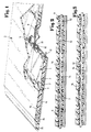
- a safety bar 1 is drawn, which forms a safety mat 2.
- the actual safety bar consists of contact plates 6 and wedge plates 7, which abut one another via inclined end surfaces 3 and 4. Bores 9 and 10 are provided in the contact plates 6 and the wedge plates 7, which receive an expander cord 12, two expander cords 12 being provided in the exemplary embodiment shown.
- the wedge plates 7 are made smaller than the contact plates 6 and thus it is possible for the contact plates 6 to have a contact region in their central region which has a contact point 5. In the normal state shown in Fig. 1, the contact points 5 of the contact plates 6 abut each other and thereby a current circuit (closed circuit) is given.
- the actual safety bar is located within a housing, which consists of a base plate 14, a drive-on edge 15 and a cover plate 16, the drive-on edge 15 and the cover plate 16 being relatively elastic, while the base plate 14 is made of one can be provided with an insulating coating sheet metal component.
- Fig. 3 shows an embodiment in which the cooperating edge edges of the wedge plates 7 and contact plates 6 are dovetail-shaped, so that a limitation of the movement of the two plates 6 and 7 against each other is achieved.
Claims (4)
- Bordure de sécurité (1) présentant un dispositif de commutation électrique, laquelle se compose d'une pluralité d'éléments de contact et d'éléments en forme de coin disposés en rangées, dont les éléments de contact sont contigus les uns des autres dans la position de repos sous l'action d'une précontrainte élastique en des points de contact (5) prévus sur leurs faces antérieures et sont écartés les uns des autres sous l'action d'une force extérieure exercée sur la bordure de sécurité (1) en interrompant le contact, au moins un cordon extensible (12) forçant les différents éléments de contact les uns vers les autres par leurs points de contact (5) dans le sens axial et les surfaces d'extrémité orientées les unes vers les autres des éléments de contact et des éléments coniques étant inclinées par rapport à l'axe longitudinal axial des éléments de contact, caractérisée en ce quea) les éléments de contact sont conçus comme des plaques de contact (6),b) les éléments en forme de coin sont conçus comme des plaques en forme de coin (7),c) à l'état prêt à commuter le cordon extensible (12) se trouve à une hauteur différente dans les plaques de contact (6) et les plaques en forme de coin (7).
- Bordure de sécurité selon la revendication 1, caractérisée en ce que le trou (9) dans la plaque de contact (6) et le trou (10) dans la plaque en forme de coin (7) recevant le cordon extensible correspondent chacun sensiblement au diamètre du cordon extensible, mais sont disposés à une hauteur différente.
- Bordure de sécurité selon la revendication 1, caractérisée en ce que le trou (9) dans la plaque de contact (6) et le trou (10) dans la plaque en forme de coin recevant le cordon extensible présentent un plus grand diamètre que le cordon extensible, mais se trouvent à la même hauteur à l'intérieur des plaques.
- Bordure de sécurité selon l'une quelconque des revendications précédentes, caractérisée en ce que les bords des plaques en forme de coin (7) et des plaques de contact (6) se trouvant en contact les uns avec les autres sont conformés en queue d'aronde.
Applications Claiming Priority (2)
| Application Number | Priority Date | Filing Date | Title |
|---|---|---|---|
| DE3932820 | 1989-09-30 | ||
| DE3932820A DE3932820C1 (fr) | 1989-09-30 | 1989-09-30 |
Publications (2)
| Publication Number | Publication Date |
|---|---|
| EP0421048A1 EP0421048A1 (fr) | 1991-04-10 |
| EP0421048B1 true EP0421048B1 (fr) | 1993-05-19 |
Family
ID=6390650
Family Applications (1)
| Application Number | Title | Priority Date | Filing Date |
|---|---|---|---|
| EP90107614A Expired - Lifetime EP0421048B1 (fr) | 1989-09-30 | 1990-04-21 | Bordure de sécurité |
Country Status (2)
| Country | Link |
|---|---|
| EP (1) | EP0421048B1 (fr) |
| DE (2) | DE3932820C1 (fr) |
Cited By (3)
| Publication number | Priority date | Publication date | Assignee | Title |
|---|---|---|---|---|
| BE1005078A3 (fr) * | 1991-07-17 | 1993-04-13 | Bianco Camillo Del | Dispositif de protection, en particulier dispositif de protection contre l'effraction de portes. |
| EP1239108A2 (fr) | 2001-03-06 | 2002-09-11 | André Haake | Bordure à interrupteur pour sécurité d'un bord de fermeture |
| DE102004025786B3 (de) * | 2004-04-29 | 2005-04-28 | Andre Haake | Sicherheitsleiste als Schaltleiste |
Families Citing this family (7)
| Publication number | Priority date | Publication date | Assignee | Title |
|---|---|---|---|---|
| DE4319386C1 (de) * | 1993-06-11 | 1994-07-21 | Andre Haake | Elektrische Schalteinrichtung |
| DE19647720B4 (de) * | 1996-11-19 | 2004-05-13 | Wampfler Aktiengesellschaft | Schließkantensicherheitsleiste |
| DE19918747C1 (de) * | 1999-04-24 | 2001-03-15 | Andre Haake | Druckempfindliche Schalteinrichtung |
| DE20103732U1 (de) * | 2001-03-03 | 2001-06-21 | Haake Andre | Druckempfindliche Schalteinrichtung in Form einer flachbauenden Schaltmatte |
| DE10129183A1 (de) * | 2001-06-19 | 2003-01-02 | Aso Gmbh Antriebs Und Steuerun | Sicherheitskontaktmatte |
| DE102005018146B3 (de) | 2005-04-02 | 2006-05-18 | Haake, André | Sicherheitsleiste für eine Schließkantensicherung |
| DE102005040947B4 (de) * | 2005-08-30 | 2007-07-26 | Iht-Innovative Hebe Technik Gmbh | Signalgebende Schaltleiste für Sicherheitseinrichtungen |
Family Cites Families (3)
| Publication number | Priority date | Publication date | Assignee | Title |
|---|---|---|---|---|
| CH657474A5 (de) * | 1982-09-13 | 1986-08-29 | Inventio Ag | Sicherheitsleiste. |
| DE3606499C1 (de) * | 1986-02-28 | 1987-07-16 | Werner Haake | Schliesskanten-Sicherung |
| DE3821305A1 (de) * | 1988-06-24 | 1990-02-22 | Andre Haake | Schliesskanten-sicherung |
-
1989
- 1989-09-30 DE DE3932820A patent/DE3932820C1/de not_active Expired - Lifetime
-
1990
- 1990-04-21 EP EP90107614A patent/EP0421048B1/fr not_active Expired - Lifetime
- 1990-04-21 DE DE9090107614T patent/DE59001486D1/de not_active Expired - Fee Related
Cited By (3)
| Publication number | Priority date | Publication date | Assignee | Title |
|---|---|---|---|---|
| BE1005078A3 (fr) * | 1991-07-17 | 1993-04-13 | Bianco Camillo Del | Dispositif de protection, en particulier dispositif de protection contre l'effraction de portes. |
| EP1239108A2 (fr) | 2001-03-06 | 2002-09-11 | André Haake | Bordure à interrupteur pour sécurité d'un bord de fermeture |
| DE102004025786B3 (de) * | 2004-04-29 | 2005-04-28 | Andre Haake | Sicherheitsleiste als Schaltleiste |
Also Published As
| Publication number | Publication date |
|---|---|
| DE59001486D1 (de) | 1993-06-24 |
| EP0421048A1 (fr) | 1991-04-10 |
| DE3932820C1 (fr) | 1990-10-25 |
Similar Documents
| Publication | Publication Date | Title |
|---|---|---|
| EP0421048B1 (fr) | Bordure de sécurité | |
| DE3208559A1 (de) | Tastatur | |
| EP0019141B1 (fr) | Interrupteur à cames | |
| DE3821305C2 (fr) | ||
| EP0767474B1 (fr) | Bouton poussair | |
| DE4422698C2 (de) | Schaltanordnung mit zwei in unterschiedlichen Ebenen parallel übereinander angeordneten Kontaktflächen | |
| DE2940807A1 (de) | Elektrischer mehrfach- bzw. doppelschalter | |
| DE2926683C2 (de) | Gabelumschalter für Fernsprechapparate | |
| WO2004055845A1 (fr) | Dispositif pour actionner des groupes de fonction electriques, notamment un klaxon monte sur le volant d'un vehicule a moteur | |
| DE1214305B (de) | Mechanische Vorrichtung zur gegenseitigen Verriegelung zweier elektrischer Schaltgeraete | |
| EP0544124B1 (fr) | Clavier à boutons-poussoirs en matière synthétique, en particulier pour appareils terminaux de communication | |
| DE2851738C2 (de) | Kontaktanordnung | |
| DE2653001C3 (de) | Elektrischer Trennschalter mit rascher Trennung und Sicherheits-Zwangsunterbrechung | |
| DE2025982B2 (de) | Mehrfachkontaktsystem fuer nockenschalter | |
| DE3242134C2 (fr) | ||
| DE2452944C3 (de) | Tastenschaltersystem | |
| DE2636164A1 (de) | Allrichtungs-traegheitsschalter | |
| DE2554177A1 (de) | Schaltelement | |
| EP0303159B1 (fr) | Etrier pour un jeu de ressorts de contact électrique | |
| DE19522773C2 (de) | Tastatur | |
| WO2000065620A1 (fr) | Natte de commutation s'utilisant comme dispositif de securite | |
| WO2005083731A1 (fr) | Ensemble de contacts de commutation | |
| DE2754296B2 (de) | Druckschalter | |
| DE652744C (de) | Malschloss fuer elektrische Stromkreise | |
| DE2907894C2 (fr) |
Legal Events
| Date | Code | Title | Description |
|---|---|---|---|
| PUAI | Public reference made under article 153(3) epc to a published international application that has entered the european phase |
Free format text: ORIGINAL CODE: 0009012 |
|
| AK | Designated contracting states |
Kind code of ref document: A1 Designated state(s): DE ES FR GB NL SE |
|
| 17P | Request for examination filed |
Effective date: 19910325 |
|
| 17Q | First examination report despatched |
Effective date: 19920914 |
|
| GRAA | (expected) grant |
Free format text: ORIGINAL CODE: 0009210 |
|
| AK | Designated contracting states |
Kind code of ref document: B1 Designated state(s): DE ES FR GB NL SE |
|
| PG25 | Lapsed in a contracting state [announced via postgrant information from national office to epo] |
Ref country code: ES Free format text: THE PATENT HAS BEEN ANNULLED BY A DECISION OF A NATIONAL AUTHORITY Effective date: 19930519 |
|
| REF | Corresponds to: |
Ref document number: 59001486 Country of ref document: DE Date of ref document: 19930624 |
|
| ET | Fr: translation filed | ||
| GBT | Gb: translation of ep patent filed (gb section 77(6)(a)/1977) |
Effective date: 19930726 |
|
| PLBE | No opposition filed within time limit |
Free format text: ORIGINAL CODE: 0009261 |
|
| STAA | Information on the status of an ep patent application or granted ep patent |
Free format text: STATUS: NO OPPOSITION FILED WITHIN TIME LIMIT |
|
| 26N | No opposition filed | ||
| EAL | Se: european patent in force in sweden |
Ref document number: 90107614.1 |
|
| REG | Reference to a national code |
Ref country code: GB Ref legal event code: IF02 |
|
| PGFP | Annual fee paid to national office [announced via postgrant information from national office to epo] |
Ref country code: NL Payment date: 20070417 Year of fee payment: 18 |
|
| PGFP | Annual fee paid to national office [announced via postgrant information from national office to epo] |
Ref country code: SE Payment date: 20070424 Year of fee payment: 18 |
|
| PGFP | Annual fee paid to national office [announced via postgrant information from national office to epo] |
Ref country code: GB Payment date: 20070425 Year of fee payment: 18 |
|
| PGFP | Annual fee paid to national office [announced via postgrant information from national office to epo] |
Ref country code: DE Payment date: 20080219 Year of fee payment: 19 |
|
| PGFP | Annual fee paid to national office [announced via postgrant information from national office to epo] |
Ref country code: FR Payment date: 20080418 Year of fee payment: 19 |
|
| EUG | Se: european patent has lapsed | ||
| GBPC | Gb: european patent ceased through non-payment of renewal fee |
Effective date: 20080421 |
|
| NLV4 | Nl: lapsed or anulled due to non-payment of the annual fee |
Effective date: 20081101 |
|
| PG25 | Lapsed in a contracting state [announced via postgrant information from national office to epo] |
Ref country code: NL Free format text: LAPSE BECAUSE OF NON-PAYMENT OF DUE FEES Effective date: 20081101 |
|
| PG25 | Lapsed in a contracting state [announced via postgrant information from national office to epo] |
Ref country code: GB Free format text: LAPSE BECAUSE OF NON-PAYMENT OF DUE FEES Effective date: 20080421 |
|
| REG | Reference to a national code |
Ref country code: FR Ref legal event code: ST Effective date: 20091231 |
|
| PG25 | Lapsed in a contracting state [announced via postgrant information from national office to epo] |
Ref country code: DE Free format text: LAPSE BECAUSE OF NON-PAYMENT OF DUE FEES Effective date: 20091103 |
|
| PG25 | Lapsed in a contracting state [announced via postgrant information from national office to epo] |
Ref country code: FR Free format text: LAPSE BECAUSE OF NON-PAYMENT OF DUE FEES Effective date: 20091222 |
|
| PG25 | Lapsed in a contracting state [announced via postgrant information from national office to epo] |
Ref country code: SE Free format text: LAPSE BECAUSE OF NON-PAYMENT OF DUE FEES Effective date: 20080422 |