EP0421048B1 - Sicherheitsleiste - Google Patents
Sicherheitsleiste Download PDFInfo
- Publication number
- EP0421048B1 EP0421048B1 EP90107614A EP90107614A EP0421048B1 EP 0421048 B1 EP0421048 B1 EP 0421048B1 EP 90107614 A EP90107614 A EP 90107614A EP 90107614 A EP90107614 A EP 90107614A EP 0421048 B1 EP0421048 B1 EP 0421048B1
- Authority
- EP
- European Patent Office
- Prior art keywords
- contact
- wedge
- plates
- elements
- plate
- Prior art date
- Legal status (The legal status is an assumption and is not a legal conclusion. Google has not performed a legal analysis and makes no representation as to the accuracy of the status listed.)
- Expired - Lifetime
Links
Images
Classifications
-
- H—ELECTRICITY
- H01—ELECTRIC ELEMENTS
- H01H—ELECTRIC SWITCHES; RELAYS; SELECTORS; EMERGENCY PROTECTIVE DEVICES
- H01H3/00—Mechanisms for operating contacts
- H01H3/02—Operating parts, i.e. for operating driving mechanism by a mechanical force external to the switch
- H01H3/14—Operating parts, i.e. for operating driving mechanism by a mechanical force external to the switch adapted for operation by a part of the human body other than the hand, e.g. by foot
- H01H3/141—Cushion or mat switches
-
- E—FIXED CONSTRUCTIONS
- E05—LOCKS; KEYS; WINDOW OR DOOR FITTINGS; SAFES
- E05F—DEVICES FOR MOVING WINGS INTO OPEN OR CLOSED POSITION; CHECKS FOR WINGS; WING FITTINGS NOT OTHERWISE PROVIDED FOR, CONCERNED WITH THE FUNCTIONING OF THE WING
- E05F15/00—Power-operated mechanisms for wings
- E05F15/40—Safety devices, e.g. detection of obstructions or end positions
- E05F15/42—Detection using safety edges
- E05F15/44—Detection using safety edges responsive to changes in electrical conductivity
-
- F—MECHANICAL ENGINEERING; LIGHTING; HEATING; WEAPONS; BLASTING
- F16—ENGINEERING ELEMENTS AND UNITS; GENERAL MEASURES FOR PRODUCING AND MAINTAINING EFFECTIVE FUNCTIONING OF MACHINES OR INSTALLATIONS; THERMAL INSULATION IN GENERAL
- F16P—SAFETY DEVICES IN GENERAL; SAFETY DEVICES FOR PRESSES
- F16P3/00—Safety devices acting in conjunction with the control or operation of a machine; Control arrangements requiring the simultaneous use of two or more parts of the body
- F16P3/12—Safety devices acting in conjunction with the control or operation of a machine; Control arrangements requiring the simultaneous use of two or more parts of the body with means, e.g. feelers, which in case of the presence of a body part of a person in or near the danger zone influence the control or operation of the machine
-
- E—FIXED CONSTRUCTIONS
- E05—LOCKS; KEYS; WINDOW OR DOOR FITTINGS; SAFES
- E05F—DEVICES FOR MOVING WINGS INTO OPEN OR CLOSED POSITION; CHECKS FOR WINGS; WING FITTINGS NOT OTHERWISE PROVIDED FOR, CONCERNED WITH THE FUNCTIONING OF THE WING
- E05F15/00—Power-operated mechanisms for wings
- E05F15/40—Safety devices, e.g. detection of obstructions or end positions
- E05F15/42—Detection using safety edges
- E05F15/44—Detection using safety edges responsive to changes in electrical conductivity
- E05F2015/447—Detection using safety edges responsive to changes in electrical conductivity using switches in serial arrangement
-
- H—ELECTRICITY
- H01—ELECTRIC ELEMENTS
- H01H—ELECTRIC SWITCHES; RELAYS; SELECTORS; EMERGENCY PROTECTIVE DEVICES
- H01H3/00—Mechanisms for operating contacts
- H01H3/02—Operating parts, i.e. for operating driving mechanism by a mechanical force external to the switch
- H01H3/14—Operating parts, i.e. for operating driving mechanism by a mechanical force external to the switch adapted for operation by a part of the human body other than the hand, e.g. by foot
- H01H3/141—Cushion or mat switches
- H01H2003/146—Cushion or mat switches being normally closed
Definitions
- the invention relates to a safety bar according to the preamble of the main claim.
- a generic security bar is described in DE-C-36 06 499.
- contact rollers are used, which are forced towards one another via an expander cord.
- Insulated wedge rollers are arranged between the contact rollers and are arranged with wedge surfaces between the individual contact rollers which are oriented radially to the insulating wedge roller axis and project into the interior of the insulating wedge rollers.
- the invention has for its object to provide a safety bar that has only a low profile, i.e. builds very flat and covers a large area securely.
- contact plates be used, between which wedge plates are arranged.
- the two components are forced towards one another by means of one or more expander cords and both components have wedge surfaces on their mutually facing end surfaces, so that the two components, under the tension of the expander cord, endeavor to deflect upwards or downwards.
- the evasive movement is limited by the expander cord arranged in the two components.
- the cooperating edges of these components are dovetail-shaped, so that, for. B. the contact plates are caught in the wedge plates.
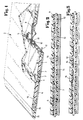
- a safety bar 1 is drawn, which forms a safety mat 2.
- the actual safety bar consists of contact plates 6 and wedge plates 7, which abut one another via inclined end surfaces 3 and 4. Bores 9 and 10 are provided in the contact plates 6 and the wedge plates 7, which receive an expander cord 12, two expander cords 12 being provided in the exemplary embodiment shown.
- the wedge plates 7 are made smaller than the contact plates 6 and thus it is possible for the contact plates 6 to have a contact region in their central region which has a contact point 5. In the normal state shown in Fig. 1, the contact points 5 of the contact plates 6 abut each other and thereby a current circuit (closed circuit) is given.
- the actual safety bar is located within a housing, which consists of a base plate 14, a drive-on edge 15 and a cover plate 16, the drive-on edge 15 and the cover plate 16 being relatively elastic, while the base plate 14 is made of one can be provided with an insulating coating sheet metal component.
- Fig. 3 shows an embodiment in which the cooperating edge edges of the wedge plates 7 and contact plates 6 are dovetail-shaped, so that a limitation of the movement of the two plates 6 and 7 against each other is achieved.
Landscapes
- Engineering & Computer Science (AREA)
- General Engineering & Computer Science (AREA)
- Mechanical Engineering (AREA)
- Push-Button Switches (AREA)
Description
- Die Erfindung bezieht sich auf eine Sicherheitsleiste gemäß dem Oberbegriff des Hauptanspruches.
- Eine gattungsbildende Sicherheitsleiste wird in der DE-C-36 06 499 beschrieben. Bei dieser bekannten Anordnung werden Kontaktrollen eingesetzt, die über eine Expanderschnur aufeinanderzu gezwungen werden. Zwischen den Kontaktrollen sind Isolierkeilwalzen angeordnet, die mit radial zur Isolierkeilwalzenachse ausgerichteten, in den Innenraum der Isolierkeilwalzen vorspringenden Keilflächen zwischen den einzelnen Kontaktrollen angeordnet sind. Durch diese Anordnung wird ein zuverlässiges Ansprechen der Schließkantensicherung erreicht, da bereits bei Belastung ein Minimum an Keilwirkung zwischen der Kontaktrolle und der Isolierkeilwalze eine Unterbrechung des Ruhestromkreises bewirkt, der selbst dann zu einer Schaltfunktion führt.
- Es wurde als nachteilig empfunden, daß die bekannte Anordnung relativ hoch bauen muß und daß sie nicht in einer plattenförmigen Gestaltung angeordnet werden kann, um beispielsweise großflächige Kontakte zu überwachen.
- Der Erfindung liegt die Aufgabe zugrunde, eine Sicherheitsleiste zu schaffen, die nur eine geringe Bauhöhe aufweist, d.h. sehr flach baut und einen großen Flächenbereich sichernd abdeckt.
- Diese der Erfindung zugrundeliegende Aufgabe wird durch die Lehre des Hauptanspruches gelöst.
- Vorteilhafte Ausgestaltungen sind in den Unteransprüchen erläutert.
- Mit anderen Worten ausgedrückt wird vorgeschlagen, daß Kontaktplatten eingesetzt werden, zwischen denen Keilplatten angeordnet sind. Die beiden Bauteile werden über eine oder mehrere Expanderschnüre aufeinanderzu gezwungen und beide Bauteile weisen an ihren aufeinanderzu gerichteten Endflächen Keilflächen auf, so daß die beiden Bauteile unter dem Zug der Expanderschnur bestrebt sind, nach oben bzw. nach unten auszuweichen. Die Ausweichbewegung wird aber durch die in den beiden Bauteilen angeordnete Expanderschnur begrenzt. Hierbei gibt es mehrere Möglichkeiten, um diese Ausweichbewegung herbeizuführen. Entscheidend ist aber, daß nunmehr bei Belastung der nach oben ausgewichenen Platte bereits ganz geringfügige Bewegungen nach unten ausreichen, die Platten auseinanderzuziehen und die Kontaktstellen zu unterbrechen und damit die Schaltfunktion herbeizuführen.
- Durch den Zusammenbau einer Vielzahl solcher Keilplatten und Kontaktplatten wird eine Schaltmatte geschaffen, die problemlos von Fahrzeugen überfahren werden kann, die aber schon bei geringer Belastung entsprechende Schaltkontakte auslöst.
- Um die Bewegung der Kontaktplatten bzw. Keilplatten nach oben oder unten zu begrenzen, sind die zusammenwirkenden Ränder dieser Bauteile schwalbenschwanzförmig ausgebildet, so daß z. B. die Kontaktplatten in den Keilplatten gefangen sind.
- Ein Ausführungsbeispiel der Erfindung wird nachfolgend anhand der Zeichnung erläutert. Die Zeichnung zeigt dabei in
- Fig. 1
- schaubildlich einen Ausschnitt aus einer Schaltmatte, in
- Fig. 2
- in größerem Maßstab den aneinander angrenzenden Bereich einer Keilplatte und einer Kontaktplatte und in
- Fig. 3
- eine gegenüber Fig. 1 und 2 abgeänderte Ausführungsform der Erfindung.
- In der Zeichnung ist eine Sicherheitsleiste 1 gezeichnet, die eine Schaltmatte 2 bildet. Die eigentliche Sicherheitsleiste besteht aus Kontaktplatten 6 und Keilplatten 7, die über schräge Endflächen 3 und 4 aneinander anliegen. In den Kontaktplatten 6 und den Keilplatten 7 sind Bohrungen 9 bzw. 10 vorgesehen, die eine Expanderschnur 12 aufnehmen, wobei bei dem dargestellten Ausführungsbeispiel zwei Expanderschnüre 12 vorgesehen sind.
- In der Darstellung in Fig. 2 ist dargestellt, daß die Bohrungen 9 und 10 einen größeren Durchmesser als die Expanderschnüre 12 aufweisen und daß im schaltbereiten Zustand die Expanderschnur 12 an der Keilplatte 7 im oberen Bereich der Bohrung 10 anliegt, während sie in der Bohrung 9 der Kontaktplatte 6 im unteren Bereich anliegt. Durch entsprechende Druckbeaufschlagung entweder auf die Keilplatte 6 oder auf die Kontaktplatte 7 bewegen sich nunmehr die beiden Endflächen 3 und 4 so gegeneinander, daß ein Auseinanderdrücken der beiden Bauteile 6 und 7 erfolgt, d.h. die Kontaktplatte 6 wird von der Keilplatte 7 entfernt.
- Die Keilplatten 7 sind kleiner ausgebildet als die Kontaktplatten 6 und somit ist es möglich, daß die Kontaktplatten 6 in ihrem mittleren Bereich einen Kontaktbereich aufweisen, der eine Kontaktstelle 5 besitzt. Im normalen in Fig. 1 dargestellten Zustand liegen die Kontaktstellen 5 der Kontaktplatten 6 aneinander an und dadurch ist eine Stromschaltung (Ruhestromschaltung) gegeben.
- Werden nunmehr die Kontaktplatten 6 durch die Wirkung der Keilplatten 7 auseinandergedrückt, wird die Kontaktstelle 5 unterbrochen und eine Unterbrechung des Ruhestromkreises herbeigeführt, der dann zu einer Schaltfunktion führt.
- In dem in Fig. 1 dargestellten Ausführungsbeispiel befindet sich die eigentliche Sicherheitsleiste innerhalb eines Gehäuses, das aus einer Bodenplatte 14, einer Auffahrkante 15 und einer Deckplatte 16 besteht, wobei die Auffahrkante 15 und die Deckplatte 16 relativ elastisch sind, während die Bodenplatte 14 aus einem mit einem isolierenden Überzug versehenen Blechbauteil bestehen kann.
- Fig. 3 zeigt eine Ausführungsform, bei welcher die zusammenwirkenden Randkanten der Keilplatten 7 und Kontaktplatten 6 schwalbenschwanzförmig ausgebildet sind, so daß eine Begrenzung der Bewegung der beiden Platten 6 und 7 gegeneinander erreicht wird.
Claims (4)
- Eine elektrische Schalteinrichtung aufweisende Sicherheitsleiste (1), die aus einer Vielzahl von aneinandergereiht angeordneten Kontaktelementen und Keilelementen besteht, von denen die Kontaktelemente in Ruhestellung unter der Einwirkung einer elastischen Vorspannung an stirnseitig vorgesehenen Kontaktstellen (5) aneinander anliegen und unter der Einwirkung einer äußeren Kraft auf die Sicherheitsleiste (1) den Kontakt unterbrechend auseinanderbewegt werden, wobei wenigstens eine Expanderschnur (12) die einzelnen Kontaktelemente mit ihren Kontaktstellen (5) in axialer Richtung aufeinanderzu zwingt und die aufeinanderzu gerichteten Endflächen der Kontaktelemente und der Keilelemente gegenüber der axialen Längsachse der Kontaktelemente geneigt sind, dadurch gekennzeichnet, daßa) die Kontaktelemente als Kontaktplatten (6) ausgebildet sind,b) die Keilelemente als Keilplatten (7) ausgebildet sind,c) im schaltbereiten Zustand die Expanderschnur (12) in den Kontaktplatten (6) und den Keilplatten (7) in unterschiedlicher Höhe liegt.
- Sicherheitsleiste nach Anspruch 1, dadurch gekennzeichnet, daß die die Expanderschnur aufnehmende Bohrung (9) in der Kontaktplatte (6) und die Bohrung (10) in der Keilplatte (7) jeweils im wesentlichen dem Durchmesser der Expanderschnur entsprechen, aber in unterschiedlicher Höhe angeordnet sind.
- Sicherheitsleiste nach Anspruch 1, dadurch gekennzeichnet, daß die die Expanderschnur aufnehmende Bohrung (9) in der Kontaktplatte (6) und die Bohrung (10) in der Keilplatte einen größeren Durchmesser als die Expanderschnur aufweisen, aber in gleicher Höhe innerhalb der Platten liegen.
- Sicherheitsleiste nach einem oder mehreren der vorhergehenden Ansprüche, dadurch gekennzeichnet, daß die miteinander in Kontakt stehenden Ränder der Keilplatten (7) und Kontaktplatten (6) schwalbenschwanzförmig ausgebildet sind.
Applications Claiming Priority (2)
| Application Number | Priority Date | Filing Date | Title |
|---|---|---|---|
| DE3932820A DE3932820C1 (de) | 1989-09-30 | 1989-09-30 | |
| DE3932820 | 1989-09-30 |
Publications (2)
| Publication Number | Publication Date |
|---|---|
| EP0421048A1 EP0421048A1 (de) | 1991-04-10 |
| EP0421048B1 true EP0421048B1 (de) | 1993-05-19 |
Family
ID=6390650
Family Applications (1)
| Application Number | Title | Priority Date | Filing Date |
|---|---|---|---|
| EP90107614A Expired - Lifetime EP0421048B1 (de) | 1989-09-30 | 1990-04-21 | Sicherheitsleiste |
Country Status (2)
| Country | Link |
|---|---|
| EP (1) | EP0421048B1 (de) |
| DE (2) | DE3932820C1 (de) |
Cited By (3)
| Publication number | Priority date | Publication date | Assignee | Title |
|---|---|---|---|---|
| BE1005078A3 (fr) * | 1991-07-17 | 1993-04-13 | Bianco Camillo Del | Dispositif de protection, en particulier dispositif de protection contre l'effraction de portes. |
| EP1239108A2 (de) | 2001-03-06 | 2002-09-11 | André Haake | Sicherheitsleiste als Schaltleiste |
| DE102004025786B3 (de) * | 2004-04-29 | 2005-04-28 | Andre Haake | Sicherheitsleiste als Schaltleiste |
Families Citing this family (7)
| Publication number | Priority date | Publication date | Assignee | Title |
|---|---|---|---|---|
| DE4319386C1 (de) * | 1993-06-11 | 1994-07-21 | Andre Haake | Elektrische Schalteinrichtung |
| DE19647720B4 (de) * | 1996-11-19 | 2004-05-13 | Wampfler Aktiengesellschaft | Schließkantensicherheitsleiste |
| DE19918747C1 (de) * | 1999-04-24 | 2001-03-15 | Andre Haake | Druckempfindliche Schalteinrichtung |
| DE20103732U1 (de) * | 2001-03-03 | 2001-06-21 | Haake Andre | Druckempfindliche Schalteinrichtung in Form einer flachbauenden Schaltmatte |
| DE10129183A1 (de) * | 2001-06-19 | 2003-01-02 | Aso Gmbh Antriebs Und Steuerun | Sicherheitskontaktmatte |
| DE102005018146B3 (de) | 2005-04-02 | 2006-05-18 | Haake, André | Sicherheitsleiste für eine Schließkantensicherung |
| DE102005040947B4 (de) * | 2005-08-30 | 2007-07-26 | Iht-Innovative Hebe Technik Gmbh | Signalgebende Schaltleiste für Sicherheitseinrichtungen |
Family Cites Families (3)
| Publication number | Priority date | Publication date | Assignee | Title |
|---|---|---|---|---|
| CH657474A5 (de) * | 1982-09-13 | 1986-08-29 | Inventio Ag | Sicherheitsleiste. |
| DE3606499C1 (de) * | 1986-02-28 | 1987-07-16 | Werner Haake | Schliesskanten-Sicherung |
| DE3821305A1 (de) * | 1988-06-24 | 1990-02-22 | Andre Haake | Schliesskanten-sicherung |
-
1989
- 1989-09-30 DE DE3932820A patent/DE3932820C1/de not_active Expired - Lifetime
-
1990
- 1990-04-21 DE DE9090107614T patent/DE59001486D1/de not_active Expired - Fee Related
- 1990-04-21 EP EP90107614A patent/EP0421048B1/de not_active Expired - Lifetime
Cited By (3)
| Publication number | Priority date | Publication date | Assignee | Title |
|---|---|---|---|---|
| BE1005078A3 (fr) * | 1991-07-17 | 1993-04-13 | Bianco Camillo Del | Dispositif de protection, en particulier dispositif de protection contre l'effraction de portes. |
| EP1239108A2 (de) | 2001-03-06 | 2002-09-11 | André Haake | Sicherheitsleiste als Schaltleiste |
| DE102004025786B3 (de) * | 2004-04-29 | 2005-04-28 | Andre Haake | Sicherheitsleiste als Schaltleiste |
Also Published As
| Publication number | Publication date |
|---|---|
| EP0421048A1 (de) | 1991-04-10 |
| DE59001486D1 (de) | 1993-06-24 |
| DE3932820C1 (de) | 1990-10-25 |
Similar Documents
| Publication | Publication Date | Title |
|---|---|---|
| EP0421048B1 (de) | Sicherheitsleiste | |
| DE3208559A1 (de) | Tastatur | |
| EP0019141B1 (de) | Nockenschalter | |
| DE3821305C2 (de) | ||
| EP0767474B1 (de) | Drucktasteneinrichtung | |
| DE4422698C2 (de) | Schaltanordnung mit zwei in unterschiedlichen Ebenen parallel übereinander angeordneten Kontaktflächen | |
| DE2940807A1 (de) | Elektrischer mehrfach- bzw. doppelschalter | |
| DE2926683C2 (de) | Gabelumschalter für Fernsprechapparate | |
| EP1573763A1 (de) | Vorrichtung zur betätigung von elektrischen funktionsgruppen, insbesondere von hupen an lenkrädern von kraftfahrzeugen | |
| DE2541922B2 (de) | Verriegelbarer Drucktastenschalter | |
| DE1214305B (de) | Mechanische Vorrichtung zur gegenseitigen Verriegelung zweier elektrischer Schaltgeraete | |
| EP0544124B1 (de) | Drucktastenfeld aus Kunststoff insbesondere für Kommunikationsendgeräte | |
| DE2851738C2 (de) | Kontaktanordnung | |
| DE2653001C3 (de) | Elektrischer Trennschalter mit rascher Trennung und Sicherheits-Zwangsunterbrechung | |
| DE2025982B2 (de) | Mehrfachkontaktsystem fuer nockenschalter | |
| DE3242134C2 (de) | ||
| DE2452944C3 (de) | Tastenschaltersystem | |
| DE2636164A1 (de) | Allrichtungs-traegheitsschalter | |
| DE2554177A1 (de) | Schaltelement | |
| EP1090403B1 (de) | Schaltmatte als sicherheitsvorrichtung | |
| EP0303159B1 (de) | Abstandhalter für einen elektrischen Kontaktfedersatz | |
| DE19522773C2 (de) | Tastatur | |
| WO2005083731A1 (de) | Schaltkontaktanordnung | |
| DE2754296B2 (de) | Druckschalter | |
| DE652744C (de) | Malschloss fuer elektrische Stromkreise |
Legal Events
| Date | Code | Title | Description |
|---|---|---|---|
| PUAI | Public reference made under article 153(3) epc to a published international application that has entered the european phase |
Free format text: ORIGINAL CODE: 0009012 |
|
| AK | Designated contracting states |
Kind code of ref document: A1 Designated state(s): DE ES FR GB NL SE |
|
| 17P | Request for examination filed |
Effective date: 19910325 |
|
| 17Q | First examination report despatched |
Effective date: 19920914 |
|
| GRAA | (expected) grant |
Free format text: ORIGINAL CODE: 0009210 |
|
| AK | Designated contracting states |
Kind code of ref document: B1 Designated state(s): DE ES FR GB NL SE |
|
| PG25 | Lapsed in a contracting state [announced via postgrant information from national office to epo] |
Ref country code: ES Free format text: THE PATENT HAS BEEN ANNULLED BY A DECISION OF A NATIONAL AUTHORITY Effective date: 19930519 |
|
| REF | Corresponds to: |
Ref document number: 59001486 Country of ref document: DE Date of ref document: 19930624 |
|
| ET | Fr: translation filed | ||
| GBT | Gb: translation of ep patent filed (gb section 77(6)(a)/1977) |
Effective date: 19930726 |
|
| PLBE | No opposition filed within time limit |
Free format text: ORIGINAL CODE: 0009261 |
|
| STAA | Information on the status of an ep patent application or granted ep patent |
Free format text: STATUS: NO OPPOSITION FILED WITHIN TIME LIMIT |
|
| 26N | No opposition filed | ||
| EAL | Se: european patent in force in sweden |
Ref document number: 90107614.1 |
|
| REG | Reference to a national code |
Ref country code: GB Ref legal event code: IF02 |
|
| PGFP | Annual fee paid to national office [announced via postgrant information from national office to epo] |
Ref country code: NL Payment date: 20070417 Year of fee payment: 18 |
|
| PGFP | Annual fee paid to national office [announced via postgrant information from national office to epo] |
Ref country code: SE Payment date: 20070424 Year of fee payment: 18 |
|
| PGFP | Annual fee paid to national office [announced via postgrant information from national office to epo] |
Ref country code: GB Payment date: 20070425 Year of fee payment: 18 |
|
| PGFP | Annual fee paid to national office [announced via postgrant information from national office to epo] |
Ref country code: DE Payment date: 20080219 Year of fee payment: 19 |
|
| PGFP | Annual fee paid to national office [announced via postgrant information from national office to epo] |
Ref country code: FR Payment date: 20080418 Year of fee payment: 19 |
|
| EUG | Se: european patent has lapsed | ||
| GBPC | Gb: european patent ceased through non-payment of renewal fee |
Effective date: 20080421 |
|
| NLV4 | Nl: lapsed or anulled due to non-payment of the annual fee |
Effective date: 20081101 |
|
| PG25 | Lapsed in a contracting state [announced via postgrant information from national office to epo] |
Ref country code: NL Free format text: LAPSE BECAUSE OF NON-PAYMENT OF DUE FEES Effective date: 20081101 |
|
| PG25 | Lapsed in a contracting state [announced via postgrant information from national office to epo] |
Ref country code: GB Free format text: LAPSE BECAUSE OF NON-PAYMENT OF DUE FEES Effective date: 20080421 |
|
| REG | Reference to a national code |
Ref country code: FR Ref legal event code: ST Effective date: 20091231 |
|
| PG25 | Lapsed in a contracting state [announced via postgrant information from national office to epo] |
Ref country code: DE Free format text: LAPSE BECAUSE OF NON-PAYMENT OF DUE FEES Effective date: 20091103 |
|
| PG25 | Lapsed in a contracting state [announced via postgrant information from national office to epo] |
Ref country code: FR Free format text: LAPSE BECAUSE OF NON-PAYMENT OF DUE FEES Effective date: 20091222 |
|
| PG25 | Lapsed in a contracting state [announced via postgrant information from national office to epo] |
Ref country code: SE Free format text: LAPSE BECAUSE OF NON-PAYMENT OF DUE FEES Effective date: 20080422 |