EP0420412A1 - Wärmekopf - Google Patents
Wärmekopf Download PDFInfo
- Publication number
- EP0420412A1 EP0420412A1 EP90309288A EP90309288A EP0420412A1 EP 0420412 A1 EP0420412 A1 EP 0420412A1 EP 90309288 A EP90309288 A EP 90309288A EP 90309288 A EP90309288 A EP 90309288A EP 0420412 A1 EP0420412 A1 EP 0420412A1
- Authority
- EP
- European Patent Office
- Prior art keywords
- thermal
- substrate
- thermal head
- controlling
- Prior art date
- Legal status (The legal status is an assumption and is not a legal conclusion. Google has not performed a legal analysis and makes no representation as to the accuracy of the status listed.)
- Granted
Links
Images


Classifications
-
- B—PERFORMING OPERATIONS; TRANSPORTING
- B41—PRINTING; LINING MACHINES; TYPEWRITERS; STAMPS
- B41J—TYPEWRITERS; SELECTIVE PRINTING MECHANISMS, i.e. MECHANISMS PRINTING OTHERWISE THAN FROM A FORME; CORRECTION OF TYPOGRAPHICAL ERRORS
- B41J2/00—Typewriters or selective printing mechanisms characterised by the printing or marking process for which they are designed
- B41J2/315—Typewriters or selective printing mechanisms characterised by the printing or marking process for which they are designed characterised by selective application of heat to a heat sensitive printing or impression-transfer material
- B41J2/32—Typewriters or selective printing mechanisms characterised by the printing or marking process for which they are designed characterised by selective application of heat to a heat sensitive printing or impression-transfer material using thermal heads
- B41J2/35—Typewriters or selective printing mechanisms characterised by the printing or marking process for which they are designed characterised by selective application of heat to a heat sensitive printing or impression-transfer material using thermal heads providing current or voltage to the thermal head
- B41J2/355—Control circuits for heating-element selection
- B41J2/36—Print density control
- B41J2/365—Print density control by compensation for variation in temperature
Definitions
- the present invention relates to a thermal head which has a plurality of thermal resistors for printing and is mainly used for a facsimile and a thermal printer.
- thermal head has the disadvantage that the print density is likely to be uneven depending upon the temperature, print cycle, heat history of the thermal resistors or the like.
- thermal head in which thermal resistors are controlled in drive current value and conducting period.
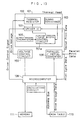
- Fig. 16 is a block diagram showing a prior art embodiment of a thermal head driving device.
- a thermal head 1 has a thermal resistor 2, a driver IC 3 driving the thermal resistor 2 and a thermistor 13 sensing the temperature of the thermal head.
- An A/D converter 4 converts analog temperature data received from the thermistor 13 into digital temperature data to apply it to a microcomputer 7.
- the microcomputer 7 accesses the ROM table 10 to obtain drive pulse width data and applies the drive pulse width data to a pulse width control circuit 5.
- the pulse width control circuit 5 generates a drive pulse signal ( STROBE signal) having its pulse width controlled. In this way, the print density by the thermal head 1 keeps uniform (see International Application No. PCT/US87/01663, for example).
- thermal head driving device must have a considerably large capacity of memory of a circuit for externally driving the thermal head and considerably large amount of control program of the microcomputer, and further requires an expensive A/D converter in view of a digital processing of the microcomputer. Additionally, with a control system of a drive pulse for a thermal resistor provided in the thermal head, there arises the problem that the size of the thermal head is considerably increased.
- the present invention provides a thermal head comprising a substrate, a plurality of thermal resistance elements formed on the substrate corresponding to print dots, driving means for applying pulse voltage to the thermal resistance elements corresponding to print data, temperature sensing means provided on the substrate for sensing the temperature of the substrate, and analog controlling means provided on the substrate and receiving an output from the temperature sensing means for controlling the pulse voltage, so as to unify the print characteristic of the thermal resistance elements.
- the peak value of the drive pulse may be controlled inside the thermal head in accordance with the temperature of the thermal head, while the pulse width of the drive pulse may be controlled in accordance with other factors outside the thermal head, or the pulse width may be controlled inside the thermal head, while the peak value of the drive pulse may be controlled outside the same.
- the thermal head has 500 to 5000 thermal resistors linearly disposed on an insulating substrate usually made of ceramic or the like excellent in resisting property and flatness, each of which is preferably formed so that it can output pixels.
- the temperature sensing means may be a thermistor manufactured by mixing Fe O with solid solution of MgCr2O4 or MgAl2O4 , NiO, Mn2O3 and CO2O3 and sintered them altogether.
- the temperature sensing means is preferably placed close to the thermal resistors so as to sense the temperature of the thermal head and converted into a resistance value.
- control means for controlling the peak value of the drive pulse As control means for controlling the peak value of the drive pulse, a 4-terminal regulator of which output voltage varies in accordance with a variation in resistance (e.g., PQ3ORV manufactured by Sharp Corporation) is desirable in that it is cheap and simple in its circuit configuration. If drive pulse width control means should be place inside the thermal head, that which has a voltage comparator of which difference voltage varies in accordance with the variation in resistance is used to convert a sawtooth-formed integrating wave into a square wave for a pulse control is desirable in that it is cheap and simple in its circuit configuration.
- PQ3ORV manufactured by Sharp Corporation
- FIG. 1 is a block diagram showing a first embodiment according to the present invention.
- a thermal head 101 comprises a plurality of thermal resistors 102, a plurality of driver ICs 103 driving the thermal resistors 102, a thermistor 105 sensing a temperature of the thermal head 101 and a voltage control circuit 104 for controlling voltage VH driving the thermal resistors 102.
- print data processed by a main CPU is parallel data (e.g., eight bit data)
- the parallel print transferred from the main CPU is converted into serial print data by a parallel/serial converter 106
- the serial print data is transferred to the driver ICs 103 provided in the thermal head 101 along with a driver control signal.
- Fig. 2 is a basic circuit diagram of one of the driver ICs 103 shown in Fig. 1.
- the driver IC 103 includes drivers (inverters) 201 made of transistors, a gate circuit 202, a latch circuit 203, a shift register 204 and an output protection circuit 205.
- a signal applied to the driver IC 103 is composed of serial print data (inputted from a DATAIN terminal), a driver control signal (a B.E.O signal, a LATCH signal and a CLOCK signal) and a STROBE signal.
- thermistor 105 is used for converting a variation in resistance of the thermistor 105 into a voltage (the peak value of a pulse) variation using a direct current-output voltage-stabilizing 4-terminal regulator IC in which an arbitrary direct current output voltage can be set by external resistance, as shown in Fig. 4.
- serial print data inputted to a DATAIN terminal 209 is synchronized with a CLOCK signal inputted to a CLOCK terminal 210 to send it to a shift register 204.
- a LATCH pulse signal inputted to a LATCH terminal 208 permits a latch circuit 203 to latch the serial print data in the shift register 204.
- a B.E.O signal makes a B.E.O terminal 206 turn to "HIGH” so that the driver 201 can start, and thereafter a STROBE signal of a drive pulse inputted through a STROBE terminal 207 starts up the thermal resistors 102 to turn on or off STROBE 1 to STROBE 8 , respectively, as shown in Fig. 3. Finally, the B.E.O terminal 206 is turned back to "LOW", and thus a single line printing is completed.
- Fig. 4 is a connection diagram of the voltage control circuit 104 employed in this embodiment.
- a 4-terminal regulator e.g., PQ3ORV manufactured by Sharp Corporation
- RG has reference voltage and a comparator inside it, and output voltage V0 is determined by an external resistance R1 and the thermistor 105.
- VIN denotes input voltage (e.g., DC24V) supplied from the outside of the thermal head 101
- C1 to C3 denote external capacitors.
- Fig. 5 is a graph showing a variation in the output voltage V0 related to a resistance value Rth of the thermistor 105 when resistance R1 is 390 ⁇ is satisfied.
- Fig. 6 represents a temperature characteristic of the thermistor 105 (Fig. 1), where as the temperature rises, the resistance value Rth of the thermistor 105 falls.
- a voltage control circuit is provided in the thermal head to control drive voltage (the peak value) related to temperature, and other external factors control the pulse width.
- a pulse width control circuit is provided inside the thermal head to control pulse width depending on temperature, and other external factors drive voltage will be described below.
- a pulse width control circuit 701 provided in the thermal head, and drive voltage VH is controlled by a voltage control circuit 702 outside of the thermal head.
- the remaining part is equivalent to the embodiment shown in Fig. 1.
- the pulse width control circuit 701 is composed of an integral circuit 802 consisting of a capacitor C, a resistance R and a diode D and a voltage comparing circuit 801 consisting of a resistance R0, a thermistor 105 and a comparator CP, as shown in Fig. 8.
- the reference voltage Vth of the comparator CP is varied in accordance with a variation in the resistance value Rth of the thermistor 105, a drive pulse width tp varies.
- FIG. 9 shows waveforms in points (A), (B) and (C) of the circuit shown in Fig. 8.
- the strobe signal of negative logic is shaped by the pulse width control circuit 701, and thereafter it is inputted to a STROBE terminal 207 of the driver IC 103.
- the resistance value Rth of the thermistor 105 falls, and the reference voltage Vth of the voltage comparing circuit 101 falls.
- This causes an output pulse width tp to get larger, that is, causes a pulse width Th of the negative logic to get smaller, whereby the print density can be unified related to the temperature.
- the drive voltage control or the drive pulse width pulse control can be performed through a temperature variation independently inside the thermal head. Additionally, externally controlling the drive pulse width or the drive pulse voltage as required, energy supplied to the thermal resistor can be controlled.
- FIG. 10 is a block diagram showing an this embodiment.
- a thermal head 101 comprises a plurality of thermal resistors 102, a dummy resistance 112 formed on the same substrate through the same manufacturing process, a plurality of driver ICs 103 driving the thermal resistors 102, a thermistor 105 sensing the temperature of the thermal head 101 and a voltage control circuit 104a for controlling voltage VH driving the thermal resistors 102.
- the resistance 112 is formed of the same material as the resistors 102.
- Fig. 11 is a connection diagram showing the voltage control circuit 104a employed in this embodiment.
- a 4-terminal regulator PQ30RV manufactured by Sharp Corporation which is the same as that employed in the first embodiment has reference voltage and a comparator inside it, and its output votlage is determined depending on an external resistance.
- VIN denotes DC voltage applied from the outside of the thermal head 101.
- C1 to C3 denote external capacitors, wile R0 denotes a resistance.
- the dummy resistance 112 is not necessarily the same as one of the thermal resistors 102 in shape, for example, it may be manufactured with a reference of Rd ( ⁇ ).
- the resistance value Rth of the thermistor 105 increases, but when the resistance value Rd of the dummy resistance 112 increases, the output voltage V0, or the drive voltage VH of the thermal resistors, rises.
- the temperature characteristic of the thermistor 105 is equivalent to that shown in Fig. 6, and hence as the temperature rises, the resistance value falls.
- the drive voltage VH rises when the resistance value Rd of the dummy resistance 112 is large, and then energy applied to the thermal resistors 102 gets larger.
- the resistance value of the thermistor 105 is small on the basis of the applied energy, or when the temperature of thermal head rises, the drive voltage VH falls, and the energy applied to the thermal resistors 102 decreases, so that the print density can keep uniform related to the unevenness of the resistance values of the thermal resistors peculiar to the thermal heads or the temperature variation of the thermal head.
- a voltage control circuit is provided inside the thermal head to control drive voltage corresponding to the resistance value of the thermal resistors and temperature of the thermal head, and external factors other than the above-mentioned resistance value and temperature (e.g., print cycle, the number of print dots in a single line and the like) control a pulse width.
- a pulse width control circuit is provided inside the thermal head to perform the pulse width control corresponding to the resistance values of the thermal resistors and the temperature of the thermal head, and external factors other than the above-mentioned resistance values and temperature control the drive voltage
- a pulse width control circuit 701a controlling a width of the STROBE signal in Fig. 3 is provided inside the thermal head 101, drive voltage VH is controlled by a voltage control circuit 702 outside the thermal head.
- the remaining part of this structure is equivalent to that of the block diagram in Fig. 7.
- the pulse width control circuit 701a is composed of an integral circuit 802 consisting of a resistance R, a capacitor C and a diode D and a voltage comparing circuit 801 consisting of a comparator P, as shown in Fig. 14.
- the reference voltage Vth of the comparator P is varied in accordance with the resistance Rth of the thermistor 105, and a drive pulse width tp varies.
- Fig. 15 shows voltage waveforms in points (A), (B) and (C) in Fig. 14. As can be seen, as the voltage Vth rises, the output pulse width tp becomes small.
- the drive pulse width tp becomes further smaller, and the negative logic pulse width tn becomes smaller.
- a strobe signal of the negative logic is shaped by a pulse width control circuit 701, and thereafter it is inputted to a STROBE terminal 207 of the driver IC 103.
- a dummy resistance and a relatively simple circuit makes it possible that inside a thermal head, the drive voltage control or the drive pulse control can be independently performed outside the thermal head corresponding to a resistance value and temperature of its own thermal resistor. Additionally, externally controlling the drive pulse width and the drive voltage at the same time as required, the print density can be unified.
Applications Claiming Priority (4)
| Application Number | Priority Date | Filing Date | Title |
|---|---|---|---|
| JP219200/89 | 1989-08-25 | ||
| JP1219200A JPH0832464B2 (ja) | 1989-08-25 | 1989-08-25 | サーマルヘッド駆動システム |
| JP26053089A JP2547862B2 (ja) | 1989-10-04 | 1989-10-04 | サーマルヘッド駆動装置 |
| JP260530/89 | 1989-10-04 |
Publications (2)
| Publication Number | Publication Date |
|---|---|
| EP0420412A1 true EP0420412A1 (de) | 1991-04-03 |
| EP0420412B1 EP0420412B1 (de) | 1994-04-13 |
Family
ID=26522976
Family Applications (1)
| Application Number | Title | Priority Date | Filing Date |
|---|---|---|---|
| EP90309288A Expired - Lifetime EP0420412B1 (de) | 1989-08-25 | 1990-08-23 | Wärmekopf |
Country Status (3)
| Country | Link |
|---|---|
| US (1) | US5121135A (de) |
| EP (1) | EP0420412B1 (de) |
| DE (1) | DE69008096T2 (de) |
Cited By (1)
| Publication number | Priority date | Publication date | Assignee | Title |
|---|---|---|---|---|
| EP0730972A2 (de) * | 1995-03-07 | 1996-09-11 | Francotyp-Postalia Aktiengesellschaft & Co. | Druckkopfthermosteuerung |
Families Citing this family (4)
| Publication number | Priority date | Publication date | Assignee | Title |
|---|---|---|---|---|
| US5223853A (en) * | 1992-02-24 | 1993-06-29 | Xerox Corporation | Electronic spot size control in a thermal ink jet printer |
| US7133153B2 (en) | 2000-08-31 | 2006-11-07 | Canon Kabushiki Kaisha | Printhead having digital circuit and analog circuit, and printing apparatus using the same |
| TWI313226B (en) * | 2006-12-21 | 2009-08-11 | Lite On Technology Corp | Voltage adjusting system and method for adjusting driving voltage of thermal print head |
| US20080297582A1 (en) * | 2007-05-28 | 2008-12-04 | Ming-Jiun Hung | Thermal printing apparatus and printing method thereof |
Citations (5)
| Publication number | Priority date | Publication date | Assignee | Title |
|---|---|---|---|---|
| DE1964389A1 (de) * | 1968-12-31 | 1970-07-23 | Texas Instruments Inc | Elektronisches Wiedergabegeraet |
| US3577137A (en) * | 1968-12-31 | 1971-05-04 | Texas Instruments Inc | Temperature compensated electronic display |
| DE3327904A1 (de) * | 1982-08-05 | 1984-02-09 | Canon K.K., Tokyo | Thermoaufzeichnungsgeraet |
| EP0112474A2 (de) * | 1982-12-27 | 1984-07-04 | International Business Machines Corporation | Temperaturüberwachung für Thermodruckkopf |
| US4688051A (en) * | 1983-08-15 | 1987-08-18 | Ricoh Company, Ltd. | Thermal print head driving system |
Family Cites Families (8)
| Publication number | Priority date | Publication date | Assignee | Title |
|---|---|---|---|---|
| US3725898A (en) * | 1971-05-03 | 1973-04-03 | Texas Instruments Inc | Temperature compensated multiple character electronic display |
| DE2928304C2 (de) * | 1978-07-18 | 1983-01-13 | Oki Electric Industry Co., Ltd., Tokyo | Steuerschaltung zum Aufrechterhalten einer konstanten Farbintensität bei einer thermischen Aufzeichnungsvorrichtung |
| JPS60143981A (ja) * | 1983-12-29 | 1985-07-30 | Konishiroku Photo Ind Co Ltd | サ−マルプリンタ |
| JPS60184860A (ja) * | 1984-03-03 | 1985-09-20 | Fujitsu Ltd | サーマルヘッド制御方法 |
| JPS60244564A (ja) * | 1984-05-18 | 1985-12-04 | Konishiroku Photo Ind Co Ltd | サ−マルプリンタ |
| JPS615960A (ja) * | 1984-06-20 | 1986-01-11 | Ricoh Co Ltd | 非安定化電源を用いた感熱記録方式 |
| JPH0632942B2 (ja) * | 1985-09-25 | 1994-05-02 | 株式会社日立製作所 | 記録濃度制御装置 |
| US4866508A (en) * | 1986-09-26 | 1989-09-12 | General Electric Company | Integrated circuit packaging configuration for rapid customized design and unique test capability |
-
1990
- 1990-08-13 US US07/566,626 patent/US5121135A/en not_active Expired - Fee Related
- 1990-08-23 EP EP90309288A patent/EP0420412B1/de not_active Expired - Lifetime
- 1990-08-23 DE DE69008096T patent/DE69008096T2/de not_active Expired - Fee Related
Patent Citations (5)
| Publication number | Priority date | Publication date | Assignee | Title |
|---|---|---|---|---|
| DE1964389A1 (de) * | 1968-12-31 | 1970-07-23 | Texas Instruments Inc | Elektronisches Wiedergabegeraet |
| US3577137A (en) * | 1968-12-31 | 1971-05-04 | Texas Instruments Inc | Temperature compensated electronic display |
| DE3327904A1 (de) * | 1982-08-05 | 1984-02-09 | Canon K.K., Tokyo | Thermoaufzeichnungsgeraet |
| EP0112474A2 (de) * | 1982-12-27 | 1984-07-04 | International Business Machines Corporation | Temperaturüberwachung für Thermodruckkopf |
| US4688051A (en) * | 1983-08-15 | 1987-08-18 | Ricoh Company, Ltd. | Thermal print head driving system |
Cited By (3)
| Publication number | Priority date | Publication date | Assignee | Title |
|---|---|---|---|---|
| EP0730972A2 (de) * | 1995-03-07 | 1996-09-11 | Francotyp-Postalia Aktiengesellschaft & Co. | Druckkopfthermosteuerung |
| EP0730972A3 (de) * | 1995-03-07 | 1996-12-27 | Francotyp Postalia Ag | Druckkopfthermosteuerung |
| US5838356A (en) * | 1995-03-07 | 1998-11-17 | Francotyp-Postalia Ag & Co. | Print head thermocontrol |
Also Published As
| Publication number | Publication date |
|---|---|
| EP0420412B1 (de) | 1994-04-13 |
| DE69008096T2 (de) | 1994-10-13 |
| US5121135A (en) | 1992-06-09 |
| DE69008096D1 (de) | 1994-05-19 |
Similar Documents
| Publication | Publication Date | Title |
|---|---|---|
| EP0421353A2 (de) | Steuervorrichtung für Thermodrucker | |
| EP0562626B1 (de) | Thermodruckkopf dessen Heizelemente mit Stromsensoren ausgerüstet sind | |
| US4510505A (en) | Thermal printer | |
| US5642148A (en) | Thermal head apparatus with integrated circuits and current detection | |
| US5121135A (en) | Thermal head having integral analog drive compensation | |
| JP2547862B2 (ja) | サーマルヘッド駆動装置 | |
| US4928110A (en) | Thermal recording control method and system | |
| JPH0832464B2 (ja) | サーマルヘッド駆動システム | |
| JPH0369714B2 (de) | ||
| JPH06198944A (ja) | 動作パラメータの変動を補償するための改良されたサーマルプリンタシステムおよびその方法 | |
| EP0415718B1 (de) | Wärmekopf | |
| JPS627497Y2 (de) | ||
| JP3202331B2 (ja) | 中間調記録装置 | |
| JP2562379B2 (ja) | サーマルプリンタの駆動制御装置 | |
| JPH0473166A (ja) | サーマルプリンタの駆動制御装置 | |
| JPH02295764A (ja) | サーマルヘッド駆動装置 | |
| JPH08318633A (ja) | 印字ヘッド駆動回路 | |
| JPS6351102B2 (de) | ||
| JPH03120052A (ja) | サーマルプリンタの駆動制御装置 | |
| JPH03126564A (ja) | サーマルプリンタの駆動制御装置 | |
| JPS63295278A (ja) | サ−マルプリンタのヘッド駆動制御装置 | |
| JPH0679904A (ja) | ビデオプリンタ装置 | |
| JPS6015175A (ja) | サ−マルヘツド駆動方式 | |
| JPH0596771A (ja) | 熱転写記録装置の階調制御回路 | |
| JPH0615858A (ja) | サーマルヘッド用駆動回路およびサーマルヘッド |
Legal Events
| Date | Code | Title | Description |
|---|---|---|---|
| PUAI | Public reference made under article 153(3) epc to a published international application that has entered the european phase |
Free format text: ORIGINAL CODE: 0009012 |
|
| 17P | Request for examination filed |
Effective date: 19900914 |
|
| AK | Designated contracting states |
Kind code of ref document: A1 Designated state(s): DE FR GB |
|
| 17Q | First examination report despatched |
Effective date: 19930210 |
|
| RAP1 | Party data changed (applicant data changed or rights of an application transferred) |
Owner name: SHARP KABUSHIKI KAISHA |
|
| GRAA | (expected) grant |
Free format text: ORIGINAL CODE: 0009210 |
|
| AK | Designated contracting states |
Kind code of ref document: B1 Designated state(s): DE FR GB |
|
| REF | Corresponds to: |
Ref document number: 69008096 Country of ref document: DE Date of ref document: 19940519 |
|
| ET | Fr: translation filed | ||
| PLBE | No opposition filed within time limit |
Free format text: ORIGINAL CODE: 0009261 |
|
| STAA | Information on the status of an ep patent application or granted ep patent |
Free format text: STATUS: NO OPPOSITION FILED WITHIN TIME LIMIT |
|
| 26N | No opposition filed | ||
| PGFP | Annual fee paid to national office [announced via postgrant information from national office to epo] |
Ref country code: GB Payment date: 19980814 Year of fee payment: 9 Ref country code: FR Payment date: 19980814 Year of fee payment: 9 |
|
| PGFP | Annual fee paid to national office [announced via postgrant information from national office to epo] |
Ref country code: DE Payment date: 19980831 Year of fee payment: 9 |
|
| PG25 | Lapsed in a contracting state [announced via postgrant information from national office to epo] |
Ref country code: GB Free format text: LAPSE BECAUSE OF NON-PAYMENT OF DUE FEES Effective date: 19990823 |
|
| GBPC | Gb: european patent ceased through non-payment of renewal fee |
Effective date: 19990823 |
|
| PG25 | Lapsed in a contracting state [announced via postgrant information from national office to epo] |
Ref country code: FR Free format text: LAPSE BECAUSE OF NON-PAYMENT OF DUE FEES Effective date: 20000428 |
|
| PG25 | Lapsed in a contracting state [announced via postgrant information from national office to epo] |
Ref country code: DE Free format text: LAPSE BECAUSE OF NON-PAYMENT OF DUE FEES Effective date: 20000601 |
|
| REG | Reference to a national code |
Ref country code: FR Ref legal event code: ST |