EP0420018A2 - Dispositif pour l'amenée de boîtes arrondies à une unité de soudage - Google Patents
Dispositif pour l'amenée de boîtes arrondies à une unité de soudage Download PDFInfo
- Publication number
- EP0420018A2 EP0420018A2 EP90117976A EP90117976A EP0420018A2 EP 0420018 A2 EP0420018 A2 EP 0420018A2 EP 90117976 A EP90117976 A EP 90117976A EP 90117976 A EP90117976 A EP 90117976A EP 0420018 A2 EP0420018 A2 EP 0420018A2
- Authority
- EP
- European Patent Office
- Prior art keywords
- conveying direction
- bodies
- driving
- rocker
- longitudinal
- Prior art date
- Legal status (The legal status is an assumption and is not a legal conclusion. Google has not performed a legal analysis and makes no representation as to the accuracy of the status listed.)
- Granted
Links
Images

Classifications
-
- B—PERFORMING OPERATIONS; TRANSPORTING
- B23—MACHINE TOOLS; METAL-WORKING NOT OTHERWISE PROVIDED FOR
- B23K—SOLDERING OR UNSOLDERING; WELDING; CLADDING OR PLATING BY SOLDERING OR WELDING; CUTTING BY APPLYING HEAT LOCALLY, e.g. FLAME CUTTING; WORKING BY LASER BEAM
- B23K37/00—Auxiliary devices or processes, not specially adapted to a procedure covered by only one of the preceding main groups
- B23K37/04—Auxiliary devices or processes, not specially adapted to a procedure covered by only one of the preceding main groups for holding or positioning work
- B23K37/053—Auxiliary devices or processes, not specially adapted to a procedure covered by only one of the preceding main groups for holding or positioning work aligning cylindrical work; Clamping devices therefor
-
- B—PERFORMING OPERATIONS; TRANSPORTING
- B23—MACHINE TOOLS; METAL-WORKING NOT OTHERWISE PROVIDED FOR
- B23K—SOLDERING OR UNSOLDERING; WELDING; CLADDING OR PLATING BY SOLDERING OR WELDING; CUTTING BY APPLYING HEAT LOCALLY, e.g. FLAME CUTTING; WORKING BY LASER BEAM
- B23K26/00—Working by laser beam, e.g. welding, cutting or boring
- B23K26/20—Bonding
- B23K26/21—Bonding by welding
- B23K26/24—Seam welding
- B23K26/26—Seam welding of rectilinear seams
- B23K26/262—Seam welding of rectilinear seams of longitudinal seams of tubes
Definitions
- the invention relates to a device for feeding rounded can bodies into the area of a welding unit, under the action of which the longitudinal edges of the can bodies are connected to one another via a longitudinal seam, with a forearm extending in the conveying direction and a rail attached to the latter, in the longitudinal grooves of which the longitudinal edges are guided , with a circumferential transport unit held above the can bodies with drivers which are movably fastened to the transport unit about swivel axes arranged transversely to the conveying direction and are supported on a guide track facing the transport unit via a control surface.
- the drivers distributed evenly over the circumference of the transport unit have driver surfaces which, when entering the driving section of the transport unit, can be brought into contact with the longitudinal edges on the back of a can frame and run perpendicular to the conveying direction.
- the guideway is formed on its side corresponding to the driving section in such a way that the driving surfaces temporarily maintain their position perpendicular to the conveying direction even when they leave the driving section.
- the transport unit is composed of two endless chains arranged parallel to one another; the entrained with them, designed as pawls are each arranged at a distance from each other that is greater than the length of the can body in the conveying direction.
- the drivers of both endless chains face each other in pairs on a plane that is aligned exactly at right angles with respect to both endless chains. Only under this condition can the longitudinal edges of the can bodies be welded to each other without any offset, with the result that the end faces (i.e.
- the front and the back) of the can bodies are each exactly in a plane perpendicular to the longitudinal axis of the can body and, accordingly, the bases and lids later free of faults as well can be attached tightly.
- the position of the two endless chains can be influenced by means of steplessly adjustable couplings in such a way that the drivers which belong together in pairs lie exactly opposite one another in the area of the chain wheels.
- this does not yet ensure that the can bodies reach the effective area of the welding unit in a state in which their longitudinal edges lie against one another without a longitudinal offset.
- the can bodies can only be moved according to the chain pitch; it is therefore not possible to feed the can bodies with the desirable minimum distance (preferably at most one millimeter) to the effective area of the welding unit, so that the achievable welding speed cannot be converted into the greatest possible weld seam length.
- the invention is based on the object of designing a device of the type mentioned at the outset in such a way that can bodies with a high number of cycles can be fed to the effective range of a welding unit, preferably a laser welding unit, without displacement. If necessary, the device should also be designed so that the successive can bodies are up to one run as close as possible to each other in the effective range of the welding unit, ie preferably have a mutual distance on the order of less than one millimeter.
- the object is achieved by a device with the features of claim 1.
- the concept of the solution which differs fundamentally from the prior art, consists in constructing the transport unit only from a rotating element and in each case in designing the drivers as a one-piece rocker arm which has two feed pins on its front side pointing in the conveying direction as driving surface; In the driving position, these are able to support the can frame in question on both sides (ie left and right) next to the longitudinal edges.
- one of the rocker arms can have a control arm which extends beyond the pivot axis of the rocker and to which a control surface which is in contact with the guideway is attached.
- the invention is based on the finding that the sum of the tolerances between the advancing pins of the drivers must be zero, that the drivers must be attached to a circulating element that is as uniform as possible and that only a centrally arranged circulating element may be used so that the input mentioned deviations or errors can not have an effect as misalignment.
- the circulating element is preferably arranged and designed in such a way that under its action each can frame is carried along in the conveying direction until part of the longitudinal seam - preferably with a length of up to several millimeters - is present (claim 2).
- the driving section of the circulating element should be dimensioned with respect to the position of the welding unit so that the longitudinal seam produced has a length of between 1 and 3 mm before the feed pins are released from the can frame in question.
- rocker - seen in the side view - is angular and - seen in plan view - U-shaped (claim 3).
- the mutual spacing of the feed pins can be smaller than that of the swing arm (claim 4).
- the circulating element can be adjusted by means of a switching unit with respect to the feed chain drives in such a way that its rockers have a lead of the order of magnitude in relation to the driving tines moving in the same direction have up to several millimeters, preferably between 1 to 2 mm (claim 5).
- the lead for example brought about by means of a continuously adjustable clutch, has the consequence that the can bodies are detached from the driving tines of the side chain drives.
- feed chain drives which are expediently attached on the right and left at the level of the longitudinal axis or transverse plane of the can bodies, is known for example from DE-PS 36 15 706.
- the lateral feed chain drives can be designed in such a way that they extend in the conveying direction over the area of the welding unit and counter to the conveying direction beyond the area of the revolving unit (claim 6); in this case the driving section of the feed chain drives is in any case dimensioned considerably longer than that of the centrally arranged revolving element.
- the feed chain drives can also be arranged in such a way that their rear end section (opposite the conveying movement) lies in the outlet area of the circulating element (claim 7); in this case, the feed chain drives only serve to convey the can bodies out of the effective range of the welding unit and, if appropriate, to a further processing station which follows, for example wise to supply a seam coating unit.
- the rotating element in the conveying direction can also be assigned two pairs of friction rollers in succession in the direction of conveyance with a driven top roller, the first pair of friction rollers being arranged in front of and the second pair of friction rollers behind the area of the welding unit and the top roller of the first pair of friction rollers being provided with a one-way clutch (claim 8).
- the speed of the rockers in the conveying direction relative to the circumferential speed of the friction rollers should be greater by the percentage that the mutual distance between the rockers exceeds the length of the can bodies in the conveying direction (claim 9).
- the speed of the detected can frame in the conveying direction drops slightly due to the outward movement of the associated control surface on the guideway until it reaches the transfer point behind the effective area of the welding unit (i.e. after a longitudinal seam has been made in the Order of magnitude of up to several millimeters) corresponds to the peripheral speed of the friction wheel pairs corresponding to the welding speed.
- an embodiment of the subject of the invention is characterized in that the circulating element is designed as an endless chain with bearing blocks on which the rockers are supported via their legs (claim 10).
- the endless chain can in particular be in the form of a link or roller chain, which is supported in a manner known per se at least on a drive wheel and a tensioning wheel.
- the subject matter of the invention can also have a rotating disk as a revolving element, on which the rockers are supported via their legs (claim 11).
- the diameter of this disk can in particular be such that only one rocker arm performs a correspondingly short feed movement in the conveying direction.
- a rotating element in the form of a flexible elastic belt in combination with a parallel guidance of the rockers is also possible.
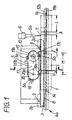
- the can welding machine partially shown in FIG. 1 is used to produce rounded can bodies 1 which are produced in a previous operation and which move from left to right in the conveying direction (arrow 2) and are displaceably supported on a rail 3 with their side edges 1 a, 1 b, by means of two feed chain drives 4 a, 4 b (cf. also FIG. 2) in the area of the driving section (indicated by the length dimension M of a circulating element 5) and via this to the effective area of a welding unit 6; this is generated by means of a bundled laser beam 6 a a longitudinal seam 7 which connects the longitudinal edges 1 a, 1 b of the can bodies to one another in a manner known per se.
- the welded can body in question is again gripped by the feed chain drives 4 a, 4 b and in the conveying direction (arrow 2 ) of further processing, for example in a seam varnish, not shown device, supplied.
- the rail 3 which is attached to the upper side of a forearm 8 which is longer in the conveying direction, has on its front side in the area between the welding unit 6 and the rotating element 5 and on the back of each a mounting plate 3 a or 3 b, which is connected to a frame 10 via a releasable connection 9.
- the rail 3 is designed as a sword rail for butt butt welding, ie it has two longitudinal grooves 3 c, 3 d on its upper side facing the circulating element 5, which lie opposite one another at the same height and in which the longitudinal edge 1 a or 1 b is slidably supported in the conveying direction.
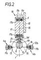
- the feed chain drives 4 a, 4 b each consist of an endless roller chain 11 a or 11 b, which run in a stationary guide cage 12 a or 12 b outside the diameter of the can bodies 1 and have driving tines 13 and 14 at regular intervals. Their length is dimensioned such that they protrude in the area of the feed section of the feed chain drives in the direction of the longitudinal axis 1 c of the can body, that is to say they can detect and advance the can bodies in question (see FIG. 2).
- the guide cages 12 a, 12 b are aligned such that they are opposite each other at a height of the longitudinal axis 1 c in a transverse plane 15; this in turn runs perpendicular to a longitudinal center plane 16 through the rail 3 and the longitudinal axis 1 c.
- roller chain 5 In contrast to the prior art, for the precise alignment and feeding of the can bodies 1 into the effective area of the welding unit 6, there is a single transport unit, namely the aforementioned rotating element in the form of a uniformly rotating, endless roller chain 5, which is at a distance above the rail 3 in one rotates on the frame 10 held base body 17 and the longitudinal center plane coincides with the longitudinal center plane 16.
- the movement game space of the roller chain 5 is defined by a roller conveyor 17 a in the base body (Fig. 2).
- the roller chain 5 has, at regular intervals (corresponding to the division designated T in FIG. 5), bearing blocks 5 a, on which movable drivers are held about pivot axes 5 b. These are - viewed in plan view in the driving position shown in FIG.
- Each rocker arm has two feed pins 18 c, 18 d on its front in the conveying direction as the driving surface, the mutual distance za of which is greater than the rail width sb and smaller than the mutual distance sa of the rocker arms 18 a, 18 b.
- the feed pins 18 c and 18 d are otherwise aligned perpendicular to the legs 18 a and 18 b, so that the rocker 18 - seen in side view - is angular.
- the length of the feed pins 18 c and 18 d is such that they are supported in the driving position on both sides of the longitudinal edges 1 a, 1 b on the back 1 d of the can body 1 to be transported. Due to the fact that the feed pins are a rigid component of a one-piece driver on both sides of the longitudinal edges 1 a, 1 b, the can bodies can be fed to the effective area of the welding unit 6 in a state in which their longitudinal edges lie against one another without a longitudinal offset. The use of the rockers 18 thus ensures that, for example, the plane defined by the rear 1 d of the can frame 1 is exact during the feeding process remains aligned perpendicular to the longitudinal axis 1 c.
- the swing arm 18 b has a control arm 18 e extending beyond the pivot axis 5 b, to which a rounded control surface 18 f is attached; the latter slides during the orbital movement on an outer guideway 17 b of the base body 17 and thereby forces the desired alignment of the rocker 18.
- the roller chain 5 is deflected by means of a drive wheel 19 and a tensioning wheel 20 which rotate counterclockwise around stationary axes 19 a and 20 a; the drive wheel 19 is connected via a continuously adjustable clutch 19 b to a drive, not shown.
- the guide track 17 b On the outlet side, ie in the area of the drive wheel 19, the guide track 17 b has an obliquely running, approximately rectilinear outlet section 17 c. This is designed so that the rockers 18 maintain their driving position in the deflection of the roller chain 5 about the drive wheel 19 over a limited angle of rotation, in which the feed pins are arranged vertically.
- Fig. 1 shows that the mutual distance between successive wings 18, which corresponds to that of successive driving tines 13 and 14, is composed of the length L of the can bodies 1 and their mutual distance A.
- the position of the rockers 18 can be changed in such a way that, with respect to the driving tines 13 and 14, they have a lead V in the conveying direction of the order of almost two millimeters.
- the result of this measure is that the can bodies in question in the area of the driving section M just rest on the rocker 18 and experience the desired exact alignment without misalignment.
- the driving section M is dimensioned and arranged according to the invention in such a way that the can bodies are only released again by the rockers 18 and are conveyed further by the driving tines 13 and 14, when under the action of the laser beam 6 a a longitudinal seam 7 with a length of just under three Millimeters has been produced. In this way it is ensured that the rockers 18 used for exact alignment remain effective until the already existing longitudinal seam excludes the occurrence of an undesired offset between the longitudinal edges 1 a and 1 b of the can body.
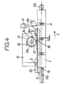
- the revolving element arranged centrally above the rail 3 can also consist of a disk 21 which rotates counterclockwise in a fixed axis 21 a and is connected to a drive (not shown) with the interposition of a continuously adjustable clutch 22 (FIG. 4).
- a continuously adjustable clutch 22 (FIG. 4).
- two rockers 18 are pivotally held on the disk 21 and are aligned in the manner already described by being supported on a guide track 24.
- the mutual spacing of the rockers 18, which are accordingly offset from one another by an angle of 180 °, is such that it is at the mutual spacing of the driving tines 14 (and 13; successive in the conveying direction (arrow 2); see FIG. 2) matches.
- the mode of operation of the embodiment in question coincides with that of FIG. 1 with the additional difference that only one of the two rockers 18 is in engagement with a can frame 1 and this feeds the effective range of the welding unit 6 to the extent that this one Longitudinal seam with a length of the order of a few millimeters can produce.
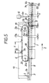
- the revolving element consisting of the roller chain 5 is designed to be considerably longer and accordingly has seven rockers 18, three of which are in engagement with successive can bodies 1.
- the laterally arranged feed chain drives for example the feed chain drive 4 b shown, are arranged in such a way that they extend in the conveying direction (arrow 2) beyond the effective area of the welding unit 6, but their rear end section coincides with the run-out area of the roller chain 5 , in which the rockers 18 are released under the action of the outlet section 17 c from the can bodies 1 in question. Due to its greater longitudinal extent, the roller chain 5 with the associated rockers 18 in take on larger tasks at the same time. The shifting of the feed chain drives in the conveying direction to the right makes it possible to make them shorter under otherwise unchanged working conditions.
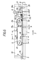
- the embodiment according to FIG. 6 differs essentially only from the previously described embodiment in that the lateral feed chain drives are replaced by two pairs of friction rollers 25, 26 or 27, 28, the top roller 25 or 27 of which is driven and which - in the conveying direction Seen (arrow 2) - lie in front of or behind the welding unit 6.
- the upper roller 25 is additionally equipped with a one-way clutch 25 a; this makes it possible to adapt the peripheral speed of the first pair of friction rollers 25, 26 to the conveying speed which changes during the conveying movement of the can bodies 1.
- the top roller 27 of the second pair of friction rollers is attached to an extension 10 a of the frame 10, the bottom rollers 26 and 28 are each rotatably mounted on the forearm 7.
- the speed of the rockers 18 in the conveying direction relative to the peripheral speed of the friction rollers is set approximately larger by the percentage than the mutual distance of the rockers 18 (pitch T) exceeds the length L of the can bodies 1 in the conveying direction.
- pitch T the percentage than the mutual distance of the rockers 18
- Such a design of the interacting drive components makes it possible to set the distance A in the effective range of the rockers 18 to a minimum value S (of the order of less than 1 mm) in the effective range of the welding unit 6 to reduce.
- the advantage achieved by the invention is in particular that the feed movement of the can bodies to be welded takes place behind the effective area of the welding unit by means of a centrally arranged revolving element, the arms of which can be supported on the can bodies and are formed in one piece with the associated feed pins.
- the driving section over the length of which the can bodies are pushed forward by the rockers, is dimensioned such that a longitudinal seam has already been produced before the wings are released from the can bodies.
- the training in question ensures that the longitudinal edges of the can bodies reach the effective area of the welding unit without offset in the longitudinal direction.
- the feed movement of the can bodies can also be adjusted in such a way that the mutual spacing of successive can bodies is reduced to a minimum value up to the entry into the effective range of the welding unit, so that the achievable welding performance can be used as far as possible.
Landscapes
- Physics & Mathematics (AREA)
- Optics & Photonics (AREA)
- Engineering & Computer Science (AREA)
- Mechanical Engineering (AREA)
- Plasma & Fusion (AREA)
- Chain Conveyers (AREA)
- Automatic Assembly (AREA)
- Pusher Or Impeller Conveyors (AREA)
Applications Claiming Priority (2)
| Application Number | Priority Date | Filing Date | Title |
|---|---|---|---|
| DE3932551A DE3932551C2 (de) | 1989-09-29 | 1989-09-29 | Einrichtung zum Zuführen gerundeter Dosenzargen in den Bereich einer Schweißeinheit |
| DE3932551 | 1989-09-29 |
Publications (3)
| Publication Number | Publication Date |
|---|---|
| EP0420018A2 true EP0420018A2 (fr) | 1991-04-03 |
| EP0420018A3 EP0420018A3 (en) | 1991-07-10 |
| EP0420018B1 EP0420018B1 (fr) | 1994-06-22 |
Family
ID=6390484
Family Applications (1)
| Application Number | Title | Priority Date | Filing Date |
|---|---|---|---|
| EP90117976A Expired - Lifetime EP0420018B1 (fr) | 1989-09-29 | 1990-09-19 | Dispositif pour l'amenée de boîtes arrondies à une unité de soudage |
Country Status (3)
| Country | Link |
|---|---|
| US (1) | US5060840A (fr) |
| EP (1) | EP0420018B1 (fr) |
| DE (2) | DE3932551C2 (fr) |
Cited By (2)
| Publication number | Priority date | Publication date | Assignee | Title |
|---|---|---|---|---|
| EP0623407A1 (fr) * | 1993-05-03 | 1994-11-09 | Krupp Maschinentechnik Gesellschaft Mit Beschränkter Haftung | Dispositif pour placer verticalement des corps de boîte |
| CN111421259A (zh) * | 2020-04-12 | 2020-07-17 | 辽宁科技大学 | 一种输送辊轴头安装焊接装置及方法 |
Families Citing this family (6)
| Publication number | Priority date | Publication date | Assignee | Title |
|---|---|---|---|---|
| EP0743135B1 (fr) * | 1995-05-15 | 1999-07-14 | Elpatronic Ag | Procédé de jonction de deux pièces |
| EP1080819A3 (fr) * | 1999-09-03 | 2003-02-12 | Elpatronic Ag | Méthode d'alimentation d'une machine de soudage, ainsi qu'appareil d'alimentation automatique pour la mise en oeuvre |
| MXPA02003774A (es) * | 1999-10-22 | 2002-09-30 | Elpatronic Ag | Metodo y dispositivo para la formacion de tubos. |
| DE102007018387B4 (de) * | 2007-04-17 | 2014-09-04 | Weil Engineering Gmbh | Durchlaufschweißmaschine zum Verschweißen eines Rohrrohlings |
| CN101468430B (zh) * | 2007-12-28 | 2011-05-18 | 中国科学院沈阳自动化研究所 | 一种新型gis控制柜激光焊接拼装夹具 |
| CN106736073A (zh) * | 2016-12-23 | 2017-05-31 | 安徽普伦智能装备有限公司 | 一种自动上料焊接机 |
Citations (2)
| Publication number | Priority date | Publication date | Assignee | Title |
|---|---|---|---|---|
| EP0273135A1 (fr) * | 1986-12-09 | 1988-07-06 | Elpatronic Ag | Procédé et installation pour l'orientation et le déplacement longitudinal de corps arrondis de boîte relativement à un appareil de soudage |
| US4774391A (en) * | 1985-08-21 | 1988-09-27 | Elpatronic Ag | Machine for welding together the longitudinal edges of rounded can bodies |
Family Cites Families (8)
| Publication number | Priority date | Publication date | Assignee | Title |
|---|---|---|---|---|
| US2846972A (en) * | 1956-08-21 | 1958-08-12 | American Can Co | Apparatus for supporting treating devices inside moving can bodies |
| US3255945A (en) * | 1964-02-03 | 1966-06-14 | United Shoe Machinery Corp | Side seam soldering machines |
| DD55293A1 (de) * | 1966-07-01 | 1967-04-05 | Wolfgang Schoeps | Vorrichtung zum Fördern von mit keramischem Gut besetzten Tragplatten auf einer Gleitbahn |
| CH598905A5 (fr) * | 1976-11-09 | 1978-05-12 | Fael Sa | |
| CH621499A5 (fr) * | 1977-06-10 | 1981-02-13 | Paul Opprecht | |
| CH669921A5 (fr) * | 1986-04-22 | 1989-04-28 | Elpatronic Ag | |
| CH671945A5 (fr) * | 1987-05-07 | 1989-10-13 | Elpatronic Ag | |
| DE3720804A1 (de) * | 1987-06-24 | 1989-01-12 | Krupp Gmbh | Transporteinrichtung fuer gerundete dosenzargen |
-
1989
- 1989-09-29 DE DE3932551A patent/DE3932551C2/de not_active Expired - Fee Related
-
1990
- 1990-09-19 DE DE59006206T patent/DE59006206D1/de not_active Expired - Fee Related
- 1990-09-19 EP EP90117976A patent/EP0420018B1/fr not_active Expired - Lifetime
- 1990-09-28 US US07/589,632 patent/US5060840A/en not_active Expired - Fee Related
Patent Citations (2)
| Publication number | Priority date | Publication date | Assignee | Title |
|---|---|---|---|---|
| US4774391A (en) * | 1985-08-21 | 1988-09-27 | Elpatronic Ag | Machine for welding together the longitudinal edges of rounded can bodies |
| EP0273135A1 (fr) * | 1986-12-09 | 1988-07-06 | Elpatronic Ag | Procédé et installation pour l'orientation et le déplacement longitudinal de corps arrondis de boîte relativement à un appareil de soudage |
Non-Patent Citations (1)
| Title |
|---|
| PATENT ABSTRACTS OF JAPAN vol. 13, no. 225 (M-830)(3573) 25 Mai 1989, & JP-A-1 40193 (TOKYO SEIKAN KAISHA) 10 Februar 1989, * |
Cited By (5)
| Publication number | Priority date | Publication date | Assignee | Title |
|---|---|---|---|---|
| EP0623407A1 (fr) * | 1993-05-03 | 1994-11-09 | Krupp Maschinentechnik Gesellschaft Mit Beschränkter Haftung | Dispositif pour placer verticalement des corps de boîte |
| US5423410A (en) * | 1993-05-03 | 1995-06-13 | Krupp Maschinentechnik Gmbh | Conveying device for vertically positioning can bodies |
| DE4314462C2 (de) * | 1993-05-03 | 2001-02-08 | Krupp Kunststofftechnik Gmbh | Vorrichtung zum Senkrechtstellen von Dosenzargen |
| CN111421259A (zh) * | 2020-04-12 | 2020-07-17 | 辽宁科技大学 | 一种输送辊轴头安装焊接装置及方法 |
| CN111421259B (zh) * | 2020-04-12 | 2024-02-09 | 辽宁科技大学 | 一种输送辊轴头安装焊接装置及方法 |
Also Published As
| Publication number | Publication date |
|---|---|
| DE59006206D1 (de) | 1994-07-28 |
| EP0420018B1 (fr) | 1994-06-22 |
| US5060840A (en) | 1991-10-29 |
| EP0420018A3 (en) | 1991-07-10 |
| DE3932551A1 (de) | 1991-04-11 |
| DE3932551C2 (de) | 1998-07-09 |
Similar Documents
| Publication | Publication Date | Title |
|---|---|---|
| DE60118948T2 (de) | Überführung von gegenständen zwischen entgegengesetzt angetriebenen förderern | |
| DE3621357C1 (de) | Kappsaege zum Ablaengen von Brettern | |
| CH660991A5 (de) | Einrichtung zum montieren bzw. bearbeiten von werkstuecken. | |
| DE2714973C2 (de) | Vorrichtung zum Vorschieben von Rohbrettern zu einer Kantenbesäumsäge | |
| DE4006312A1 (de) | Fertigungsanlage zum bearbeiten und montieren von bauteilen | |
| DE4402560C2 (de) | Vorrichtung zum Drehen von flachliegend voranbewegten Werkstücken | |
| CH671945A5 (fr) | ||
| EP0420018B1 (fr) | Dispositif pour l'amenée de boîtes arrondies à une unité de soudage | |
| DE1506905B2 (de) | Fördervorrichtung mit Rollen | |
| DE3523901A1 (de) | Glasplattenschleifmaschine | |
| DE174491C (fr) | ||
| DE1150021B (de) | Foerdervorrichtung mit in verstellbaren Abstaenden sich folgenden Mitnahmeorganen | |
| DE2122990C3 (de) | Maschine zum Bearbeiten der Kanten von Glasscheiben o.dgl. | |
| DE1627338C3 (de) | Fur eine Verzahnungsmaschine o dgl bestimmter Werkstuckförderer | |
| EP0212620B1 (fr) | Machine pour souder ensemble les bords longitudinaux de pièces brutes de boîtes arrondies | |
| DE8033556U1 (de) | Vorrichtung zum aufnehmen, zur lageverschiebung und zum stapeln von stabfoermigen gegenstaenden wie stangen und leisten aus holz oder dergleichen (z.b. von profilstaeben fuer bilderrahmen) | |
| DE2142931B2 (de) | Vorrichtung zum aufziehen von querrippen auf ortsfest gelagerte rohre | |
| DE3910524C2 (fr) | ||
| DE608942C (de) | Vorrichtung zum Zufuehren von Schuhen zu aufeinanderfolgenden Arbeitsstellen mittels auf endloser Bahn absatzweise weiterbewegter Wagen | |
| DE3712522C2 (fr) | ||
| DE2644490C3 (de) | Vorrichtung zum Verschieben der Schützen einer Wellenfach-Webmaschine | |
| DE19540177C2 (de) | Fördersystem | |
| DE276291C (fr) | ||
| DE2730864A1 (de) | Foerdereinrichtung | |
| DE1932692A1 (de) | Vorrichtung zum lagenweisen UEbereinanderstapeln von Walzprofilen |
Legal Events
| Date | Code | Title | Description |
|---|---|---|---|
| PUAI | Public reference made under article 153(3) epc to a published international application that has entered the european phase |
Free format text: ORIGINAL CODE: 0009012 |
|
| AK | Designated contracting states |
Kind code of ref document: A2 Designated state(s): AT BE CH DE FR GB IT LI NL SE |
|
| PUAL | Search report despatched |
Free format text: ORIGINAL CODE: 0009013 |
|
| AK | Designated contracting states |
Kind code of ref document: A3 Designated state(s): AT BE CH DE FR GB IT LI NL SE |
|
| 17P | Request for examination filed |
Effective date: 19920107 |
|
| 17Q | First examination report despatched |
Effective date: 19930202 |
|
| GRAA | (expected) grant |
Free format text: ORIGINAL CODE: 0009210 |
|
| AK | Designated contracting states |
Kind code of ref document: B1 Designated state(s): CH DE IT LI |
|
| REF | Corresponds to: |
Ref document number: 59006206 Country of ref document: DE Date of ref document: 19940728 |
|
| ITF | It: translation for a ep patent filed |
Owner name: STUDIO JAUMANN |
|
| EN | Fr: translation not filed | ||
| PLBI | Opposition filed |
Free format text: ORIGINAL CODE: 0009260 |
|
| 26 | Opposition filed |
Opponent name: SOUDRONIC AG Effective date: 19950322 |
|
| RAP2 | Party data changed (patent owner data changed or rights of a patent transferred) |
Owner name: KRUPP KUNSTSTOFFTECHNIK GMBH |
|
| REG | Reference to a national code |
Ref country code: CH Ref legal event code: PFA Free format text: KRUPP MASCHINENFABRIK GESELLSCHAFT MIT BESCHRAENKTER HAFTUNG TRANSFER- KRUPP KUNSTSTOFFTECHNIK GMBH |
|
| PLBO | Opposition rejected |
Free format text: ORIGINAL CODE: EPIDOS REJO |
|
| APAC | Appeal dossier modified |
Free format text: ORIGINAL CODE: EPIDOS NOAPO |
|
| APAE | Appeal reference modified |
Free format text: ORIGINAL CODE: EPIDOS REFNO |
|
| APAC | Appeal dossier modified |
Free format text: ORIGINAL CODE: EPIDOS NOAPO |
|
| APAE | Appeal reference modified |
Free format text: ORIGINAL CODE: EPIDOS REFNO |
|
| APAC | Appeal dossier modified |
Free format text: ORIGINAL CODE: EPIDOS NOAPO |
|
| PLBN | Opposition rejected |
Free format text: ORIGINAL CODE: 0009273 |
|
| STAA | Information on the status of an ep patent application or granted ep patent |
Free format text: STATUS: OPPOSITION REJECTED |
|
| 27O | Opposition rejected |
Effective date: 20010125 |
|
| PGFP | Annual fee paid to national office [announced via postgrant information from national office to epo] |
Ref country code: CH Payment date: 20010816 Year of fee payment: 12 |
|
| PGFP | Annual fee paid to national office [announced via postgrant information from national office to epo] |
Ref country code: DE Payment date: 20010903 Year of fee payment: 12 |
|
| PG25 | Lapsed in a contracting state [announced via postgrant information from national office to epo] |
Ref country code: LI Free format text: LAPSE BECAUSE OF NON-PAYMENT OF DUE FEES Effective date: 20020930 Ref country code: CH Free format text: LAPSE BECAUSE OF NON-PAYMENT OF DUE FEES Effective date: 20020930 |
|
| PG25 | Lapsed in a contracting state [announced via postgrant information from national office to epo] |
Ref country code: DE Free format text: LAPSE BECAUSE OF NON-PAYMENT OF DUE FEES Effective date: 20030401 |
|
| REG | Reference to a national code |
Ref country code: CH Ref legal event code: PL |
|
| PG25 | Lapsed in a contracting state [announced via postgrant information from national office to epo] |
Ref country code: IT Free format text: LAPSE BECAUSE OF NON-PAYMENT OF DUE FEES;WARNING: LAPSES OF ITALIAN PATENTS WITH EFFECTIVE DATE BEFORE 2007 MAY HAVE OCCURRED AT ANY TIME BEFORE 2007. THE CORRECT EFFECTIVE DATE MAY BE DIFFERENT FROM THE ONE RECORDED. Effective date: 20050919 |
|
| APAH | Appeal reference modified |
Free format text: ORIGINAL CODE: EPIDOSCREFNO |
|
| PLAB | Opposition data, opponent's data or that of the opponent's representative modified |
Free format text: ORIGINAL CODE: 0009299OPPO |