EP0418636A2 - Projectile à trajectoire corrigé - Google Patents
Projectile à trajectoire corrigé Download PDFInfo
- Publication number
- EP0418636A2 EP0418636A2 EP19900116937 EP90116937A EP0418636A2 EP 0418636 A2 EP0418636 A2 EP 0418636A2 EP 19900116937 EP19900116937 EP 19900116937 EP 90116937 A EP90116937 A EP 90116937A EP 0418636 A2 EP0418636 A2 EP 0418636A2
- Authority
- EP
- European Patent Office
- Prior art keywords
- projectile
- cover
- detonator
- radially
- charge
- Prior art date
- Legal status (The legal status is an assumption and is not a legal conclusion. Google has not performed a legal analysis and makes no representation as to the accuracy of the status listed.)
- Granted
Links
- 230000005484 gravity Effects 0.000 claims description 9
- 239000011324 bead Substances 0.000 claims description 3
- 230000007704 transition Effects 0.000 claims 1
- 230000000694 effects Effects 0.000 description 5
- 239000007789 gas Substances 0.000 description 4
- 238000006243 chemical reaction Methods 0.000 description 3
- 230000002093 peripheral effect Effects 0.000 description 3
- 230000004913 activation Effects 0.000 description 2
- 238000006073 displacement reaction Methods 0.000 description 2
- 230000001960 triggered effect Effects 0.000 description 2
- 230000001133 acceleration Effects 0.000 description 1
- 238000011161 development Methods 0.000 description 1
- 230000018109 developmental process Effects 0.000 description 1
- 230000010354 integration Effects 0.000 description 1
- 238000012986 modification Methods 0.000 description 1
- 230000004048 modification Effects 0.000 description 1
- 239000012495 reaction gas Substances 0.000 description 1
Images
Classifications
-
- F—MECHANICAL ENGINEERING; LIGHTING; HEATING; WEAPONS; BLASTING
- F42—AMMUNITION; BLASTING
- F42B—EXPLOSIVE CHARGES, e.g. FOR BLASTING, FIREWORKS, AMMUNITION
- F42B10/00—Means for influencing, e.g. improving, the aerodynamic properties of projectiles or missiles; Arrangements on projectiles or missiles for stabilising, steering, range-reducing, range-increasing or fall-retarding
- F42B10/60—Steering arrangements
- F42B10/66—Steering by varying intensity or direction of thrust
- F42B10/661—Steering by varying intensity or direction of thrust using several transversally acting rocket motors, each motor containing an individual propellant charge, e.g. solid charge
Definitions
- the invention relates to a projectile according to the preamble of claim 1.
- Such a projectile is known from DE-PS 22 64 243 as a missile rotating during flight, in which the trajectory can be changed with the aid of at least one pulse which can be triggered during flight and is oriented radially to the missile in order to increase the probability of being hit.
- the impulse is generated with the help of a mass part that can be accelerated by an impulse charge and leads approximately to the parallel displacement out of the current trajectory when it is directed towards the projectile center of gravity.
- Information about the current web deposit with respect to the target receiving or calculating control device determines in which current roll position of the projectile the transverse pulse is triggered, or which of several existing and still available such transverse thrust drive devices distributed around the periphery of the projectile has the most suitable spatial orientation for the required path correction and is therefore to be controlled electrically.
- Kinematically comparable path correction devices based on control nozzle recoil effect are known from EP-PS 0 028 966 or from DE-PS 27 14 688. In the latter case there is a central gas generator for selectively opening gas jet outlets nozzles provided. Each nozzle has a plug that can be screwed into a radial wall opening of the projectile and contains a form-fitting insert with a radially oriented stopper fixed therein within a threaded chuck.
- a detonator which is wired radially to the center of the projectile, acts between the stopper and insert, in order to hollow out the interior of the insert by ejecting the stopper and thus to deform the wall of the now hollow-cylindrical insert so that it is pushed out of the screw thread surround by the gas generator overpressure and so a gas outlet nozzle can be opened. Once an opening is cleared, no more can be opened afterwards.
- a transverse thrust drive device designed in this way has the advantage over an impulse engine of the generic type of being able to have a longer transverse force acting on the projectile; which is particularly undesirable in a projectile stabilized with a high twist, because the transverse thrust direction changes with the self-rotation of the projectile.
- the invention is therefore based on the object of designing a projectile of the generic type in such a way that the strongest possible but precise effects of path correction can be brought into effect.
- a predetermined breaking point which can be designed within wide limits, can be defined for each individual pulse charge, at which overpressure the relatively large mass of the end cover, which does not affect the aerodynamic properties of the projectile in terms of shape, is thrown out transversely and thus supported by Escape of the ignited impulse charge triggers a high-magnitude and very precise, because short reaction impulse on the projectile.
- transverse thrust drive devices offset from the center of gravity cross-section impress a moment around the projectile center of gravity when they are actuated, which leads to a swiveling of the path.
- the design of the transverse thrust drive devices according to the invention with activation of the pulse charge by a detonator engaging radially from the outside provides an optimally rapid conversion of the pulse charge to the reaction gas which, in the interest of high radial acceleration of the lid mass, only attaches its predetermined breaking points when the overpressure is reached under the lid to tear open on the wall structure.
- the predetermined breaking connection of the lid integration can be designed in an integral design of the lid with its mounting element, for example screwed into the lateral surface of the projectile, with a mechanically weakened lid edge zone, but also as a positive connection between the radially flung lid and its mounting element.
- a cavity between the inside of the cover and the pulse charge arranged underneath simplifies the wiring for the electrical connection of the detonator, which engages radially in the pulse charge coaxially under the cover, without substantially reducing the reaction mass of the cover.
- the structure of the projectile can be completely closed towards the inside, so that its centrally arranged parts (such as the warhead and the pulse control circuit) are hermetically sealed against the mechanical and pyrotechnic effect of the ignited pulse charge and are thus optimally protected.
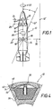
- FIG. 1 shows a projectile 10 with a central longitudinal axis 12 and center of gravity 14. It has a number of transverse thrust drive devices 16 arranged distributed around its circumference. These are arranged in a plane perpendicular to the central longitudinal axis 12, which runs through the center of gravity 14. Further transverse thrust drive devices 18 are arranged in planes 24, 26, which are also oriented perpendicular to the central longitudinal axis 12, but which are at a distance from the center of gravity 14. If one of the drive devices 16 is activated by means of a control device 28 indicated as a block, depending on the swirl 22, an approximately parallel offset 30 of the path of the projectile 10 results in a longitudinal axis 12 'as a result of the recoil effect.
- one of the drive devices 18 is activated with the aid of the control device 28, the longitudinal axis 12 is pivoted, for example, by the angle a in the direction of the longitudinal axis 12 ⁇ . Appropriate activation of one or the other of the drive devices 16, 18 therefore makes it possible to control the trajectory of the projectile 10.
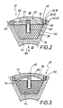
- FIG. 2 shows a partial section through the projectile 10 in the form of a circular ring segment, from which an embodiment of a drive device 16 or 18 can be seen.
- the projectile 10 has a central cavity 32 for receiving a payload, for example an active charge including safety and ignition devices.
- a payload for example an active charge including safety and ignition devices.
- recesses 36 are formed along its circumference in the radial direction from the central cavity 32 of the projectile 10 to its outer side 38. Each recess is provided at its outer end section on a cylindrical depression 40 with an internally threaded section 42.
- a pulse charge 44 is arranged in the recess 36.
- Each recess 36 is closed by means of an associated cover 46, which is pressed here against the impulse charge 44 and which has a circular peripheral edge 48 with an external thread section 50 corresponding to the internal thread section 42. At a distance from the peripheral edge 48, a predetermined breaking point 52 of predetermined tear strength extends around the cover 46.
- circumferential grooves 56, 60 are provided on the outside 54 and on the inside 58 of the cover 46.
- a detonator 62 with an electrical connection cable 64 projects radially from the outside into the pulse charge 44 and is operatively connected to a control device 28 (indicated as a block in FIG. 1).
- a control device 28 (indicated as a block in FIG. 1).
- On the outside 54 of the cover 46 is a mounting window 66 for the connecting cable 61. It can also be seen from FIG. 2 that the outside 54 of the cover 46 has a contour adapted to the outside contour of the projectile 10.
- the detonator 62 is electrically activated via the control device 28 (see FIG. 1), the corresponding pulse charge 44 is ignited. As a result, such a high pressure builds up in the recess 36 closed by the cover 46 that the cover 46 finally tears off along the predetermined breaking section 52 and is flung radially away from the projectile 10. According to the momentum conservation law, this results in a movement of the projectile 10 in the direction of arrow 68.
- Figure 3 shows an embodiment of the projectile 10, which differs from that in Figure 2, in particular in that the inside 58 of the cover 46 does not lie directly on the pulse charge 44, but is concave, so that between the pulse charge 44 and the inside 58 of the cover 46 results in a pressure-absorbing space 70.
- the connecting cable 64 can - contrary to FIG. 2 - be arranged below the cover 46 instead of through the cover 46.
- the cover 46 is only provided on the inside with a circumferential groove 60, while its outside 54 is smooth.
- FIG. 4 shows a third embodiment of the projectile 10 in a partial section corresponding to FIGS. 2 and 3, the cover 46 having a circumferential fastening bead 72 and the cylindrical depression 40 of the recess 36 being designed with a groove 74 forming an undercut for a positive predetermined breaking point.
Applications Claiming Priority (2)
| Application Number | Priority Date | Filing Date | Title |
|---|---|---|---|
| DE3931173 | 1989-09-19 | ||
| DE3931173 | 1989-09-19 |
Publications (3)
| Publication Number | Publication Date |
|---|---|
| EP0418636A2 true EP0418636A2 (fr) | 1991-03-27 |
| EP0418636A3 EP0418636A3 (en) | 1991-04-17 |
| EP0418636B1 EP0418636B1 (fr) | 1993-12-29 |
Family
ID=6389691
Family Applications (1)
| Application Number | Title | Priority Date | Filing Date |
|---|---|---|---|
| EP90116937A Expired - Lifetime EP0418636B1 (fr) | 1989-09-19 | 1990-09-04 | Projectile à trajectoire corrigé |
Country Status (3)
| Country | Link |
|---|---|
| US (1) | US5054712A (fr) |
| EP (1) | EP0418636B1 (fr) |
| DE (1) | DE59004020D1 (fr) |
Cited By (10)
| Publication number | Priority date | Publication date | Assignee | Title |
|---|---|---|---|---|
| EP0485897A1 (fr) * | 1990-11-14 | 1992-05-20 | DIEHL GMBH & CO. | Projectile à correction de trajectoire |
| DE4408085A1 (de) * | 1994-03-10 | 1995-09-14 | Rheinmetall Ind Gmbh | Vorrichtung zur Lenkung eines Flugkörpers |
| DE10141169A1 (de) * | 2001-08-22 | 2003-03-13 | Diehl Munitionssysteme Gmbh | Artillerierakete |
| EP2071270A2 (fr) | 2007-12-10 | 2009-06-17 | Diehl BGT Defence GmbH & Co.KG | Dispositif d'allumage en nutation |
| WO2013130518A1 (fr) * | 2012-03-02 | 2013-09-06 | Alliant Techsystems Inc. | Procédés et appareils destinés à une protection active de menaces aériennes |
| DE102014014952A1 (de) * | 2014-10-08 | 2016-04-14 | Mbda Deutschland Gmbh | Flugkörper |
| DE102014014950A1 (de) * | 2014-10-08 | 2016-04-28 | Mbda Deutschland Gmbh | Flugkörper |
| US9501055B2 (en) | 2012-03-02 | 2016-11-22 | Orbital Atk, Inc. | Methods and apparatuses for engagement management of aerial threats |
| US9551552B2 (en) | 2012-03-02 | 2017-01-24 | Orbital Atk, Inc. | Methods and apparatuses for aerial interception of aerial threats |
| US11947349B2 (en) | 2012-03-02 | 2024-04-02 | Northrop Grumman Systems Corporation | Methods and apparatuses for engagement management of aerial threats |
Families Citing this family (29)
| Publication number | Priority date | Publication date | Assignee | Title |
|---|---|---|---|---|
| DE4410326C2 (de) * | 1994-03-25 | 1998-07-02 | Rheinmetall Ind Ag | Geschoß mit einer Vorrichtung zur Flugbahnkorrektur |
| US5669581A (en) * | 1994-04-11 | 1997-09-23 | Aerojet-General Corporation | Spin-stabilized guided projectile |
| US6254031B1 (en) * | 1994-08-24 | 2001-07-03 | Lockhead Martin Corporation | Precision guidance system for aircraft launched bombs |
| US5647558A (en) * | 1995-02-14 | 1997-07-15 | Bofors Ab | Method and apparatus for radial thrust trajectory correction of a ballistic projectile |
| DE19540378C1 (de) * | 1995-10-30 | 1997-01-23 | Daimler Benz Aerospace Ag | Freigabevorrichtung für Raketentreibstoffleitungen |
| US6076765A (en) | 1997-01-02 | 2000-06-20 | Primex Technologies, Inc. | Reticle for use in a guidance seeker for a spinning projectile |
| US6722609B2 (en) | 1998-02-13 | 2004-04-20 | James M. Linick | Impulse motor and apparatus to improve trajectory correctable munitions including cannon launched munitions, glide bombs, missiles, rockets and the like |
| US6308911B1 (en) * | 1998-10-30 | 2001-10-30 | Lockheed Martin Corp. | Method and apparatus for rapidly turning a vehicle in a fluid medium |
| FR2795135B1 (fr) * | 1999-06-16 | 2001-08-31 | Centre Nat Etd Spatiales | Systeme de micropropulsion a poudre et procede de realisation d'un tel systeme de micropropulsion |
| US6695251B2 (en) * | 2001-06-19 | 2004-02-24 | Space Systems/Loral, Inc | Method and system for synchronized forward and Aft thrust vector control |
| US6752351B2 (en) * | 2002-11-04 | 2004-06-22 | The United States Of America As Represented By The Secretary Of The Navy | Low mass flow reaction jet |
| US7795567B2 (en) * | 2005-04-05 | 2010-09-14 | Raytheon Company | Guided kinetic penetrator |
| US7416154B2 (en) * | 2005-09-16 | 2008-08-26 | The United States Of America As Represented By The Secretary Of The Army | Trajectory correction kit |
| DE102005052474B3 (de) * | 2005-11-03 | 2007-07-12 | Junghans Feinwerktechnik Gmbh & Co. Kg | Drallstbilisiertes Artillerieprojektil |
| US7851732B2 (en) * | 2006-03-07 | 2010-12-14 | Raytheon Company | System and method for attitude control of a flight vehicle using pitch-over thrusters |
| IL178840A0 (en) * | 2006-10-24 | 2007-09-20 | Rafael Advanced Defense Sys | System |
| US7872215B2 (en) * | 2008-02-29 | 2011-01-18 | Raytheon Company | Methods and apparatus for guiding a projectile |
| US8618455B2 (en) * | 2009-06-05 | 2013-12-31 | Safariland, Llc | Adjustable range munition |
| US11543835B2 (en) * | 2010-01-15 | 2023-01-03 | Lockheed Martin Corporation | Monolithic attitude control motor frame and system |
| US8735788B2 (en) * | 2011-02-18 | 2014-05-27 | Raytheon Company | Propulsion and maneuvering system with axial thrusters and method for axial divert attitude and control |
| US11313650B2 (en) | 2012-03-02 | 2022-04-26 | Northrop Grumman Systems Corporation | Methods and apparatuses for aerial interception of aerial threats |
| US9018572B2 (en) * | 2012-11-06 | 2015-04-28 | Raytheon Company | Rocket propelled payload with divert control system within nose cone |
| US20140137539A1 (en) * | 2012-11-19 | 2014-05-22 | Raytheon Company | Thrust-producing device with detonation motor |
| US9068808B2 (en) * | 2013-01-17 | 2015-06-30 | Raytheon Company | Air vehicle with bilateral steering thrusters |
| US9377279B2 (en) * | 2014-04-22 | 2016-06-28 | Raytheon Company | Rocket cluster divert and attitude control system |
| US10914559B1 (en) * | 2016-11-21 | 2021-02-09 | Lockheed Martin Corporation | Missile, slot thrust attitude controller system, and method |
| RU2687827C1 (ru) * | 2018-11-23 | 2019-05-16 | Акционерное общество "Научно-производственное предприятие "Дельта" | Способ повышения дальности стрельбы корректируемыми артиллерийскими боеприпасами |
| RU2702035C1 (ru) * | 2019-03-21 | 2019-10-03 | Акционерное общество "Научно-производственное предприятие "Дельта" | Способ коррекции эллипса рассеивания артиллерийских вращающихся снарядов |
| RU2767645C1 (ru) * | 2020-10-19 | 2022-03-18 | Российская Федерация, от имени которой выступает Министерство обороны Российской Федерации | Зенитная управляемая ракета 9м96 |
Citations (5)
| Publication number | Priority date | Publication date | Assignee | Title |
|---|---|---|---|---|
| US3028807A (en) * | 1959-08-24 | 1962-04-10 | Mcdonnell Aircraft Corp | Guidance system |
| US3034434A (en) * | 1960-03-08 | 1962-05-15 | Frank H Swaim | Thrust vector control system |
| GB1008595A (en) * | 1963-07-08 | 1965-10-27 | Fike Metal Prod Corp | A rupture plate adapted to control the flow of fluid from a container |
| FR2232721A1 (fr) * | 1973-06-08 | 1975-01-03 | Barker Geoffrey | |
| US3964390A (en) * | 1971-03-31 | 1976-06-22 | Imperial Chemical Industries Limited | Bursting disc assembly |
Family Cites Families (9)
| Publication number | Priority date | Publication date | Assignee | Title |
|---|---|---|---|---|
| SE331435B (fr) * | 1969-04-23 | 1970-12-21 | Bofors Ab | |
| CA1009370A (en) * | 1972-01-03 | 1977-04-26 | Ship Systems | Laser guided projectile |
| SE429064B (sv) * | 1976-04-02 | 1983-08-08 | Bofors Ab | Slutfaskorrigering av roterande projektil |
| FR2386802A1 (fr) * | 1977-04-08 | 1978-11-03 | Thomson Brandt | Dispositif de pilotage pour projectile du genre missile, et projectile equipe de ce dispositif |
| FR2469345A1 (fr) * | 1979-11-09 | 1981-05-22 | Thomson Brandt | Procede de pilotage et de guidage de projectiles en phase terminale et projectiles comportant les moyens de mise en oeuvre de ce procede |
| FR2504703B1 (fr) * | 1981-04-24 | 1986-09-05 | Stauff Emile | Systeme d'asservissement d'un projectile a une reference axiale pour supprimer l'effet du vent |
| US4503773A (en) * | 1982-12-27 | 1985-03-12 | Thiokol Corporation | Aft end igniter for full, head-end web solid propellant rocket motors |
| DE3521204A1 (de) * | 1985-06-13 | 1986-12-18 | Diehl GmbH & Co, 8500 Nürnberg | Impulstriebwerk |
| GB8822282D0 (en) * | 1988-09-22 | 1989-04-19 | British Aerospace | Course correction unit |
-
1990
- 1990-09-04 EP EP90116937A patent/EP0418636B1/fr not_active Expired - Lifetime
- 1990-09-04 DE DE90116937T patent/DE59004020D1/de not_active Expired - Fee Related
- 1990-09-10 US US07/580,333 patent/US5054712A/en not_active Expired - Fee Related
Patent Citations (5)
| Publication number | Priority date | Publication date | Assignee | Title |
|---|---|---|---|---|
| US3028807A (en) * | 1959-08-24 | 1962-04-10 | Mcdonnell Aircraft Corp | Guidance system |
| US3034434A (en) * | 1960-03-08 | 1962-05-15 | Frank H Swaim | Thrust vector control system |
| GB1008595A (en) * | 1963-07-08 | 1965-10-27 | Fike Metal Prod Corp | A rupture plate adapted to control the flow of fluid from a container |
| US3964390A (en) * | 1971-03-31 | 1976-06-22 | Imperial Chemical Industries Limited | Bursting disc assembly |
| FR2232721A1 (fr) * | 1973-06-08 | 1975-01-03 | Barker Geoffrey |
Cited By (20)
| Publication number | Priority date | Publication date | Assignee | Title |
|---|---|---|---|---|
| EP0485897A1 (fr) * | 1990-11-14 | 1992-05-20 | DIEHL GMBH & CO. | Projectile à correction de trajectoire |
| DE4408085A1 (de) * | 1994-03-10 | 1995-09-14 | Rheinmetall Ind Gmbh | Vorrichtung zur Lenkung eines Flugkörpers |
| DE4408085C2 (de) * | 1994-03-10 | 1999-08-12 | Rheinmetall W & M Gmbh | Vorrichtung zur Lenkung eines nicht um seine Längsachse rotierenden Flugkörpers |
| DE10141169A1 (de) * | 2001-08-22 | 2003-03-13 | Diehl Munitionssysteme Gmbh | Artillerierakete |
| EP1286128B2 (fr) † | 2001-08-22 | 2009-07-29 | Diehl BGT Defence GmbH & Co.KG | Roquette d'artillerie controllée par satellite avec correction par poussée latérale |
| EP2071270A2 (fr) | 2007-12-10 | 2009-06-17 | Diehl BGT Defence GmbH & Co.KG | Dispositif d'allumage en nutation |
| EP2071270A3 (fr) * | 2007-12-10 | 2012-12-05 | Diehl BGT Defence GmbH & Co.KG | Dispositif d'allumage en nutation |
| US10295312B2 (en) | 2012-03-02 | 2019-05-21 | Northrop Grumman Innovation Systems, Inc. | Methods and apparatuses for active protection from aerial threats |
| US9170070B2 (en) | 2012-03-02 | 2015-10-27 | Orbital Atk, Inc. | Methods and apparatuses for active protection from aerial threats |
| US9501055B2 (en) | 2012-03-02 | 2016-11-22 | Orbital Atk, Inc. | Methods and apparatuses for engagement management of aerial threats |
| US9551552B2 (en) | 2012-03-02 | 2017-01-24 | Orbital Atk, Inc. | Methods and apparatuses for aerial interception of aerial threats |
| US10228689B2 (en) | 2012-03-02 | 2019-03-12 | Northrop Grumman Innovation Systems, Inc. | Methods and apparatuses for engagement management of aerial threats |
| WO2013130518A1 (fr) * | 2012-03-02 | 2013-09-06 | Alliant Techsystems Inc. | Procédés et appareils destinés à une protection active de menaces aériennes |
| US10436554B2 (en) | 2012-03-02 | 2019-10-08 | Northrop Grumman Innovation Systems, Inc. | Methods and apparatuses for aerial interception of aerial threats |
| US10948909B2 (en) | 2012-03-02 | 2021-03-16 | Northrop Grumman Innovation Systems, Inc. | Methods and apparatuses for engagement management of aerial threats |
| US10982935B2 (en) | 2012-03-02 | 2021-04-20 | Northrop Grumman Systems Corporation | Methods and apparatuses for active protection from aerial threats |
| US11947349B2 (en) | 2012-03-02 | 2024-04-02 | Northrop Grumman Systems Corporation | Methods and apparatuses for engagement management of aerial threats |
| DE102014014952A1 (de) * | 2014-10-08 | 2016-04-14 | Mbda Deutschland Gmbh | Flugkörper |
| DE102014014950A1 (de) * | 2014-10-08 | 2016-04-28 | Mbda Deutschland Gmbh | Flugkörper |
| DE102014014952B4 (de) * | 2014-10-08 | 2016-05-25 | Mbda Deutschland Gmbh | Flugkörper |
Also Published As
| Publication number | Publication date |
|---|---|
| US5054712A (en) | 1991-10-08 |
| DE59004020D1 (de) | 1994-02-10 |
| EP0418636A3 (en) | 1991-04-17 |
| EP0418636B1 (fr) | 1993-12-29 |
Similar Documents
| Publication | Publication Date | Title |
|---|---|---|
| EP0418636A2 (fr) | Projectile à trajectoire corrigé | |
| DE102005030090B4 (de) | Abwerfbare Vorsatzhaube sowie Flugkörper mit abwerfbarer Vorsatzhaube | |
| EP0806623A1 (fr) | Projectile porteur stabilisé en rotation | |
| DE102006048299B3 (de) | Zylindrische Wirkladung | |
| EP1002213A1 (fr) | Systeme pour proteger des objets de charges formees | |
| DE4123649C2 (de) | Ausstoßvorrichtung | |
| EP0162250B1 (fr) | Missile avec tête opérant à distance | |
| EP0062750A1 (fr) | Procédé pour disperser des charges actives à partir d'un engin porteur | |
| EP0433940B1 (fr) | Dispositif d'évacuation de secours dans un véhicule blindé | |
| DE3934042C2 (fr) | ||
| DE2519507A1 (de) | Munition zur bekaempfung von zielen, insbesondere flugzielen im vorbeiflug | |
| DE3843804C2 (fr) | ||
| DE4337444B4 (de) | Verbesserungen bei bzw. im Zusammenhang mit Festtreibstoff-Brenneinrichtungen | |
| EP0435083B1 (fr) | Antenne d'allumage à distance réglable pour une tête de combat à charge creuse, commutable entre modes d'opération de pénétration ou d'élargissement | |
| DE3501649C2 (fr) | ||
| DE2608961C3 (de) | Schleudervorrichtung | |
| EP0252385A1 (fr) | Charge creuse cylindrique comportant un revêtement en forme de tulipe | |
| DE2829002A1 (de) | Multi-gefechtskopf | |
| EP0485897B1 (fr) | Projectile à correction de trajectoire | |
| EP3210653B1 (fr) | Extincteur fixe | |
| EP0341543A1 (fr) | Cartouche à balle pour fusil | |
| DE102017112601B4 (de) | Trennvorrichtung zur Trennung elektrischer Leiter, System mit Trennvorrichtung und Verfahren zum Trennen elektrischer Leiter | |
| DE3116930C2 (de) | Vorrichtung zum Initiieren einer Sprengladung | |
| DE60102493T2 (de) | Selbstbrechende Montage einer Fahrzeugbatterie | |
| EP1682848B1 (fr) | Structure d'un projectile |
Legal Events
| Date | Code | Title | Description |
|---|---|---|---|
| PUAI | Public reference made under article 153(3) epc to a published international application that has entered the european phase |
Free format text: ORIGINAL CODE: 0009012 |
|
| PUAL | Search report despatched |
Free format text: ORIGINAL CODE: 0009013 |
|
| AK | Designated contracting states |
Kind code of ref document: A2 Designated state(s): DE FR GB IT NL |
|
| AK | Designated contracting states |
Kind code of ref document: A3 Designated state(s): DE FR GB IT NL |
|
| 17P | Request for examination filed |
Effective date: 19910314 |
|
| 17Q | First examination report despatched |
Effective date: 19920902 |
|
| RAP1 | Party data changed (applicant data changed or rights of an application transferred) |
Owner name: DEUTSCH-FRANZOESISCHES FORSCHUNGSINSTITUT SAINT-L Owner name: DIEHL GMBH & CO. |
|
| RIN1 | Information on inventor provided before grant (corrected) |
Inventor name: LEHR, HARMUTH Inventor name: SCHIRM, VOLKER Inventor name: WIESE, ULRICH Inventor name: LEHRIEDER, GUENTHER Inventor name: BAER, KLAUS |
|
| RIN1 | Information on inventor provided before grant (corrected) |
Inventor name: LEHR, HARTMUTH Inventor name: SCHIRM, VOLKER Inventor name: WIESE, ULRICH Inventor name: LEHRIEDER, GUENTHER Inventor name: BAER, KLAUS |
|
| GRAA | (expected) grant |
Free format text: ORIGINAL CODE: 0009210 |
|
| AK | Designated contracting states |
Kind code of ref document: B1 Designated state(s): DE FR GB IT NL |
|
| REF | Corresponds to: |
Ref document number: 59004020 Country of ref document: DE Date of ref document: 19940210 |
|
| ITF | It: translation for a ep patent filed |
Owner name: STUDIO JAUMANN |
|
| GBT | Gb: translation of ep patent filed (gb section 77(6)(a)/1977) |
Effective date: 19940331 |
|
| ET | Fr: translation filed | ||
| PG25 | Lapsed in a contracting state [announced via postgrant information from national office to epo] |
Ref country code: GB Effective date: 19940904 |
|
| PLBE | No opposition filed within time limit |
Free format text: ORIGINAL CODE: 0009261 |
|
| STAA | Information on the status of an ep patent application or granted ep patent |
Free format text: STATUS: NO OPPOSITION FILED WITHIN TIME LIMIT |
|
| 26N | No opposition filed | ||
| PG25 | Lapsed in a contracting state [announced via postgrant information from national office to epo] |
Ref country code: NL Effective date: 19950401 |
|
| GBPC | Gb: european patent ceased through non-payment of renewal fee |
Effective date: 19940904 |
|
| NLV4 | Nl: lapsed or anulled due to non-payment of the annual fee | ||
| PGFP | Annual fee paid to national office [announced via postgrant information from national office to epo] |
Ref country code: DE Payment date: 20001122 Year of fee payment: 11 |
|
| PG25 | Lapsed in a contracting state [announced via postgrant information from national office to epo] |
Ref country code: DE Free format text: LAPSE BECAUSE OF NON-PAYMENT OF DUE FEES Effective date: 20020601 |
|
| PGFP | Annual fee paid to national office [announced via postgrant information from national office to epo] |
Ref country code: FR Payment date: 20020828 Year of fee payment: 13 |
|
| PG25 | Lapsed in a contracting state [announced via postgrant information from national office to epo] |
Ref country code: FR Free format text: LAPSE BECAUSE OF NON-PAYMENT OF DUE FEES Effective date: 20040528 |
|
| REG | Reference to a national code |
Ref country code: FR Ref legal event code: ST |
|
| PG25 | Lapsed in a contracting state [announced via postgrant information from national office to epo] |
Ref country code: IT Free format text: LAPSE BECAUSE OF NON-PAYMENT OF DUE FEES;WARNING: LAPSES OF ITALIAN PATENTS WITH EFFECTIVE DATE BEFORE 2007 MAY HAVE OCCURRED AT ANY TIME BEFORE 2007. THE CORRECT EFFECTIVE DATE MAY BE DIFFERENT FROM THE ONE RECORDED. Effective date: 20050904 |