EP0418636A2 - Projectile with trajectory control system - Google Patents
Projectile with trajectory control system Download PDFInfo
- Publication number
- EP0418636A2 EP0418636A2 EP19900116937 EP90116937A EP0418636A2 EP 0418636 A2 EP0418636 A2 EP 0418636A2 EP 19900116937 EP19900116937 EP 19900116937 EP 90116937 A EP90116937 A EP 90116937A EP 0418636 A2 EP0418636 A2 EP 0418636A2
- Authority
- EP
- European Patent Office
- Prior art keywords
- projectile
- cover
- detonator
- radially
- charge
- Prior art date
- Legal status (The legal status is an assumption and is not a legal conclusion. Google has not performed a legal analysis and makes no representation as to the accuracy of the status listed.)
- Granted
Links
- 230000005484 gravity Effects 0.000 claims description 9
- 239000011324 bead Substances 0.000 claims description 3
- 230000007704 transition Effects 0.000 claims 1
- 230000000694 effects Effects 0.000 description 5
- 239000007789 gas Substances 0.000 description 4
- 238000006243 chemical reaction Methods 0.000 description 3
- 230000002093 peripheral effect Effects 0.000 description 3
- 230000004913 activation Effects 0.000 description 2
- 238000006073 displacement reaction Methods 0.000 description 2
- 230000001960 triggered effect Effects 0.000 description 2
- 230000001133 acceleration Effects 0.000 description 1
- 238000011161 development Methods 0.000 description 1
- 230000018109 developmental process Effects 0.000 description 1
- 230000010354 integration Effects 0.000 description 1
- 238000012986 modification Methods 0.000 description 1
- 230000004048 modification Effects 0.000 description 1
- 239000012495 reaction gas Substances 0.000 description 1
Images
Classifications
-
- F—MECHANICAL ENGINEERING; LIGHTING; HEATING; WEAPONS; BLASTING
- F42—AMMUNITION; BLASTING
- F42B—EXPLOSIVE CHARGES, e.g. FOR BLASTING, FIREWORKS, AMMUNITION
- F42B10/00—Means for influencing, e.g. improving, the aerodynamic properties of projectiles or missiles; Arrangements on projectiles or missiles for stabilising, steering, range-reducing, range-increasing or fall-retarding
- F42B10/60—Steering arrangements
- F42B10/66—Steering by varying intensity or direction of thrust
- F42B10/661—Steering by varying intensity or direction of thrust using several transversally acting rocket motors, each motor containing an individual propellant charge, e.g. solid charge
Landscapes
- Physics & Mathematics (AREA)
- Fluid Mechanics (AREA)
- Engineering & Computer Science (AREA)
- General Engineering & Computer Science (AREA)
- Aiming, Guidance, Guns With A Light Source, Armor, Camouflage, And Targets (AREA)
Abstract
Ein bahnkorrigierbares spinstabilisiertes Projektil (10) ist mit einer Anzahl von Querschub-Antriebseinrichtungen (16, 18) versehen, die, am Umfang des Projektils (10) verteilt angeordnet, mittels einer Steuereinrichtung (28) individuell aktivierbar sind. Jede Antriebseinrichtung (16, 18) weist eine in einer von der Außenmantelfläche des Projektils (10) ausgehenden Ausnehmung (36) angeordnete Impulsladung (44) mit radial von außen eingreifendem Detonator (62) und einen die Ausnehmung (36) nach außen hin abschließenden Deckel (46) auf, der mit einem Verbindungsabschnitt (52; 72, 74) vorbestimmter Abreißfestigkeit mit dem Projektil (10) mechanisch fest verbunden ist.A path-correctable spin-stabilized projectile (10) is provided with a number of transverse thrust drive devices (16, 18) which, distributed around the circumference of the projectile (10), can be individually activated by means of a control device (28). Each drive device (16, 18) has a pulse charge (44) arranged in a recess (36) extending from the outer circumferential surface of the projectile (10) with a detonator (62) which engages radially from the outside and a cover which closes the recess (36) towards the outside (46), which is mechanically fixed to the projectile (10) with a connecting section (52; 72, 74) of predetermined tear-off strength.
Description
Die Erfindung betrifft ein Projektil gemäß dem Oberbegriff des Anspruches 1.The invention relates to a projectile according to the preamble of
Ein derartiges Projektil ist aus der DE-PS 22 64 243 als während des Fluges rotierender Flugkörper bekannt, bei dem mit Hilfe wenigstens eines während des Fluges auslösbaren und radial zum Flugkörper orientierten Impulses die Flugbahn zur Erhöhung der Trefferwahrscheinlichkeit geändert werden kann. Der Impuls wird mit Hilfe eines durch eine Impulsladung beschleunigbaren Massenteiles erzeugt und führt angenähert zum Parallelversatz aus der momentanen Flugbahn heraus, wenn er auf den Projektil-Schwerpunkt gerichtet ist. Eine Informationen über die momentane Bahnablage bezüglich des zu bekämpfenden Zieles empfangende oder berechnende Steuereinrichtung bestimmt, in welcher momentaner Roll-Lage des Projektils der Querimpuls ausgelöst wird, bzw. welche mehrerer vorhandener und noch verfügbarer, um die Peripherie des Projektiles verteilt angeordneter derartiger Querschub-Antriebseinrichtungen für die erforderliche Bahnkorrektur gerade eine möglichst geeignete räumliche Orientierung aufweist und deshalb elektrisch anzusteuern ist.Such a projectile is known from DE-PS 22 64 243 as a missile rotating during flight, in which the trajectory can be changed with the aid of at least one pulse which can be triggered during flight and is oriented radially to the missile in order to increase the probability of being hit. The impulse is generated with the help of a mass part that can be accelerated by an impulse charge and leads approximately to the parallel displacement out of the current trajectory when it is directed towards the projectile center of gravity. Information about the current web deposit with respect to the target receiving or calculating control device determines in which current roll position of the projectile the transverse pulse is triggered, or which of several existing and still available such transverse thrust drive devices distributed around the periphery of the projectile has the most suitable spatial orientation for the required path correction and is therefore to be controlled electrically.
Kinematisch vergleichbare aber auf Steuerdüsen-Rückstoßwirkung basierende Bahnkorrektureinrichtungen sind aus der EP-PS 0 028 966 oder aus der DE-PS 27 14 688 bekannt. In letzterem Falle ist ein zentraler Gasgenerator für selektiv öffnenbare Gasstrahlaustritts düsen vorgesehen. Jede Düse weist einen in eine radiale Wandungs-Öffnung des Projektiles einschraubbaren Stöpsel auf, der innerhalb eines Gewindefutters einen formschlüssig festgelegten Einsatz mit darin kraftschlüssig festgelegtem radial orientiertem Stopfen enthält. Zwischen Stopfen und Einsatz wirkt ein radial zum Zentrum des Projektils hin verkabelter Detonator, um durch Herausschleudern des Stopfens den Innenraum des Einsatzes auszuhöhlen und so eine Verformung der Wandung des nun hohlzylindrischen Einsatzes zu ermöglichen, damit dieser vom Gasgenerator-Überdruck aus der Schraubgewinde-Einfassung herausgedrückt und so eine Gasaustrittsdüse geöffnet werden kann. Wenn einmal eine Öffnung freigegeben ist, kann danach keine weitere mehr geöffnet werden. Eine derart ausgelegte Querschub-Antriebseinrichtung weist zwar gegenüber einem Impulstriebwerk gattungsgemäßer Art den Vorteil auf, eine länger anstehende Querkraft auf das Projektil einwirken lassen zu können; was aber gerade bei einem mit hohem Drall stabilisierten Projektil unerwünscht ist, weil die Querschub-Richtung sich mit der Eigenrotation des Projektils ändert.Kinematically comparable path correction devices based on control nozzle recoil effect are known from EP-PS 0 028 966 or from DE-PS 27 14 688. In the latter case there is a central gas generator for selectively opening gas jet outlets nozzles provided. Each nozzle has a plug that can be screwed into a radial wall opening of the projectile and contains a form-fitting insert with a radially oriented stopper fixed therein within a threaded chuck. A detonator, which is wired radially to the center of the projectile, acts between the stopper and insert, in order to hollow out the interior of the insert by ejecting the stopper and thus to deform the wall of the now hollow-cylindrical insert so that it is pushed out of the screw thread surround by the gas generator overpressure and so a gas outlet nozzle can be opened. Once an opening is cleared, no more can be opened afterwards. A transverse thrust drive device designed in this way has the advantage over an impulse engine of the generic type of being able to have a longer transverse force acting on the projectile; which is particularly undesirable in a projectile stabilized with a high twist, because the transverse thrust direction changes with the self-rotation of the projectile.
Der Erfindung liegt deshalb die Aufgabe zugrunde, ein Projektil gattungsgemäßer Art derart auszulegen, daß möglichst starke aber präzise Bahnkorrektureinflüsse zur Wirkung gebracht werden können.The invention is therefore based on the object of designing a projectile of the generic type in such a way that the strongest possible but precise effects of path correction can be brought into effect.
Diese Aufgabe ist erfindungsgemäß im wesentlichen dadurch gelöst, daß das Projektil gattungsgemäßer Art gemäß dem Kennzeichnungsteil des Ansprüches 1 ausgelegt ist.This object is essentially achieved in that the projectile of the generic type is designed according to the characterizing part of
Nach dieser Lösung ist durch eine konstruktiv in weiten Grenzen definiert auslegbare Sollbruchstelle für jede einzelne Impulsladung festlegbar, bei welchem Überdruck die relativ große Masse des Abschlußdeckels, der in seiner Formgebung die aerodynamischen Eigenschaften des Projektils nicht beeinträchtigt, quer abgeschleudert wird und so unterstützt durch Reaktionsgas-Austritt der gezündeten Impulsladung einen betragsmäßig hohen und zeitlich sehr präzisen da kurzen Reaktionsimpuls auf das Projektil auslöst.According to this solution, a predetermined breaking point, which can be designed within wide limits, can be defined for each individual pulse charge, at which overpressure the relatively large mass of the end cover, which does not affect the aerodynamic properties of the projectile in terms of shape, is thrown out transversely and thus supported by Escape of the ignited impulse charge triggers a high-magnitude and very precise, because short reaction impulse on the projectile.
Der ist für einen Querversatz der Flugbahn durch den Projektil-Schwerpunkt orientiert, während stattdessen oder zusätzlich aus der Schwerpunkts-Querschnittsebene heraus versetzte derartige Querschub-Antriebseinrichtungen bei ihrer Ansteuerung ein Moment um den Projektilschwerpunkt einprägen, das zu einer Bahnverschwenkung führt. Die erfindungsgemäße Auslegung der Querschubantriebseinrichtungen mit Aktivierung der Impulsladung durch einen radial von außen in diese eingreifenden Detonator erbringt dabei eine optimal-rasche Umsetzung der Impulsladung zum Reaktionsgas, das im Interesse hoher radialer Beschleunigung der Deckelmasse erst bei Erreichen optimalen Überdrucks unter dem Deckel dessen Sollbruchstellen zu Befestigung an der Wandungsstruktur aufreißen soll.This is oriented for a transverse displacement of the trajectory through the projectile center of gravity, while instead or additionally, such cross-thrust drive devices offset from the center of gravity cross-section impress a moment around the projectile center of gravity when they are actuated, which leads to a swiveling of the path. The design of the transverse thrust drive devices according to the invention with activation of the pulse charge by a detonator engaging radially from the outside provides an optimally rapid conversion of the pulse charge to the reaction gas which, in the interest of high radial acceleration of the lid mass, only attaches its predetermined breaking points when the overpressure is reached under the lid to tear open on the wall structure.
Die Sollbruchverbindung der Deckel-Integration kann in einer integralen Ausbildung des Deckels mit seinem beispielsweise in die Mantelfläche des Projektils eingeschraubten Montageelement bei mechanisch geschwächter Deckel-Randzone, aber auch als formschlüssige Verbindung zwischen dem radial abschleuderbaren Deckel und seinem Montageelement ausgelegt sein. Ein Hohlraum zwischen der Deckel-Innenseite und der darunter angeordneten Impulsladung vereinfacht die Leitungsführung für den elektrischen Anschluß des koaxial unter dem Deckel radial in die Impulsladung eingreifenden Detonators ohne wesentliche Verringerung der Rückwirkungs-Masse des Deckels. Durch z. B. diese Detonator-Anordnung kann die Struktur des Projektils nach innen vollständig geschlossen ausgebildet sein, so daß dessen zentral angeordneten Teile (wie der Gefechtskopf und die Impulssteuerschaltung) hermetisch gegen die mechanische und pyrotechnische Wirkung der gezündeten Impulsladung abgeschottet und dadurch optimal geschützt sind.The predetermined breaking connection of the lid integration can be designed in an integral design of the lid with its mounting element, for example screwed into the lateral surface of the projectile, with a mechanically weakened lid edge zone, but also as a positive connection between the radially flung lid and its mounting element. A cavity between the inside of the cover and the pulse charge arranged underneath simplifies the wiring for the electrical connection of the detonator, which engages radially in the pulse charge coaxially under the cover, without substantially reducing the reaction mass of the cover. By z. B. this detonator arrangement, the structure of the projectile can be completely closed towards the inside, so that its centrally arranged parts (such as the warhead and the pulse control circuit) are hermetically sealed against the mechanical and pyrotechnic effect of the ignited pulse charge and are thus optimally protected.
In den Unteransprüchen sind zusätzliche Abwandlungen und Weiterbildungen der erfindungsgemäßen Lösung gekennzeichnet.Additional modifications and developments of the solution according to the invention are characterized in the subclaims.
Nachstehende Zeichnungsbeschreibung bezieht sich auf angenähert maßstabsgerecht aber stark abstrahiert skizzierte bevorzugte Realisierungsbeispiele zur erfindungsgemäßen Lösung. Es zeigt:
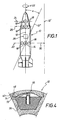
Figur 1 eine schematische Seitenansicht des bahnkorrigierbaren Projektils,- Figur 2 einen Segmentausschnitt einer ersten Ausführungsform des Projektils gemäß
Figur 1, - Figur 3 eine der Figur 2 entsprechende Querschnittsdarstellung durch eine zweite Ausführungsform des Projektils, und
- Figur 4 eine den Figuren 2 und 3 entsprechende Schnittdarstellung durch eine dritte Ausführungsform des Projektils.
- FIG. 1 shows a schematic side view of the projectile that can be corrected for a path,
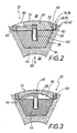
- FIG. 2 shows a segment section of a first embodiment of the projectile according to FIG. 1,
- 3 shows a cross-sectional representation corresponding to FIG. 2 through a second embodiment of the projectile, and
- Figure 4 is a sectional view corresponding to Figures 2 and 3 through a third embodiment of the projectile.
Die Figur 1 zeigt ein Projektil 10 mit zentraler Längsachse 12 und Schwerpunkt 14. Es weist eine Anzahl an seinem Umfang verteilt angeordneter Querschub-Antriebseinrichtungen 16 auf. Diese sind in einer zur zentralen Längsachse 12 senkrecht ausgerichteten Ebene angeordnet, die durch den Schwerpunkt 14 verläuft. Weitere Querschub-Antriebeinrichtungen 18 sind in Ebenen 24, 26 angeordnet, die auch zur zentralen Längsachse 12 senkrecht orientiert sind, die aber vom Schwerpunkt 14 einen Abstand besitzen. Wird mittels einer als Block angedeuteten Steuereinrichtung 28 abhängig vom Drall 22 eine der Antriebseinrichtungen 16 aktiviert, so ergibt sich infolge Rückstoßwirkung ein annähernd paralleler Versatz 30 der Bahn des Projektils 10 in eine Längsachse 12′. Wird dagegen mit Hilfe der Steuereinrichtung 28 eine der Antriebseinrichtungen 18 aktiviert, so wird die Längsachse 12 bspw. um den Winkel a in Richtung der Längsachse 12˝ verschwenkt. Durch geeignete Aktivierung der einen oder anderen der Antriebseinrichtungen 16, 18 ist es demnach möglich, die Flugbahn des Projektils 10 zu steuern.FIG. 1 shows a
Figur 2 zeigt einen Teilschnitt durch das Projektil 10 in Form eines Kreisringsegmentes, aus dem eine Ausbildung einer Antriebseinrichtung 16 bzw. 18 ersichtlich ist. Das Projektil 10 weist einen zentralen Hohlraum 32 zur Aufnahme einer Nutzlast auf, bspw. einer Wirkladung einschließlich Sicherungs- und Zündeinrichtungen. In der Wandung 34 des Projektils 10 sind entlang seines Umfanges Ausnehmungen 36 in radialer Richtung vom zentralen Hohlraum 32 des Projektils 10 zu seiner Außenseite 38 hin erweitert ausgebildet. Jede Ausnehmung ist an ihrem außenseitigen Endabschnitt an einer zylindrischen Einsenkung 40 mit einem Innengewindeabschnitt 42 versehen. In der Ausnehmung 36 ist eine Impulsladung 44 angeordnet. Jede Ausnehmung 36 ist mittels eines zugehörigen Deckels 46 verschlossen, der hier gegen die Impulsladung 44 gepreßt ist, und der einen kreisrunden Umfangsrand 48 mit einem dem Innengewindeabschnitt 42 entsprechenden Außengewindeabschnitt 50 aufweist. In einem Abstand vom Umfangsrand 48 verläuft um den Deckel 46 eine Sollbruchstelle 52 vorbestimmter Abreißfestigkeit. Dafür sind an der Außenseite 54 und an der Innenseite 58 des Deckels 46 umlaufende Rillen 56, 60 vorgesehen.FIG. 2 shows a partial section through the
In die Impulsladung 44 ragt radial von außen ein Detonator 62 mit elektrischem Anschlußkabel 64, das mit einer (in Figur 1 als Block angedeuteten) Steuereinrichtung 28 wirkverbunden ist. An der Außenseite 54 des Deckels 46 ist ein Montagefenster 66 für das Anschlußkabel 61. Aus Figur 2 ist auch ersichtlich, daß die Außenseite 54 des Deckels 46 eine an die Außenkontur des Projektils 10 angepaßte Kontur aufweist.A
Wird der Detonator 62 über die Steuereinrichtung 28 (s. Figur 1) elektrisch aktiviert, so wird die entsprechende Impulsladung 44 gezündet. Hierdurch baut sich in der durch den Deckel 46 abgeschlossenen Ausnehmung 36 ein derartig hoher Druck auf, daß schließlich der Deckel 46 entlang des Sollbruchabschnittes 52 abreißt und vom Projektil 10 radialweggeschleudert wird. Daraus resultiert nach dem Impulserhaltungssatz eine Bewegung des Projektils 10 in Richtung des Pfeiles 68.If the
Figur 3 zeigt eine Ausbildung des Projektils 10, die sich von der in Figur 2, insbes. dadurch unterscheidet, daß die Innenseite 58 des Deckels 46 nicht direkt an der Impulsladung 44 anliegt, sondern konkav eingewölbt ist, so daß sich zwischen der Impulsladung 44 und der Innenseite 58 des Deckels 46 ein druckaufnehmender Zwischenraum 70 ergibt. Dadurch kann nun das Anschlußkabel 64 - entgegen Figur 2 - statt durch den Deckel 46 hindurch unterhalb des Deckels 46 angeordnet sein. Außerdem ist bei dieser Ausbildung der Deckel 46 nur innenseitig mit einer umlaufenden Rille 60 versehen, während seine Außenseite 54 glatt ist.Figure 3 shows an embodiment of the
Figur 4 zeigt eine dritte Ausbildung des Projektils 10 in einem Teilabschnitt entsprechend den Figuren 2 und 3, wobei für eine formschlüssige Sollbruchstelle der Deckel 46 mit einem umlaufenden Befestigungswulst 72 und die zylindrische Einsenkung 40 der Ausnehmung 36 mit einer eine Hinterschneidung bildenden Rille 74 ausgebildet ist. Dadurch ist es nicht mehr erforderlich, die zylindrische Einsenkung 40 mit einem Innengewindeabschnitt und den Umfangsrand 48 des Deckels 46 mit einem Außengewindeabschnitt auszubilden, was eine Produktions-Vereinfachung bedeutet. Der in die Rille 74 eingepreßte umlaufende Befestigungswulst 72 des Deckels 46 bildet also nun einen Verbindungsabschnitt vorbestimmter Abreißfestigkeit.FIG. 4 shows a third embodiment of the
Claims (7)
dadurch gekennzeichnet,
daß der Detonator (62) bei zunächst koaxial mit dem Deckel (46) und dann dagegen abgewinkelt verlaufendem Anschlußkabel (64) im Übergangsbereich zwischen der Impulsladung (44) und dem Deckel (46) angeordnet ist, wobei der Deckel (46) unter Anpassung seiner Außenkontur an die Kontur der umgebenden Projektil-Mantelfläche über eine Sollbruchstelle (52) an der Struktur des Projektils (10) festgelegt ist, die radial innerhalb der Impulsladung (44) hermetisch zum Projektil-Zentrum verschlossen ist.1. Path-correctable spin-stabilized projectile (10) with transverse thrust drive devices (16; 18) distributed over its circumference, each with a pulse charge (44) arranged radially with respect to the longitudinal axis of the projectile (12) and including an electrically controllable detonator (62 ),
characterized,
that the detonator (62) is arranged in the transition region between the pulse charge (44) and the cover (46), initially with the cover (46) and then angled in relation to it angled connecting cable (64), the cover (46) adapting it The outer contour is fixed to the contour of the surrounding projectile jacket surface via a predetermined breaking point (52) on the structure of the projectile (10), which is hermetically sealed radially within the impulse charge (44) to the projectile center.
dadurch gekennzeichnet, daß unter einem konkav eingewölbten und mit einem Randbereich gegen die Impulsladung (44) radial anliegenden Deckel (46) ein Hohlraum ausgespart ist, durch den das Anschlußkabel (64) zur elektrischen Ansteuerung des Detonators (62) unter den Rand des Deckels (46) abtauchend verläuft.2. projectile according to claim 1,
characterized in that a cavity is cut out under a concavely arched cover (46) which lies radially with an edge region against the impulse charge (44) and through which the connecting cable (64) for the electrical control of the detonator (62) under the edge of the cover ( 46) descending.
dadurch gekennzeichnet,
daß die Innenseite des Deckels (46) im wesentlichen vollflächig gegen die Impulsladung (44) den Detonator (62) anliegt, mit Verlauf des Anschlußkabels (64) für die elektrische Ansteuerung des Detonators (62) durch einen radial bezüglich der Deckel-Achse verlaufenden Kanal.3. projectile according to claim 1,
characterized,
that the inside of the cover (46) rests essentially over the entire area against the pulse charge (44) the detonator (62), with the connection cable (64) running for the electrical control of the detonator (62) through a channel running radially with respect to the cover axis .
dadurch gekennzeichnet,
daß die Sollbruchstelle (52) eines jeden Deckels (46) innerhalb eines längs des Deckel-Randes (48) umlaufenden Außengewindes (50) für dessen formschlüssige Festlegung in einer Ausnehmung (36) zur Aufnahme der Impulsladung (44) ausgebildet ist.4. Projectile according to one of the preceding claims,
characterized,
that the predetermined breaking point (52) of each cover (46) is formed within an external thread (50) running along the edge of the cover (48) for positive locking in a recess (36) for receiving the impulse charge (44).
dadurch gekennzeichnet,
daß eine einteilige Sollbruchstelle (52) mit mechanisch geschwächtem Bereich vorgesehen ist.5. projectile according to claim 4,
characterized,
that a one-piece predetermined breaking point (52) with a mechanically weakened area is provided.
dadurch gekennzeichnet,
daß eine formschlüssig-mehrteilige Sollbruchstelle (52) mit in eine Rille (74) umlaufend eingreifendem Befestigungswulst (72) vorgesehen ist.6. projectile according to claim 4,
characterized,
that a form-fitting, multi-part predetermined breaking point (52) is provided with a fastening bead (72) which engages in a groove (74) all around.
dadurch gekennzeichnet,
daß Querschub-Antriebseinrichtungen (16; 18) längs des Projektil-Umfanges in verschiedenenen Projektil-Querschnittsebenen angeordnet sind, von denen eine Ebene (20) durch den Projektil-Schwerpunkt (14) verläuft, während wenigstens eine weitere Ebene (24, 26) weit aus dem Schwerpunkt (14) heraus in den Bereich des konischen Projektil-Frontabschnittes verlegt ist.7. projectile according to one of the preceding claims,
characterized,
that transverse thrust drive devices (16; 18) are arranged along the projectile circumference in different projectile cross-sectional planes, of which one plane (20) runs through the projectile center of gravity (14), while at least one further plane (24, 26) is wide from the center of gravity (14) in the area of the conical projectile front section.
Applications Claiming Priority (2)
| Application Number | Priority Date | Filing Date | Title |
|---|---|---|---|
| DE3931173 | 1989-09-19 | ||
| DE3931173 | 1989-09-19 |
Publications (3)
| Publication Number | Publication Date |
|---|---|
| EP0418636A2 true EP0418636A2 (en) | 1991-03-27 |
| EP0418636A3 EP0418636A3 (en) | 1991-04-17 |
| EP0418636B1 EP0418636B1 (en) | 1993-12-29 |
Family
ID=6389691
Family Applications (1)
| Application Number | Title | Priority Date | Filing Date |
|---|---|---|---|
| EP90116937A Expired - Lifetime EP0418636B1 (en) | 1989-09-19 | 1990-09-04 | Projectile with trajectory control system |
Country Status (3)
| Country | Link |
|---|---|
| US (1) | US5054712A (en) |
| EP (1) | EP0418636B1 (en) |
| DE (1) | DE59004020D1 (en) |
Cited By (10)
| Publication number | Priority date | Publication date | Assignee | Title |
|---|---|---|---|---|
| EP0485897A1 (en) * | 1990-11-14 | 1992-05-20 | DIEHL GMBH & CO. | Projectile with trajectory correction |
| DE4408085A1 (en) * | 1994-03-10 | 1995-09-14 | Rheinmetall Ind Gmbh | Missile guidance device |
| DE10141169A1 (en) * | 2001-08-22 | 2003-03-13 | Diehl Munitionssysteme Gmbh | artillery rocket |
| EP2071270A2 (en) | 2007-12-10 | 2009-06-17 | Diehl BGT Defence GmbH & Co.KG | Tilted igniter |
| WO2013130518A1 (en) * | 2012-03-02 | 2013-09-06 | Alliant Techsystems Inc. | Methods and apparatuses for active protection from aerial threats |
| DE102014014952A1 (en) * | 2014-10-08 | 2016-04-14 | Mbda Deutschland Gmbh | missile |
| DE102014014950A1 (en) * | 2014-10-08 | 2016-04-28 | Mbda Deutschland Gmbh | missile |
| US9501055B2 (en) | 2012-03-02 | 2016-11-22 | Orbital Atk, Inc. | Methods and apparatuses for engagement management of aerial threats |
| US9551552B2 (en) | 2012-03-02 | 2017-01-24 | Orbital Atk, Inc. | Methods and apparatuses for aerial interception of aerial threats |
| US11947349B2 (en) | 2012-03-02 | 2024-04-02 | Northrop Grumman Systems Corporation | Methods and apparatuses for engagement management of aerial threats |
Families Citing this family (29)
| Publication number | Priority date | Publication date | Assignee | Title |
|---|---|---|---|---|
| DE4410326C2 (en) * | 1994-03-25 | 1998-07-02 | Rheinmetall Ind Ag | Projectile with a device for trajectory correction |
| US5669581A (en) * | 1994-04-11 | 1997-09-23 | Aerojet-General Corporation | Spin-stabilized guided projectile |
| US6254031B1 (en) * | 1994-08-24 | 2001-07-03 | Lockhead Martin Corporation | Precision guidance system for aircraft launched bombs |
| US5647558A (en) * | 1995-02-14 | 1997-07-15 | Bofors Ab | Method and apparatus for radial thrust trajectory correction of a ballistic projectile |
| DE19540378C1 (en) * | 1995-10-30 | 1997-01-23 | Daimler Benz Aerospace Ag | Release device for rocket pipes, especially for aggressive propellants |
| AU5957898A (en) * | 1997-01-02 | 1998-08-07 | Tibor G. Horwath | Reticle for use in a guidance seeker for a spinning projectile |
| US6722609B2 (en) | 1998-02-13 | 2004-04-20 | James M. Linick | Impulse motor and apparatus to improve trajectory correctable munitions including cannon launched munitions, glide bombs, missiles, rockets and the like |
| US6308911B1 (en) * | 1998-10-30 | 2001-10-30 | Lockheed Martin Corp. | Method and apparatus for rapidly turning a vehicle in a fluid medium |
| FR2795135B1 (en) * | 1999-06-16 | 2001-08-31 | Centre Nat Etd Spatiales | POWDER MICROPROPULSION SYSTEM AND METHOD FOR PRODUCING SUCH A MICROPROPULSION SYSTEM |
| US6695251B2 (en) * | 2001-06-19 | 2004-02-24 | Space Systems/Loral, Inc | Method and system for synchronized forward and Aft thrust vector control |
| US6752351B2 (en) * | 2002-11-04 | 2004-06-22 | The United States Of America As Represented By The Secretary Of The Navy | Low mass flow reaction jet |
| US7795567B2 (en) * | 2005-04-05 | 2010-09-14 | Raytheon Company | Guided kinetic penetrator |
| US7416154B2 (en) * | 2005-09-16 | 2008-08-26 | The United States Of America As Represented By The Secretary Of The Army | Trajectory correction kit |
| DE102005052474B3 (en) * | 2005-11-03 | 2007-07-12 | Junghans Feinwerktechnik Gmbh & Co. Kg | Spiked artillery projectile |
| US7851732B2 (en) * | 2006-03-07 | 2010-12-14 | Raytheon Company | System and method for attitude control of a flight vehicle using pitch-over thrusters |
| IL178840A0 (en) * | 2006-10-24 | 2007-09-20 | Rafael Advanced Defense Sys | System |
| US7872215B2 (en) * | 2008-02-29 | 2011-01-18 | Raytheon Company | Methods and apparatus for guiding a projectile |
| US8618455B2 (en) * | 2009-06-05 | 2013-12-31 | Safariland, Llc | Adjustable range munition |
| WO2011088277A1 (en) | 2010-01-15 | 2011-07-21 | Lockheed Martin Corporation | Monolithic attitude control motor frame and system |
| US8735788B2 (en) * | 2011-02-18 | 2014-05-27 | Raytheon Company | Propulsion and maneuvering system with axial thrusters and method for axial divert attitude and control |
| US11313650B2 (en) | 2012-03-02 | 2022-04-26 | Northrop Grumman Systems Corporation | Methods and apparatuses for aerial interception of aerial threats |
| US9018572B2 (en) * | 2012-11-06 | 2015-04-28 | Raytheon Company | Rocket propelled payload with divert control system within nose cone |
| US20140137539A1 (en) * | 2012-11-19 | 2014-05-22 | Raytheon Company | Thrust-producing device with detonation motor |
| US9068808B2 (en) * | 2013-01-17 | 2015-06-30 | Raytheon Company | Air vehicle with bilateral steering thrusters |
| US9377279B2 (en) * | 2014-04-22 | 2016-06-28 | Raytheon Company | Rocket cluster divert and attitude control system |
| US10914559B1 (en) * | 2016-11-21 | 2021-02-09 | Lockheed Martin Corporation | Missile, slot thrust attitude controller system, and method |
| RU2687827C1 (en) * | 2018-11-23 | 2019-05-16 | Акционерное общество "Научно-производственное предприятие "Дельта" | Method for increasing firing range by means of corrected artillery ammunition |
| RU2702035C1 (en) * | 2019-03-21 | 2019-10-03 | Акционерное общество "Научно-производственное предприятие "Дельта" | Method of correction of ellipse of scattering of artillery rotating projectiles |
| RU2767645C1 (en) * | 2020-10-19 | 2022-03-18 | Российская Федерация, от имени которой выступает Министерство обороны Российской Федерации | Anti-aircraft guided missile 9m96 |
Citations (5)
| Publication number | Priority date | Publication date | Assignee | Title |
|---|---|---|---|---|
| US3028807A (en) * | 1959-08-24 | 1962-04-10 | Mcdonnell Aircraft Corp | Guidance system |
| US3034434A (en) * | 1960-03-08 | 1962-05-15 | Frank H Swaim | Thrust vector control system |
| GB1008595A (en) * | 1963-07-08 | 1965-10-27 | Fike Metal Prod Corp | A rupture plate adapted to control the flow of fluid from a container |
| FR2232721A1 (en) * | 1973-06-08 | 1975-01-03 | Barker Geoffrey | |
| US3964390A (en) * | 1971-03-31 | 1976-06-22 | Imperial Chemical Industries Limited | Bursting disc assembly |
Family Cites Families (9)
| Publication number | Priority date | Publication date | Assignee | Title |
|---|---|---|---|---|
| SE331435B (en) * | 1969-04-23 | 1970-12-21 | Bofors Ab | |
| CA1009370A (en) * | 1972-01-03 | 1977-04-26 | Ship Systems | Laser guided projectile |
| SE429064B (en) * | 1976-04-02 | 1983-08-08 | Bofors Ab | FINAL PHASE CORRECTION OF ROTATING PROJECTILE |
| FR2386802A1 (en) * | 1977-04-08 | 1978-11-03 | Thomson Brandt | CONTROL DEVICE FOR PROJECTILE OF THE MISSILE GENUS, AND PROJECTILE EQUIPPED WITH THIS DEVICE |
| FR2469345A1 (en) * | 1979-11-09 | 1981-05-22 | Thomson Brandt | METHOD FOR DRIVING AND GUIDING TERMINAL PROJECTILES AND PROJECTILES INCLUDING MEANS FOR CARRYING OUT SAID METHOD |
| FR2504703B1 (en) * | 1981-04-24 | 1986-09-05 | Stauff Emile | SYSTEM FOR CONTROLLING A PROJECTILE TO AN AXIAL REFERENCE TO ELIMINATE THE WIND EFFECT |
| US4503773A (en) * | 1982-12-27 | 1985-03-12 | Thiokol Corporation | Aft end igniter for full, head-end web solid propellant rocket motors |
| DE3521204A1 (en) * | 1985-06-13 | 1986-12-18 | Diehl GmbH & Co, 8500 Nürnberg | IMPULSE ENGINE |
| GB8822282D0 (en) * | 1988-09-22 | 1989-04-19 | British Aerospace | Course correction unit |
-
1990
- 1990-09-04 EP EP90116937A patent/EP0418636B1/en not_active Expired - Lifetime
- 1990-09-04 DE DE90116937T patent/DE59004020D1/en not_active Expired - Fee Related
- 1990-09-10 US US07/580,333 patent/US5054712A/en not_active Expired - Fee Related
Patent Citations (5)
| Publication number | Priority date | Publication date | Assignee | Title |
|---|---|---|---|---|
| US3028807A (en) * | 1959-08-24 | 1962-04-10 | Mcdonnell Aircraft Corp | Guidance system |
| US3034434A (en) * | 1960-03-08 | 1962-05-15 | Frank H Swaim | Thrust vector control system |
| GB1008595A (en) * | 1963-07-08 | 1965-10-27 | Fike Metal Prod Corp | A rupture plate adapted to control the flow of fluid from a container |
| US3964390A (en) * | 1971-03-31 | 1976-06-22 | Imperial Chemical Industries Limited | Bursting disc assembly |
| FR2232721A1 (en) * | 1973-06-08 | 1975-01-03 | Barker Geoffrey |
Cited By (20)
| Publication number | Priority date | Publication date | Assignee | Title |
|---|---|---|---|---|
| EP0485897A1 (en) * | 1990-11-14 | 1992-05-20 | DIEHL GMBH & CO. | Projectile with trajectory correction |
| DE4408085A1 (en) * | 1994-03-10 | 1995-09-14 | Rheinmetall Ind Gmbh | Missile guidance device |
| DE4408085C2 (en) * | 1994-03-10 | 1999-08-12 | Rheinmetall W & M Gmbh | Device for guiding a missile not rotating about its longitudinal axis |
| DE10141169A1 (en) * | 2001-08-22 | 2003-03-13 | Diehl Munitionssysteme Gmbh | artillery rocket |
| EP1286128B2 (en) † | 2001-08-22 | 2009-07-29 | Diehl BGT Defence GmbH & Co.KG | Satellite controlloed artillery rocket with side thrust corrector |
| EP2071270A2 (en) | 2007-12-10 | 2009-06-17 | Diehl BGT Defence GmbH & Co.KG | Tilted igniter |
| EP2071270A3 (en) * | 2007-12-10 | 2012-12-05 | Diehl BGT Defence GmbH & Co.KG | Tilted igniter |
| US10295312B2 (en) | 2012-03-02 | 2019-05-21 | Northrop Grumman Innovation Systems, Inc. | Methods and apparatuses for active protection from aerial threats |
| US9170070B2 (en) | 2012-03-02 | 2015-10-27 | Orbital Atk, Inc. | Methods and apparatuses for active protection from aerial threats |
| US9501055B2 (en) | 2012-03-02 | 2016-11-22 | Orbital Atk, Inc. | Methods and apparatuses for engagement management of aerial threats |
| US9551552B2 (en) | 2012-03-02 | 2017-01-24 | Orbital Atk, Inc. | Methods and apparatuses for aerial interception of aerial threats |
| US10228689B2 (en) | 2012-03-02 | 2019-03-12 | Northrop Grumman Innovation Systems, Inc. | Methods and apparatuses for engagement management of aerial threats |
| WO2013130518A1 (en) * | 2012-03-02 | 2013-09-06 | Alliant Techsystems Inc. | Methods and apparatuses for active protection from aerial threats |
| US10436554B2 (en) | 2012-03-02 | 2019-10-08 | Northrop Grumman Innovation Systems, Inc. | Methods and apparatuses for aerial interception of aerial threats |
| US10948909B2 (en) | 2012-03-02 | 2021-03-16 | Northrop Grumman Innovation Systems, Inc. | Methods and apparatuses for engagement management of aerial threats |
| US10982935B2 (en) | 2012-03-02 | 2021-04-20 | Northrop Grumman Systems Corporation | Methods and apparatuses for active protection from aerial threats |
| US11947349B2 (en) | 2012-03-02 | 2024-04-02 | Northrop Grumman Systems Corporation | Methods and apparatuses for engagement management of aerial threats |
| DE102014014952A1 (en) * | 2014-10-08 | 2016-04-14 | Mbda Deutschland Gmbh | missile |
| DE102014014950A1 (en) * | 2014-10-08 | 2016-04-28 | Mbda Deutschland Gmbh | missile |
| DE102014014952B4 (en) * | 2014-10-08 | 2016-05-25 | Mbda Deutschland Gmbh | missile |
Also Published As
| Publication number | Publication date |
|---|---|
| DE59004020D1 (en) | 1994-02-10 |
| EP0418636B1 (en) | 1993-12-29 |
| US5054712A (en) | 1991-10-08 |
| EP0418636A3 (en) | 1991-04-17 |
Similar Documents
| Publication | Publication Date | Title |
|---|---|---|
| EP0418636A2 (en) | Projectile with trajectory control system | |
| DE102005030090B4 (en) | Throw-off hood and missile with detachable hood | |
| EP0806623A1 (en) | Spin stabilised carrier projectile | |
| DE102006048299B3 (en) | Cylindrical active charge | |
| EP1002213A1 (en) | System for protecting objects against shaped charges | |
| DE4123649C2 (en) | Ejection device | |
| EP0162250B1 (en) | Missile with a remotely operating warhead | |
| EP0062750A1 (en) | Method for the dispersal of subcharges from a carrier missile | |
| EP0433940B1 (en) | Emergency exit device for an armoured vehicle | |
| DE3415625C2 (en) | ||
| DE2519507A1 (en) | Warhead for attacking aerial targets - with target seeking guidance system and transverse hollow charges aligned on the target | |
| DE3843804C2 (en) | ||
| DE4337444B4 (en) | Improvements in or related to solid fuel burners | |
| EP0435083B1 (en) | Adjustable stand-off member on a warhead with a hollow charge switchable between penetration and side operation | |
| DE3501649C2 (en) | ||
| DE2608961C3 (en) | Centrifugal device | |
| DE2829002A1 (en) | Multiple headed missile system - moves initial- and after-action bodies apart axially before detonation | |
| EP0485897B1 (en) | Projectile with trajectory correction | |
| EP3210653B1 (en) | Stationary fire extinguishing device | |
| EP0341543A1 (en) | Shotgun slug cartridge | |
| DE102017112601B4 (en) | Separating device for separating electrical conductors, system with separation device and method for separating electrical conductors | |
| DE3116930C2 (en) | Device for initiating an explosive charge | |
| DE60102493T2 (en) | Self-refracting assembly of a vehicle battery | |
| EP1682848B1 (en) | Structure of a projectile | |
| DE60008844T2 (en) | Pyrotechnic safety device for a motor vehicle |
Legal Events
| Date | Code | Title | Description |
|---|---|---|---|
| PUAI | Public reference made under article 153(3) epc to a published international application that has entered the european phase |
Free format text: ORIGINAL CODE: 0009012 |
|
| PUAL | Search report despatched |
Free format text: ORIGINAL CODE: 0009013 |
|
| AK | Designated contracting states |
Kind code of ref document: A2 Designated state(s): DE FR GB IT NL |
|
| AK | Designated contracting states |
Kind code of ref document: A3 Designated state(s): DE FR GB IT NL |
|
| 17P | Request for examination filed |
Effective date: 19910314 |
|
| 17Q | First examination report despatched |
Effective date: 19920902 |
|
| RAP1 | Party data changed (applicant data changed or rights of an application transferred) |
Owner name: DEUTSCH-FRANZOESISCHES FORSCHUNGSINSTITUT SAINT-L Owner name: DIEHL GMBH & CO. |
|
| RIN1 | Information on inventor provided before grant (corrected) |
Inventor name: LEHR, HARMUTH Inventor name: SCHIRM, VOLKER Inventor name: WIESE, ULRICH Inventor name: LEHRIEDER, GUENTHER Inventor name: BAER, KLAUS |
|
| RIN1 | Information on inventor provided before grant (corrected) |
Inventor name: LEHR, HARTMUTH Inventor name: SCHIRM, VOLKER Inventor name: WIESE, ULRICH Inventor name: LEHRIEDER, GUENTHER Inventor name: BAER, KLAUS |
|
| GRAA | (expected) grant |
Free format text: ORIGINAL CODE: 0009210 |
|
| AK | Designated contracting states |
Kind code of ref document: B1 Designated state(s): DE FR GB IT NL |
|
| REF | Corresponds to: |
Ref document number: 59004020 Country of ref document: DE Date of ref document: 19940210 |
|
| ITF | It: translation for a ep patent filed |
Owner name: STUDIO JAUMANN |
|
| GBT | Gb: translation of ep patent filed (gb section 77(6)(a)/1977) |
Effective date: 19940331 |
|
| ET | Fr: translation filed | ||
| PG25 | Lapsed in a contracting state [announced via postgrant information from national office to epo] |
Ref country code: GB Effective date: 19940904 |
|
| PLBE | No opposition filed within time limit |
Free format text: ORIGINAL CODE: 0009261 |
|
| STAA | Information on the status of an ep patent application or granted ep patent |
Free format text: STATUS: NO OPPOSITION FILED WITHIN TIME LIMIT |
|
| 26N | No opposition filed | ||
| PG25 | Lapsed in a contracting state [announced via postgrant information from national office to epo] |
Ref country code: NL Effective date: 19950401 |
|
| GBPC | Gb: european patent ceased through non-payment of renewal fee |
Effective date: 19940904 |
|
| NLV4 | Nl: lapsed or anulled due to non-payment of the annual fee | ||
| PGFP | Annual fee paid to national office [announced via postgrant information from national office to epo] |
Ref country code: DE Payment date: 20001122 Year of fee payment: 11 |
|
| PG25 | Lapsed in a contracting state [announced via postgrant information from national office to epo] |
Ref country code: DE Free format text: LAPSE BECAUSE OF NON-PAYMENT OF DUE FEES Effective date: 20020601 |
|
| PGFP | Annual fee paid to national office [announced via postgrant information from national office to epo] |
Ref country code: FR Payment date: 20020828 Year of fee payment: 13 |
|
| PG25 | Lapsed in a contracting state [announced via postgrant information from national office to epo] |
Ref country code: FR Free format text: LAPSE BECAUSE OF NON-PAYMENT OF DUE FEES Effective date: 20040528 |
|
| REG | Reference to a national code |
Ref country code: FR Ref legal event code: ST |
|
| PG25 | Lapsed in a contracting state [announced via postgrant information from national office to epo] |
Ref country code: IT Free format text: LAPSE BECAUSE OF NON-PAYMENT OF DUE FEES;WARNING: LAPSES OF ITALIAN PATENTS WITH EFFECTIVE DATE BEFORE 2007 MAY HAVE OCCURRED AT ANY TIME BEFORE 2007. THE CORRECT EFFECTIVE DATE MAY BE DIFFERENT FROM THE ONE RECORDED. Effective date: 20050904 |