EP0415325A2 - Appareil de traitement de signal vidéo - Google Patents
Appareil de traitement de signal vidéo Download PDFInfo
- Publication number
- EP0415325A2 EP0415325A2 EP90116396A EP90116396A EP0415325A2 EP 0415325 A2 EP0415325 A2 EP 0415325A2 EP 90116396 A EP90116396 A EP 90116396A EP 90116396 A EP90116396 A EP 90116396A EP 0415325 A2 EP0415325 A2 EP 0415325A2
- Authority
- EP
- European Patent Office
- Prior art keywords
- video signal
- signal
- motion
- detecting
- coefficient
- Prior art date
- Legal status (The legal status is an assumption and is not a legal conclusion. Google has not performed a legal analysis and makes no representation as to the accuracy of the status listed.)
- Granted
Links
Images


Classifications
-
- H—ELECTRICITY
- H04—ELECTRIC COMMUNICATION TECHNIQUE
- H04N—PICTORIAL COMMUNICATION, e.g. TELEVISION
- H04N7/00—Television systems
- H04N7/01—Conversion of standards, e.g. involving analogue television standards or digital television standards processed at pixel level
-
- H—ELECTRICITY
- H04—ELECTRIC COMMUNICATION TECHNIQUE
- H04N—PICTORIAL COMMUNICATION, e.g. TELEVISION
- H04N5/00—Details of television systems
- H04N5/14—Picture signal circuitry for video frequency region
- H04N5/144—Movement detection
-
- H—ELECTRICITY
- H04—ELECTRIC COMMUNICATION TECHNIQUE
- H04N—PICTORIAL COMMUNICATION, e.g. TELEVISION
- H04N7/00—Television systems
- H04N7/01—Conversion of standards, e.g. involving analogue television standards or digital television standards processed at pixel level
- H04N7/0117—Conversion of standards, e.g. involving analogue television standards or digital television standards processed at pixel level involving conversion of the spatial resolution of the incoming video signal
- H04N7/012—Conversion between an interlaced and a progressive signal
Definitions
- This invention relates to a video signal processing apparatus including an interpolator controlled by a motion detector.
- a prior-art video signal processing apparatus includes an inter-line interpolator, an inter-field interpolator, and a motion detector which detects a motion of an object on the basis of a signal representative of a luminance difference between frames of a video signal. In the presence of a detection output from the motion detector, an interpolation signal generated by the inter-line interpolator is selected. In the absence of a detection output from the motion detector, an interpolation signal generated by the inter-field interpolator is selected or a weighted addition of the interpolation signals generated by the two interpolators is used.
- a certain condition such as a slight vibration of an object in a vertical direction or a sudden disappearance of a horizontally-extending edge of a superimposed letter tend to be detected as a motion which causes a change of the interpolation from the inter-field type to the inter-line type. It is generally better to maintain the inter-field interpolation under such a certain condition from the standpoint of the quality of a reproduced image.
- a video signal processing apparatus comprises means for detecting a correlation between frames represented by a video signal of an interlaced scanning format; means for detecting a sudden motion of an object represented by the video signal on the basis of said detected correlation; means for detecting a normal motion of the object represented by the video signal on the basis of said detected correlation; means for interpolating scanning lines represented by the video signal with changeable interpolation characteristics; means for changing the interpolation characteristics in response to said detected normal motion of the object; and means for changing the interpolation characteristics in response to said detected sudden motion of the object.
- a video signal processing apparatus comprises difference detecting means for detecting a difference between frames represented by a video signal of an interlaced scanning format, and for generating a frame difference signal representative of said detected difference between the frames; means for generating a motion coefficient on the basis of said frame difference signal; means for interpolating scanning lines represented by said video signal with changeable interpolation characteristics; means for changing said interpolation characteristics in accordance with said motion coefficient; means for comparing said frame difference signal with a signal representative of a predetermined threshold; means for taking out results of said comparing at adjacent pixels; pattern detecting means for detecting that said taken-out results have a predetermined pattern; and means for changing said motion coefficient to change the interpolation characteristics toward interpolation characteristics suited to a stationary picture when said pattern detecting means detects that the taken-out results have the predetermined pattern.
- a video signal processing apparatus comprises difference detecting means for detecting a difference between frames represented by a video signal of an interlaced scanning format, and for generating a frame difference signal representative of said detected difference between the frames; means for generating a motion coefficient on the basis of said frame difference signal; means for interpolating scanning lines represented by said video signal with changeable interpolation characteristics; means for changing said interpolation characteristics in accordance with said motion coefficient; means for comparing said frame difference signal with a signal representative of a predetermined threshold; means for taking out results of said comparing at adjacent pixels; pattern detecting means for detecting that said taken-out results have a predetermined pattern, and for outputting a signal representative of a result of the detection that said taken-out results have the predetermined pattern; outline detecting means for detecting a horizontal outline of an object represented by the video signal, and for outputting a signal representative of said detected horizontal outline; means for gating the output signal from said pattern detecting means in response to the output signal from said outline detecting means;
- a video signal processing apparatus comprises difference detecting means for detecting a difference between frames represented by a video signal of an interlaced scanning format, and for generating a frame difference signal representative of said detected difference between the frames; means for generating a motion coefficient on the basis of said frame difference signal; means for interpolating scanning lines represented by said video signal with changeable interpolation characteristics; means for changing said interpolation characteristics in accordance with said motion coefficient; outline detecting means for detecting a horizontal outline of an object represented by the video signal, and for outputting a signal representative of said detected horizontal outline; means for setting a threshold signal representative of a threshold in accordance with the output signal from said outline detecting means; means for comparing said frame difference signal with said threshold signal; means for taking out results of said comparing at adjacent pixels; pattern detecting means for detecting that said taken-out results have a predetermined pattern, and for outputting a signal representative of a result of the detection that said taken-out results have the predetermined pattern; and means for changing said motion coefficient in
- a video signal processing apparatus comprises means for interpolating parts of a video signal with changeable interpolation characteristics; means for detecting a predetermined sudden vertical motion of an object represented by the video signal; and means for changing said interpolation characteristics when said detecting means detects the sudden vertical motion.
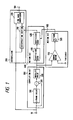
- a video signal processing apparatus includes a scanning line interpolator 200 and an inter-frame correlation detector 300.
- a video signal of an interlaced scanning format is applied to the scanning line interpolator 200 and the inter-frame correlation detector 300 via an input terminal 10.
- the inter-frame correlation detector 300 includes a 1-frame period delay device 310, a subtracter 320, and an absolute value circuit 330.
- the video signal is applied to the 1-frame period delay device 310 and a first input terminal of the subtracter 320.
- the video signal is delayed by the 1-frame period delay device 310 by a 1-frame period.
- the output signal from the 1-frame period delay device 310 that is, the delayed video signal, is applied to a second input terminal of the subtracter 320.
- the subtracter 320 derives a difference between the non-delayed video signal and the delayed video signal, and outputs a signal representing a difference between two successive frames of the video signal.
- the frame difference signal is fed from the subtracter 320 to the absolute value circuit 330.
- the frame difference signal is converted by the absolute value circuit 330 into an absolute frame difference signal representing the absolute value of the frame difference signal.
- the absolute frame difference signal is outputted from the absolute value circuit 330 to a normal motion detector 400 and a sudden motion detector 500.
- the normal motion detector 400 includes a coefficient generator 410 and a coefficient converter 420.
- the absolute frame difference signal is fed to the coefficient generator 410.
- the coefficient generator 410 generates a signal representative of a primary motion coefficient k1 in dependence upon the absolute frame difference signal.
- the primary motion coefficient k1 is set to "1" when the absolute value of the difference between the two successive frames exceeds a predetermined threshold, that is, when an appreciable motion of an object is present, and the primary motion coefficient k1 is set to "0" in other cases.
- the primary motion coefficient k1 equals "1" when an image is appreciably moving
- the primary motion coefficient k1 equals "0" when an image is substantially stationary.
- the primary motion coefficient k1 may be varied continuously between “0" and "1" as the absolute value of the difference between the two successive frames increases from its minimum to its maximum.
- the primary motion coefficient signal is outputted from the coefficient generator 410 to the coefficient converter 420.
- the coefficient converter 420 changes the primary motion coefficient signal into a signal representative of a final motion coefficient k2 in response to a detection signal outputted from the sudden motion detector 500.
- the coefficient converter 420 converts the primary motion coefficient k1 into the final motion coefficient k2 in response to the detection signal from the sudden motion detector 500.
- the final motion coefficient signal is outputted from the coefficient converter 420 to the scanning line interpolator 200.
- the sudden motion detector 500 includes a comparator 510 and a pattern detector 520.
- a first input terminal of the comparator 510 is subjected to the absolute frame difference signal outputted from the into-frame correlation detector 300.
- a second input terminal of the comparator 510 is subjected to a signal representative of a given threshold which is generated by a suitable device (not shown).
- the comparator 510 compares the absolute frame difference signal with the threshold signal, that is, compares the absolute value of the difference between the two successive frames with the threshold. When the absolute value of the difference is greater than the threshold, the comparator 510 outputs a logical "H" signal. Otherwise, the comparator 510 outputs a logical "L” signal.
- the output signal from the comparator 510 is fed to and is processed by the pattern detector 520.
- the pattern detector 520 includes 1-line period delay devices 521a and 521b, inverters 522a and 522b, and an AND gate 523.
- the output signal from the comparator 510 is fed to the 1-line period delay device 521a and the inverter 522a.
- the output signal from the comparator 510 is inverted by the inverter 522a.
- the output signal from the inverter 522a is applied to a first input terminal of the AND gate 523.
- the output signal from the comparator 510 is delayed by the 1-line period delay device 521a by a 1-line period.
- the output signal from the 1-line period delay device 521a is applied to a second input terminal of the AND gate 523.
- the output signal from the 1-line period delay device 521a is fed to the 1-line period delay device 521b.
- the output signal from the 1-line period delay device 521a is delayed by the 1-line period delay device 521b by a 1-line period.
- the output signal from the comparator 510 is delayed by the combination of the 1-line period delay devices 521a and 521b by a 2-line period.
- the output signal from the 1-line period delay device 521b is fed to the inverter 522b.
- the output signal from the 1-line period delay device 521b is inverted by the inverter 522b.
- the output signal from the inverter 522b is applied to a third input terminal of the AND gate 523.
- the AND gate 523 executes a logical AND operation among the output signals from the devices 522a, 521a, and 522b.
- the output signal from the AND gate 523 is used as a detection output signal from the sudden motion detector 500 which is fed to the coefficient converter 420 within the normal motion detector 400.
- the point "a” leads to the input terminals of the 1-line period delay device 521a and the inverter 522a;
- the point "b” is a junction between the output terminal of the 1-line period delay device 521a and the input terminal of the 1-line period delay device 521b;
- the point “c” is a junction between the output terminal of the 1-line period delay device 521b and the input terminal of the inverter 522b.
- the logical signal values at these points "a”, “b”, and “c” correspond to logical signal values at pixels “a”, “b”, and “c” in Fig. 3 respectively.
- logical signal values at pixels ("a”, “b”, and “c") which lie in three successive lines and which align in the vertical direction are taken out by use of the 1-line period delay devices 521a and 521b, and a logical operation among these logical signal values is executed by the devices 522a, 522b, and 523.
- Men the logical signal values at the points "a”, “b”, and “c” are equal to "L”, “H”, and “L” respectively, the output signal from the AND gate 523 is "H”. Otherwise, the output signal from the AND gate 523 is "L".
- the "H" output signal from the AND gate 523 constitutes a detection signal representing the presence of a certain condition such as a slight vibration of an object in a vertical direction or a sudden disappearance of a horizontal edge (a horizontally-extending edge) of a superimposed letter.
- the coefficient converter 420 includes a selector 421 and a coefficient generator 422.
- the coefficient generator 422 outputs a signal representing a fixed motion coefficient k0 which equals "0".
- the selector 421 includes two input terminals subjected to the motion coefficient signals fed from the coefficient generators 410 and 422 respectively.
- a control terminal of the selector 421 receives the output signal from the sudden motion detector 500.
- the selector 421 selects one of the motion coefficient signals in response to the output signal from the sudden motion detector 500, and outputs the selected one of the motion coefficient signals to the scanning line interpolator 200 as a final motion coefficient signal representative of a motion coefficient k2.
- the motion coefficient signal from the coefficient generator 422 is selected by the selector 421 and is transmitted to the scanning line interpolator 200.
- the output signal from the sudden motion detector 500 is "L"
- the motion coefficient signal from the coefficient generator 410 is selected by the selector 421 and is transmitted to the scanning line interpolator 200.
- the final motion coefficient k2 equals the motion coefficient k1 determined by the coefficient generator 410.
- the motion coefficient signal fed to the selector 421 from the coefficient generator 410 and the detection output signal fed to the selector 421 from the sudden motion detector 500 are synchronized so that the two signals will correspond to the same pixel when they enter the selector 421.
- the scanning line interpolator 200 includes a scanning line interpolating section 210 and a time base compressor 220.
- the input video signal is applied to the scanning line interpolating section 210.
- the input video signal is applied to a first input terminal of the time base compressor 220.
- the scanning line interpolating section 210 includes an inter-line interpolator 211, an inter-field interpolator 212, multipliers 213a and 213b, an adder 214, a subtracter 215, and a coefficient generator 216.
- the input video signal is fed to the inter-line interpolator 211 and the inter-field interpolator 212.
- the inter-line interpolator 211 generates an inter-line interpolation signal on the basis of the input video signal.
- the inter-line interpolation signal is fed from the inter-line interpolator 211 to a first input terminal of the multiplier 213a.
- a second input terminal of the multiplier 213a is subjected to the final motion coefficient signal outputted from the coefficient converter 420.
- the multiplier 213a multiplies the inter-line interpolation signal by the final motion coefficient k2.
- the output signal from the multiplier 213a is fed to a first input terminal of the adder 214.
- the inter-field interpolator 212 generates an inter-field interpolation signal on the basis of the input video signal.
- the inter-field interpolation signal is fed from the inter-field interpolator 212 to a first input terminal of the multiplier 213b.
- the coefficient generator 216 outputs a signal representing a fixed motion coefficient k3 which equals "1".
- a first input terminal of the subtracter 215 is subjected to the motion coefficient signal outputted from the coefficient generator 216.
- a second input terminal of the subtracter 215 is subjected to the final motion coefficient signal outputted from the coefficient converter 420.
- the subtracter 215 executes the subtraction between the coefficient signals outputted from the devices 216 and 420, and generates a signal representing a motion coefficient which equals "1-k2".
- the motion coefficient signal generated by the subtracter 215 is applied to a second input terminal of the multiplier 213b.
- the multiplier 213b multiplies the inter-field interpolation signal by the motion coefficient "1-k2".
- the output signal from the multiplier 213b is fed to a second input terminal of the adder 214.
- the adder 214 adds the output signals from the multipliers 213a and 213b, and thereby generates a final interpolation signal.
- a weighted addition between the inter-line interpolation signal and the inter-field interpolation signal is performed in dependence upon the final motion coefficient k2, and a final interpolation signal is generated on the basis of the result of the weighted addition.
- the inter-line interpolation signal is selected by the combination of the devices 213a, 213b, 214, and 215 so that the final interpolation signal exactly agrees with the inter-line interpolation signal.
- the inter-field interpolation signal is selected by the combination of the devices 213a, 213b, 214, and 215 so that the final interpolation signal exactly agrees with the inter-field interpolation signal.
- the final interpolation signal is fed from the adder 214 to a second input terminal of the time base compressor 220.
- the time base compressor 220 compresses the time bases of the video signal and the final interpolation signal, and alternately outputs the compressed video signal and the compressed final interpolation signal to generate a progressive-scanning-format video signal.
- the progressive-scanning-format video signal outputted from the time base compressor 220 is transmitted via an output terminal 100.
- the inter-field interpolation signal is selected by the scanning line interpolating section 210 so that a reproduced image can be free from line flickers.
- the inter-frame correlation detector 300 may be modified so as to detect the correlation between frames separated by a two-frame period or longer.
- the fixed motion coefficient k0 determined by the coefficient generator 422 is set to a value larger than "0" but smaller than "1", preferably, a value equal to about 0.5.
- the final interpolation signal agrees with an intermediate between the inter-line interpolation signal and the inter-field interpolation signal during a positive detection by the sudden motion detector 500, and a wrong detection by the sudden motion detector 500 can be compensated.
- Fig. 6 shows a part of a second embodiment of this invention which is similar to the embodiment of Figs. 1-5 except for a coefficient converter 420A.
- the coefficient converter 420A includes a selector 421, a coefficient generator 422, and a smaller value selector 423.
- the coefficient generator 422 outputs a signal representing a fixed motion coefficient k0 which equals 0.5 for example.
- the motion coefficient signal outputted from the coefficient generator 422 is applied to a first input terminal of the smaller value selector 423.
- a second input terminal of the smaller value selector 423 is subjected to a motion coefficient signal representative of a motion coefficient k1 which is generated by a coefficient generator 410 (see Fig. 1).
- the smaller value selector 423 selects one of the motion coefficient signals outputted from the coefficient generators 422 and 410 which represents the smaller of the motion coefficients k0 and k1. In other words, when the motion coefficient k1 is equal to or smaller than the motion coefficient k0, the motion coefficient signal outputted from the coefficient generator 410 is selected by the smaller value selector 423. When the motion coefficient k0 is smaller than the motion coefficient k1, the motion coefficient signal outputted from the coefficient generator 422 is selected by the smaller value selector 423. The selected motion coefficient signal is transmitted from the smaller value selector 423 to an input terminal of the selector 421. Another input terminal of the selector 421 is subjected to the motion coefficient signal outputted from the coefficient generator 410 (see Fig. 1).
- a control terminal of the selector 421 receives the output signal from a sudden motion detector 500 (see Fig. 1).
- the selector 421 selects one of the motion coefficient signals fed from the devices 410 and 423 in response to the output signal from the sudden motion detector 500, and outputs the selected one of the motion coefficient signals to a scanning line interpolator 200 (see Fig. 1) as a final motion coefficient signal representative of a motion coefficient k2.
- the motion coefficient signal from the smaller value selector 423 is selected by the selector 421 and is transmitted to the scanning line interpolator 200.
- the final motion coefficient k2 equals the motion coefficient k1 when the motion coefficient k0 is not smaller than the motion coefficient k1.
- the smaller of the motion coefficients k0 (0.5) and k1 is selected and used so that the weight of an inter-field interpolation signal is greater than the weight of an inter-line interpolation signal.
- This process reliably prevents a reproduced image from being contaminated by line flickers.
- the output signal from the sudden motion detector 500 is "L"
- the motion coefficient signal from the coefficient generator 410 is selected by the selector 421 and is transmitted to the scanning line interpolator 200.
- the final motion coefficient k2 equals the motion coefficient k1 determined by the coefficient generator 410.
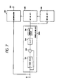
- Fig. 7 shows a third embodiment of this invention which is similar to the embodiment of Figs. 1-5 except that an inter-frame correlation detector 300A includes a horizontal-direction low pass filter 340 disposed between a subtracter 320 and an absolute value circuit 330.
- the horizontal-direction low pass filter 340 removes noise and wrong components from an output signal of the inter-frame correlation detector 300A.
- Fig. 8 shows a fourth embodiment of this invention which is similar to the embodiment of Figs. 1-5 except for an inter-frame correlation detector 300B.
- the inter-frame correlation detector 300B includes a 1-frame period delay device 310, a subtracter 320, a horizontal-direction low pass filter 340, a vertical-direction low pass filter 350, and absolute value circuits 330a and 330b.
- the video signal is applied to the 1-frame period delay device 310 and a first input terminal of the subtracter 320.
- the video signal is delayed by the 1-frame period delay device 310 by a 1-frame period.
- the output signal from the 1-frame period delay device 310 that is, the delayed video signal, is applied to a second input terminal of the subtracter 320.
- the subtracter 320 derives a difference between the non-delayed video signal and the delayed video signal, and outputs a signal representing a difference between two successive frames of the video signal.
- the frame difference signal is fed from the subtracter 320 to the horizontal-direction low pass filter 340.
- the horizontal-direction low pass filter 340 removes noise and wrong components from the frame difference signal.
- the noise-free frame difference signal outputted from the horizontal-direction low pass filter 340 is fed to the vertical-direction low pass filter 350 and the absolute value circuit 330b.
- the noise-free frame difference signal is converted by the absolute value circuit 330b into an absolute frame difference signal representing the absolute value of the noise-free frame difference signal.
- the absolute frame difference signal is outputted from the absolute value circuit 330b to a sudden motion detector 500 so that a sudden vertical motion will be detected on the basis of the absolute frame difference signal by the sudden motion detector 500.
- the vertical-direction low pass filter 340 limits a vertical-frequency band of the noise-free frame difference signal.
- the vertical-band-limited frame difference signal outputted from the vertical-direction low pass filter 340 is fed to the absolute value circuit 330a.
- the vertical-band-limited frame difference signal is converted by the absolute value circuit 330a into an absolute vertical-band-limited frame difference signal representing the absolute value of the vertical-band-limited frame difference signal.
- the absolute vertical-band-limited frame difference signal is outputted from the absolute value circuit 330a to a normal motion detector 400 so that a normal motion will be detected on the basis of the absolute vertical-band-limited frame difference signal by the normal motion detector 400.
- a sudden vertical motion is represented by signal components having high vertical frequencies. Such high vertical frequency components are removed by the vertical-direction low pass filter 350 so that a sudden vertical motion is excluded from motions detectable by the normal motion detector 400.
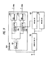
- Fig. 9 shows a fifth embodiment of this invention which is similar to the embodiment of Figs. 1-5 except for design changes indicated hereinafter.
- the embodiment of Fig. 9 is designed so as to process an interlaced-scanning-format video signal such as an NTSC signal or a PAL signal.
- a scanning line interpolator 200A includes a Y-signal/C-signal separator (a Y/C separator) 230, scanning line interpolating sections 210a and 210b, and time base compressors 220a and 220b.
- An input video signal is separated by the Y/C separator 230 into a luminance signal (a Y signal) and a color signal (a C signal).
- the luminance signal is fed to the scanning line interpolating section 210a.
- the luminance signal is fed to a first input terminal of the time base compressor 220a.
- the scanning line interpolating section 210a is similar to the scanning line interpolating section 210 of Figs. 1 and 5, and is controlled by an output signal from a normal motion detector 400.
- the scanning line interpolation section 210a outputs an interpolation signal to a second input terminal of the time base compressor 220a.
- the time base compressor 220a is similar to the time base compressor 220 of Fig.
- the progressive-scanning-format luminance signal outputted from the time base compressor 220a is transmitted via an output terminal 100a.
- the color signal is fed to the scanning line interpolating section 210b.
- the color signal is fed to a first input terminal of the time base compressor 220b.
- the scanning line interpolating section 210b is similar to the scanning line interpolating section 210 of Figs. 1 and 5, and is controlled by the output signal from the normal motion detector 400.
- the scanning line interpolation section 210b outputs an interpolation signal to a second input terminal of the time base compressor 220b.
- the time base compressor 220b is similar to the time base compressor 220 of Fig. 1, and generates a progressive-scanning-format color signal by compressing and combining the color signal and the interpolation signal fed from the devices 230 and 210b.
- the progressive-scanning-format color signal outputted from the time base compressor 220b is transmitted via an output terminal 100b.
- Fig. 10 shows a sixth embodiment of this invention which is similar to the embodiment of Figs. 1-5 except for design changes indicated hereinafter.
- the embodiment of Fig. 10 includes a horizontal (horizontally-extending) outline detector 600 receiving an input video signal.
- the horizontal outline detector 600 functions to detect whether or not the input video signal has a component denoting a horizontally-extending outline or edge of an object. When such a horizontal outline is detected, the horizontal outline detector 600 outputs an "H" signal. When such a horizontal outline is not detected, the horizontal outline detector 600 outputs an "L" signal.
- a sudden motion detector 500A additionally includes an AND gate 530.
- a first input terminal of the AND gate 530 is subjected to an output signal from a pattern detector 520.
- a second input terminal of the AND gate 530 is subjected to the output signal from the horizontal outline detector 600.
- the output signal from the AND gate 530 is fed to a normal motion detector 400 as a sudden motion detection signal.
- the AND gate 530 is open so that the output signal from the pattern detector 520 is transmitted through the AND gate 530 to the normal motion detector 400.
- the output signal from the pattern detector 520 is enabled and is used as a control signal for the normal motion detector 400. In this way, the output signal from the pattern detector 520 is enabled when a horizontal outline is detected.
- the AND gate 530 is closed so that the AND gate 530 outputs an " L" signal to the normal motion detector 400 regardless of the state of the output signal from the pattern detector 520. In this way, the output signal from the pattern detector 520 is ignored when a horizontal outline is not detected. This process improves the reliability of the detection of a sudden vertical motion.
- the horizontal outline detector 600 includes 1-line period delay devices 601a and 601b, subtracters 602a and 602b, low pass filters 603a and 603b, absolute value circuits 604a and 604b, a larger value selector 605, and a comparator 606.
- the input video signal at the point "a" of Fig. 11 is fed to the 1-line period delay device 601a and a first input terminal of the subtracter 602a.
- the waveform of the input video signal is denoted by "a" in Fig. 12.
- the input video signal is delayed by the 1-line period delay device 601a by a 1-line period.
- the output signal from the 1-line period delay device 601a which appears at the point "b" of Fig.
- the subtracter 602a executes the subtraction between the input video signal and the output signal from the 1-line period delay device 601a, and outputs a resultant signal to the point "d" of Fig. 11.
- the waveform of the output signal from the subtracter 602a is denoted by "d” in Fig. 12.
- the output signal from the subtracter 602a is processed by the low pass filter 603a.
- the output signal from the low pass filter 603a is converted by the absolute value circuit 604a into an absolute value signal which appears at the point "f" of Fig. 11 and which represents the absolute value of the output signal from the low pass filter 603a.
- the waveform of the absolute value signal generated by the absolute value circuit 604a is denoted by "f" in Fig. 12.
- the absolute value signal is fed from the absolute value circuit 604a to a first input terminal of the larger value selector 605.
- the output signal from the 1-line period delay device 601a (see “b” of Fig. 12) is fed to a first input terminal of the subtracter 602b.
- the output signal from the 1-line period delay device 601a is delayed by the 1-line period delay device 601b by a 1-line period.
- the output signal from the 1-line period delay device 601b which appears at the point "c" of Fig. 11 is fed to a second input terminal of the subtracter 602b.
- the waveform of the output signal from the 1-line period delay device 601b is denoted by "c" in Fig. 12.
- the subtracter 602b executes the subtraction between the output signals from the 1-line period delay devices 601a and 601b, and outputs a resultant signal to the point "e" of Fig. 11.
- the waveform of the output signal from the subtracter 602b is denoted by “e” in Fig. 12.
- the output signal from the subtracter 602b is processed by the low pass filter 603b.
- the output signal from the low pass filter 603b is converted by the absolute value circuit 604b into an absolute value signal which appears at the point "g" of Fig. 11 and which represents the absolute value of the output signal from the low pass filter 603b.
- the waveform of the absolute value signal generated by the absolute value circuit 604b is denoted by "g” in Fig. 12.
- the absolute value signal is fed from the absolute value circuit 604b to a second input terminal of the larger value selector 605.
- the larger value selector 605 selects one of the two absolute value signals which represents the larger absolute value, and outputs the selected absolute value signal to the point "h" of Fig. 11.
- the waveform of the selected absolute value signal is denoted by "h” in Fig. 12.
- the selected absolute value signal is fed from the larger value selector 605 to a first input terminal of the comparator 606.
- a second input terminal of the comparator 606 is subjected to a signal representative of a predetermined threshold which is generated by a suitable device (not shown).
- the comparator 606 compares the absolute value signal with the threshold signal, and outputs a resultant signal to the point of Fig. 11.
- the waveform of the output signal from the comparator 606 is denoted by "i" in Fig. 12.
- the "H” output signal from the comparator 606 represents the presence of a horizontal outline of an object.
- the “L” output signal from the comparator 606 represents the absence of a horizontal outline of an object.
- the output signal from the comparator 606 is used as the output signal from the horizontal outline detector 600.
- Fig. 13 shows a seventh embodiment of this invention which is similar to the embodiment of Figs. 10-12 except for design changes indicated hereinafter.
- the AND gate 530 (see Fig. 10) is removed and the output signal form a pattern detector 520 is directly applied to a normal motion detector 400 as in the embodiment of Figs. 1-5.
- a sudden motion detector 500B includes a threshold setting device 540 receiving the output signal from a horizontal outline detector 600.
- the threshold setting device 540 includes a selector 541 having two input terminals subjected to signals representative of predetermined thresholds ThL and ThH which are generated by suitable devices (not shown).
- a control terminal of the selector 541 receives the output signal from the horizontal outline detector 600.
- the selector 541 selects one of the threshold signals in response to the output signal from the horizontal outline detector 600, and outputs the selected threshold signal to a comparator 510.
- the threshold ThL is smaller than the threshold ThH.
- the selector 541 selects the signal of the larger threshold ThH and feeds the signal of the larger threshold ThH to the comparator 510.
- the selector 541 selects the signal of the smaller threshold ThL and feeds the signal of the smaller threshold ThL to the comparator 510.
Applications Claiming Priority (4)
| Application Number | Priority Date | Filing Date | Title |
|---|---|---|---|
| JP227693/89 | 1989-09-01 | ||
| JP1227693A JPH0389791A (ja) | 1989-09-01 | 1989-09-01 | 偽動き信号検出回路 |
| JP1325050A JPH082101B2 (ja) | 1989-12-14 | 1989-12-14 | 動き適応走査線補間回路 |
| JP325050/89 | 1989-12-14 |
Publications (3)
| Publication Number | Publication Date |
|---|---|
| EP0415325A2 true EP0415325A2 (fr) | 1991-03-06 |
| EP0415325A3 EP0415325A3 (en) | 1992-04-22 |
| EP0415325B1 EP0415325B1 (fr) | 1995-11-08 |
Family
ID=26527818
Family Applications (1)
| Application Number | Title | Priority Date | Filing Date |
|---|---|---|---|
| EP90116396A Expired - Lifetime EP0415325B1 (fr) | 1989-09-01 | 1990-08-27 | Appareil de traitement de signal vidéo |
Country Status (4)
| Country | Link |
|---|---|
| US (1) | US5095354A (fr) |
| EP (1) | EP0415325B1 (fr) |
| KR (1) | KR930006531B1 (fr) |
| DE (1) | DE69023434T2 (fr) |
Cited By (6)
| Publication number | Priority date | Publication date | Assignee | Title |
|---|---|---|---|---|
| EP0448164A2 (fr) * | 1990-03-21 | 1991-09-25 | Philips Electronics Uk Limited | Méthode et dispositif pour le traitement d'un signal |
| EP0598333A1 (fr) * | 1992-11-19 | 1994-05-25 | THOMSON multimedia | Méthode et appareil pour la conversion vers le haut de la fréquence image |
| US5504531A (en) * | 1992-11-19 | 1996-04-02 | Thomson Consumer Electronics, S.A. | Method and apparatus for field rate up-conversion |
| EP0740468A1 (fr) * | 1995-04-27 | 1996-10-30 | Texas Instruments Incorporated | Améliorations apportées à une télévision à balayage progressif |
| WO2003019933A1 (fr) * | 2001-08-24 | 2003-03-06 | Ps Miro Holdings Inc. & Co. Kg | Procede et dispositif de reconnaissance d'un mouvement dans une image |
| WO2005091625A1 (fr) * | 2004-03-17 | 2005-09-29 | Koninklijke Philips Electronics N.V. | Desentrelacement |
Families Citing this family (22)
| Publication number | Priority date | Publication date | Assignee | Title |
|---|---|---|---|---|
| KR930009181B1 (ko) * | 1990-12-22 | 1993-09-23 | 삼성전자 주식회사 | 영상신호의 2차원 경사상관 보간방법 및 회로 |
| GB2252468B (en) * | 1991-02-04 | 1994-10-19 | Sony Broadcast & Communication | Television standards converters |
| GB2252467B (en) * | 1991-02-04 | 1994-11-23 | Sony Broadcast & Communication | Television standards converters |
| US5386249A (en) * | 1992-01-22 | 1995-01-31 | Samsung Electronics Co., Ltd. | Video motion detector with full-band response except for diagonal spatial frequencies |
| US5428397A (en) * | 1993-05-07 | 1995-06-27 | Goldstar Co., Ltd. | Video format conversion apparatus for converting interlaced video format into progressive video format using motion-compensation |
| JPH06351002A (ja) * | 1993-06-08 | 1994-12-22 | Matsushita Electric Ind Co Ltd | 動き信号検出方法およびこれを用いた映像信号処理装置 |
| US5473381A (en) * | 1993-08-07 | 1995-12-05 | Goldstar Co., Ltd. | Apparatus for converting frame format of a television signal to a display format for a high definition television (HDTV) receiver |
| JP3266416B2 (ja) * | 1994-04-18 | 2002-03-18 | ケイディーディーアイ株式会社 | 動き補償フレーム間符号化復号装置 |
| JP3500751B2 (ja) * | 1995-01-20 | 2004-02-23 | ソニー株式会社 | 画像信号処理装置及び撮像装置 |
| JPH09163373A (ja) * | 1995-12-08 | 1997-06-20 | Toshiba Corp | 雑音低減装置 |
| US6141056A (en) * | 1997-08-08 | 2000-10-31 | Sharp Laboratories Of America, Inc. | System for conversion of interlaced video to progressive video using horizontal displacement |
| KR100252943B1 (ko) * | 1997-09-11 | 2000-04-15 | 구자홍 | 스캔컨버터회로 |
| KR100252949B1 (ko) * | 1997-09-11 | 2000-04-15 | 구자홍 | 스캔컨버터회로 |
| US6262773B1 (en) | 1997-09-15 | 2001-07-17 | Sharp Laboratories Of America, Inc. | System for conversion of interlaced video to progressive video using edge correlation |
| US7536706B1 (en) | 1998-08-24 | 2009-05-19 | Sharp Laboratories Of America, Inc. | Information enhanced audio video encoding system |
| US6348949B1 (en) * | 1998-12-22 | 2002-02-19 | Intel Corporation | Deinterlacing a video signal using a motion detector |
| US7035475B1 (en) * | 1999-06-17 | 2006-04-25 | Raytheon Company | Non-traditional adaptive non-uniformity compensation (ADNUC) system employing adaptive feedforward shunting and operating methods therefor |
| US7647340B2 (en) | 2000-06-28 | 2010-01-12 | Sharp Laboratories Of America, Inc. | Metadata in JPEG 2000 file format |
| CN1278553C (zh) * | 2003-05-23 | 2006-10-04 | 华亚微电子(上海)有限公司 | 一种像素静止检测的多窗口多阈值方法 |
| KR100545379B1 (ko) * | 2004-03-09 | 2006-01-24 | 삼성전자주식회사 | 휘도/색차 성분 분리 기능이 내장된 광기록재생 장치 |
| GB2431803A (en) * | 2005-10-31 | 2007-05-02 | Sony Uk Ltd | Alias avoidance in image processing |
| JP4973031B2 (ja) * | 2006-07-03 | 2012-07-11 | ソニー株式会社 | ノイズ抑圧方法、ノイズ抑圧方法のプログラム、ノイズ抑圧方法のプログラムを記録した記録媒体及びノイズ抑圧装置 |
Citations (5)
| Publication number | Priority date | Publication date | Assignee | Title |
|---|---|---|---|---|
| US4275418A (en) * | 1978-09-14 | 1981-06-23 | Micro Consultants Limited | Video noise reduction systems |
| EP0163513A1 (fr) * | 1984-05-29 | 1985-12-04 | Rca Licensing Corporation | Récépteur de télévision sans entrelacement de lignes |
| GB2175770A (en) * | 1985-05-29 | 1986-12-03 | Rca Corp | Progressive scan processor |
| EP0241854A2 (fr) * | 1986-04-09 | 1987-10-21 | Hitachi, Ltd. | Circuit de traitement de signal vidéo du type adapté au mouvement |
| EP0318760A2 (fr) * | 1987-12-02 | 1989-06-07 | Blaupunkt-Werke GmbH | Récepteur de télévision avec un dispositif de suppression des perturbations de scintillement |
Family Cites Families (4)
| Publication number | Priority date | Publication date | Assignee | Title |
|---|---|---|---|---|
| US4612567A (en) * | 1984-05-03 | 1986-09-16 | Rca Corporation | Television receiver using non-interlaced scanning format with vertical detail enhancement and motion compensation |
| US4608594A (en) * | 1984-05-25 | 1986-08-26 | Rca Corporation | Television receiver using non-interlaced scanning format with motion compensation |
| US4868650A (en) * | 1988-03-07 | 1989-09-19 | Rca Licensing Corporation | Circuitry for expanding the effect of a video control signal in multiple dimensions |
| GB2231226B (en) * | 1989-04-27 | 1993-09-22 | Sony Corp | Motion dependent video signal processing |
-
1990
- 1990-08-10 US US07/565,392 patent/US5095354A/en not_active Expired - Lifetime
- 1990-08-27 EP EP90116396A patent/EP0415325B1/fr not_active Expired - Lifetime
- 1990-08-27 DE DE69023434T patent/DE69023434T2/de not_active Expired - Fee Related
- 1990-08-31 KR KR1019900013656A patent/KR930006531B1/ko not_active IP Right Cessation
Patent Citations (5)
| Publication number | Priority date | Publication date | Assignee | Title |
|---|---|---|---|---|
| US4275418A (en) * | 1978-09-14 | 1981-06-23 | Micro Consultants Limited | Video noise reduction systems |
| EP0163513A1 (fr) * | 1984-05-29 | 1985-12-04 | Rca Licensing Corporation | Récépteur de télévision sans entrelacement de lignes |
| GB2175770A (en) * | 1985-05-29 | 1986-12-03 | Rca Corp | Progressive scan processor |
| EP0241854A2 (fr) * | 1986-04-09 | 1987-10-21 | Hitachi, Ltd. | Circuit de traitement de signal vidéo du type adapté au mouvement |
| EP0318760A2 (fr) * | 1987-12-02 | 1989-06-07 | Blaupunkt-Werke GmbH | Récepteur de télévision avec un dispositif de suppression des perturbations de scintillement |
Cited By (8)
| Publication number | Priority date | Publication date | Assignee | Title |
|---|---|---|---|---|
| EP0448164A2 (fr) * | 1990-03-21 | 1991-09-25 | Philips Electronics Uk Limited | Méthode et dispositif pour le traitement d'un signal |
| EP0448164A3 (en) * | 1990-03-21 | 1992-09-09 | Philips Electronics Uk Ltd | Method and apparatus for processing a signal |
| EP0598333A1 (fr) * | 1992-11-19 | 1994-05-25 | THOMSON multimedia | Méthode et appareil pour la conversion vers le haut de la fréquence image |
| US5504531A (en) * | 1992-11-19 | 1996-04-02 | Thomson Consumer Electronics, S.A. | Method and apparatus for field rate up-conversion |
| EP0740468A1 (fr) * | 1995-04-27 | 1996-10-30 | Texas Instruments Incorporated | Améliorations apportées à une télévision à balayage progressif |
| US6320620B1 (en) | 1995-04-27 | 2001-11-20 | Texas Instruments Incorporated | Low cost progressive scan television with special features |
| WO2003019933A1 (fr) * | 2001-08-24 | 2003-03-06 | Ps Miro Holdings Inc. & Co. Kg | Procede et dispositif de reconnaissance d'un mouvement dans une image |
| WO2005091625A1 (fr) * | 2004-03-17 | 2005-09-29 | Koninklijke Philips Electronics N.V. | Desentrelacement |
Also Published As
| Publication number | Publication date |
|---|---|
| DE69023434D1 (de) | 1995-12-14 |
| EP0415325A3 (en) | 1992-04-22 |
| DE69023434T2 (de) | 1996-04-04 |
| KR910007362A (ko) | 1991-04-30 |
| KR930006531B1 (ko) | 1993-07-16 |
| US5095354A (en) | 1992-03-10 |
| EP0415325B1 (fr) | 1995-11-08 |
Similar Documents
| Publication | Publication Date | Title |
|---|---|---|
| US5095354A (en) | Scanning format converter with motion compensation | |
| JP4633108B2 (ja) | フィルムソース映像検出 | |
| EP0391094A2 (fr) | Dispositif de doublage de lignes de balayage de télévision avec un filtre de valeur moyenne temporelle | |
| CA1264372A (fr) | Circuit de traitement de signaux de television | |
| JPS62276983A (ja) | 逐次走査システム | |
| JPS6390987A (ja) | 動き検出回路 | |
| KR920006168B1 (ko) | 주사형식 변환방식의 텔레비젼 신호 전송/수신 시스템 | |
| US5488422A (en) | Video scan converter including the modification of spatially interpolated pixels as a function of temporal detail and motion | |
| US5497203A (en) | Motion detection circuit for high definition television based on muse | |
| EP0487186B1 (fr) | Circuit de détection d'un signal de mouvement | |
| JPH03190473A (ja) | ビデオ信号処理装置 | |
| JPH0832025B2 (ja) | 動き摘応型信号処理回路 | |
| JPS62175091A (ja) | カラ−テレビジヨン信号処理回路 | |
| EP0772351B1 (fr) | Détection de mouvement pour signaux vidéo entrelacés | |
| EP0488498B1 (fr) | Circuit de détection du signal de mouvement | |
| JP2580891B2 (ja) | 走査線補間回路 | |
| JPS6251392A (ja) | テレビジヨン信号処理回路 | |
| JP2765012B2 (ja) | 補間信号形成回路 | |
| JPH02260889A (ja) | 画像信号処理装置 | |
| JPH03185984A (ja) | 動き適応走査線補間回路 | |
| US5161016A (en) | Method of interpolating an image signal using a slope correlation and a circuit thereof | |
| JP2567879B2 (ja) | 画像の垂直エッジ検出回路 | |
| JP3025736B2 (ja) | 映像信号中における動き検出装置 | |
| JP2502054B2 (ja) | 画像信号変換装置 | |
| JP2003169300A (ja) | 映像信号処理装置 |
Legal Events
| Date | Code | Title | Description |
|---|---|---|---|
| PUAI | Public reference made under article 153(3) epc to a published international application that has entered the european phase |
Free format text: ORIGINAL CODE: 0009012 |
|
| 17P | Request for examination filed |
Effective date: 19900827 |
|
| AK | Designated contracting states |
Kind code of ref document: A2 Designated state(s): DE FR GB |
|
| PUAL | Search report despatched |
Free format text: ORIGINAL CODE: 0009013 |
|
| AK | Designated contracting states |
Kind code of ref document: A3 Designated state(s): DE FR GB |
|
| 17Q | First examination report despatched |
Effective date: 19940217 |
|
| GRAA | (expected) grant |
Free format text: ORIGINAL CODE: 0009210 |
|
| AK | Designated contracting states |
Kind code of ref document: B1 Designated state(s): DE FR GB |
|
| REF | Corresponds to: |
Ref document number: 69023434 Country of ref document: DE Date of ref document: 19951214 |
|
| ET | Fr: translation filed | ||
| PLBE | No opposition filed within time limit |
Free format text: ORIGINAL CODE: 0009261 |
|
| STAA | Information on the status of an ep patent application or granted ep patent |
Free format text: STATUS: NO OPPOSITION FILED WITHIN TIME LIMIT |
|
| 26N | No opposition filed | ||
| PGFP | Annual fee paid to national office [announced via postgrant information from national office to epo] |
Ref country code: FR Payment date: 20010810 Year of fee payment: 12 |
|
| PGFP | Annual fee paid to national office [announced via postgrant information from national office to epo] |
Ref country code: DE Payment date: 20010820 Year of fee payment: 12 |
|
| PGFP | Annual fee paid to national office [announced via postgrant information from national office to epo] |
Ref country code: GB Payment date: 20010822 Year of fee payment: 12 |
|
| REG | Reference to a national code |
Ref country code: GB Ref legal event code: IF02 |
|
| PG25 | Lapsed in a contracting state [announced via postgrant information from national office to epo] |
Ref country code: GB Free format text: LAPSE BECAUSE OF NON-PAYMENT OF DUE FEES Effective date: 20020827 |
|
| PG25 | Lapsed in a contracting state [announced via postgrant information from national office to epo] |
Ref country code: DE Free format text: LAPSE BECAUSE OF NON-PAYMENT OF DUE FEES Effective date: 20030301 |
|
| GBPC | Gb: european patent ceased through non-payment of renewal fee |
Effective date: 20020827 |
|
| PG25 | Lapsed in a contracting state [announced via postgrant information from national office to epo] |
Ref country code: FR Free format text: LAPSE BECAUSE OF NON-PAYMENT OF DUE FEES Effective date: 20030430 |
|
| REG | Reference to a national code |
Ref country code: FR Ref legal event code: ST |