EP0415076A2 - Schmutzsauger - Google Patents
Schmutzsauger Download PDFInfo
- Publication number
- EP0415076A2 EP0415076A2 EP90114232A EP90114232A EP0415076A2 EP 0415076 A2 EP0415076 A2 EP 0415076A2 EP 90114232 A EP90114232 A EP 90114232A EP 90114232 A EP90114232 A EP 90114232A EP 0415076 A2 EP0415076 A2 EP 0415076A2
- Authority
- EP
- European Patent Office
- Prior art keywords
- motor
- flow
- cooling air
- housing
- components
- Prior art date
- Legal status (The legal status is an assumption and is not a legal conclusion. Google has not performed a legal analysis and makes no representation as to the accuracy of the status listed.)
- Granted
Links
- 238000001816 cooling Methods 0.000 claims abstract description 25
- 238000004804 winding Methods 0.000 description 4
- 230000010354 integration Effects 0.000 description 2
- 238000007789 sealing Methods 0.000 description 2
- 238000010276 construction Methods 0.000 description 1
- 230000007547 defect Effects 0.000 description 1
- 238000009413 insulation Methods 0.000 description 1
- 230000008439 repair process Effects 0.000 description 1
- 238000011144 upstream manufacturing Methods 0.000 description 1
Images


Classifications
-
- A—HUMAN NECESSITIES
- A47—FURNITURE; DOMESTIC ARTICLES OR APPLIANCES; COFFEE MILLS; SPICE MILLS; SUCTION CLEANERS IN GENERAL
- A47L—DOMESTIC WASHING OR CLEANING; SUCTION CLEANERS IN GENERAL
- A47L9/00—Details or accessories of suction cleaners, e.g. mechanical means for controlling the suction or for effecting pulsating action; Storing devices specially adapted to suction cleaners or parts thereof; Carrying-vehicles specially adapted for suction cleaners
- A47L9/28—Installation of the electric equipment, e.g. adaptation or attachment to the suction cleaner; Controlling suction cleaners by electric means
- A47L9/2836—Installation of the electric equipment, e.g. adaptation or attachment to the suction cleaner; Controlling suction cleaners by electric means characterised by the parts which are controlled
- A47L9/2842—Suction motors or blowers
Definitions
- the invention relates to a vacuum cleaner with an electric motor, which is fastened between a lower carrier plate and an upper clamping plate, further with electrical or electronic components fastened to circuit boards in the flow housing and with an intake duct and an exhaust duct for the engine cooling air.
- the invention is therefore based on the object of proposing such a vacuum cleaner which is distinguished in particular by a significantly increased service life of the electrical and electronic components.
- the components should also be arranged in a housing in a space-saving and easily replaceable manner.
- the invention is characterized in that when the electric motor is designed as a commutatorless DC motor, at least one of the boards with its components is arranged in the intake duct for the engine cooling air, the intake duct in runs essentially U-shaped with a first leg in the direction of flow, an adjoining horizontal section and an adjoining second leg which is connected airtight to the upper part of the electric motor.
- circuit boards with their components can thus be accommodated in the first leg, in the horizontal section and / or in the second leg, and the engine cooling air flows directly through them and cools them well. They can also be easily replaced, as will be explained in more detail below.
- the parts are also easy to replace.
- the intake duct is placed with its one nozzle (first leg) on the already existing intake opening for the suction of the cooling air for the engine on the motor clamping plate and with the other nozzle (second leg) it is directly connected to the stator of the with the interposition of a sealing ring Motor attached and connected to it in an air-tight manner.
- control electronics In the event of defects and repairs, the entire unit with the entire control electronics can be used. can be easily replaced.
- the control electronics are fully located in the cooling air flow for the engine, upstream of the engine.
- this also ensures that vacuum cleaners which have been in operation so far can be retrofitted with such a unit.
- the existing AC motor simply has to be replaced by the new type of commutatorless DC motor, and the flow housing with the electronics integrated therein is then simply placed on the already existing motor chuck.
- Each motor is then connected to such a flow housing, with the control of each motor being implemented separately via the circuit electronics arranged in the respective flow housing.
- the motor-side socket of the housing with the electronics integrated on it is air-tight with the upper part, i.e. So is connected to the fixed winding part of the motor and that an outlet cross-section is formed around the motor in the clamping plate, so that this ensures that the cooling air is guided inward into the motor through the flow housing, flows through the motor to the Windings flow past, is diverted by approx. 1800 and flows out in the opposite direction to the incoming cooling air on the outside of the flow-through housing, appropriate sound insulation mats being arranged here in the outflow channel formed by the clamping plate and hood in order to dampen the engine noise.
- this exhaust air / air flow is then discharged via labyrinth channels arranged in the hood of the vacuum cleaner.
- corresponding protruding angles are provided on the side wall of the flow channel, which have bores through which screws pass, which screws are screwed into the top of the clamping plate.
- angles in the flow housing itself can be integrated, the flow housing having, for example, bores in its base plate, through which screws can be screwed then also reach into the clamping plate.
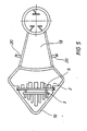
- An electric motor 31 is clamped in an easily replaceable manner between a lower carrier plate 32 and an upper clamping plate 33, the electric motor being held in a vibration-damped manner via rubber elements 34. From Figure 1, the turbine 35 of the vacuum cleaner can also be seen, which is placed directly below the actual electric motor 31.
- the flow of the engine cooling air is indicated in FIG. 1 with MK, the flow of the engine exhaust air with MA, the flow of the suction supply air with SZ and the flow of the suction exhaust air with SA.
- a flow housing 1 for the engine cooling air according to FIG. 3 is open at the top and has an upper edge 21.
- the upper cover of this housing 1 with respect to the upper edge 21 is formed by the inside of the hood of the vacuum cleaner, not shown. This means that the housing 1 is closed on all sides and only has one connector 2 and the other connector 17.
- the wall 19 which is approximately angled in plan view, is omitted and this wall 19 itself is formed by the wall of the hood or the clamping plate of the vacuum cleaner.
- the flow-through housing 1 is only flowed through by the engine cooling air.
- the turbine intake air and the turbine exhaust air are routed separately in the exhaust air ducts between the clamping plate and the carrier plate.
- the present invention is therefore about the guidance of the engine cooling air and the arrangement of the electronic circuit parts in the area of this flow housing.
- FIG 3 is shown schematically that the housing essentially (see Figure 4 and Figure 5) consists of two connecting pieces or legs 2, 17, which form a mutual distance from each other.
- a heat sink 3 with cooling fins 4 is arranged in the connecting piece 2, transistors 8 being firmly connected to the heat sink 3 on the side faces of this heat sink.
- This heat sink is thus fully in the flow of the intake cooling air, which enters the nozzle 2 in the direction of arrow 12 from below.
- the cooling air occurs in several cross sections, namely once in the gap 9 between the heat sink 3 and the outer wall 19 of the housing, further in the gap 10 between the back of the heat sink 3 and the back of a circuit board 6 and further in the gap 11 between the front of the Board 6 and the inner wall of the connector 2.
- the wall 19 can be omitted and appropriate sealing measures are then provided at position 22, because then in this area the connector 2 rests air-tight on the inside of the hood and the connector 2 on the one hand through the wall of the hood and on the other hand through remaining walls of the housing 1 is formed.
- This board 15 essentially carries the mains rectifier 16 with heat sinks, cooling fins and the like. Components to be cooled more.
- the air then flows in the direction of the arrow 18 and then flows into the nozzle 17, where the nozzle on its lower edge 23 is also air-tight is connected to the fixed part of the motor, so that the air in the direction of arrow 18 then flows through the winding of the motor.
- the electronics to be cooled could also be arranged directly on the clamping plate and in the incoming cooling air flow of the motor.
- appropriate electronic parts to be cooled can also be arranged in this area, such as, for. B. a mains interference filter, an automatic switch-on and switch-off for switching the vacuum motor on and off in the event of a fault, and an automatic switch-off for switching off a tool, which is then switched off when the vacuum cleaner falls below a certain minimum volume flow.
Landscapes
- Engineering & Computer Science (AREA)
- Mechanical Engineering (AREA)
- Motor Or Generator Cooling System (AREA)
- Motor Or Generator Frames (AREA)
- Filters For Electric Vacuum Cleaners (AREA)
- Electric Suction Cleaners (AREA)
- Electric Vacuum Cleaner (AREA)
- Brushless Motors (AREA)
- Electrical Discharge Machining, Electrochemical Machining, And Combined Machining (AREA)
- Crystals, And After-Treatments Of Crystals (AREA)
Abstract
Description
- Die Erfindung betrifft einen Schmutzsauger mit einem Elektromotor, der zwischen einer unteren Trägerplatte und einer oberen Spannplatte befestigt ist, ferner mit auf Platinen im Durchflußgehäuse befestigten elektrischen bzw. elektronischen Bauelementen und mit einem Ansaugkanal und einem Abluftkanal für die Motorkühlluft.
- Derartige Schmutzsauger sind bekannt. Die Elektromotoren sind hierbei als asynchron-Motoren ausgebildet. Sie benötigen daher eine verhältnismäßig große Leistungselektronik und Ansteuerelektronik, die üblicherweise auf zwei getrennten Platinen im Euro-Format untergebracht waren. Bedingt durch diese Größe war es nicht möglich, die Platinen mit ihren Bauelementen unmittelbar im Kühlluftstrom für die Motorkühlung unterzubringen. Die Bauelemente haben sich also verhältnismäßig schnell und stark erwärmt, worunter wiederum ihre Lebensdauer fühlbar gelitten hat.
- Der Erfindung liegt daher die Aufgabe zugrunde, einen derartigen Schmutzsauger vorzuschlagen, der sich insbesondere durch eine wesentlich erhöhte Lebensdauer der elektrischen und elektronischen Bauelemente auszeichnet. Auch sollen die Bauelemente platzsparend und leicht auswechselbar in einem Gehäuse angeordnet sein.
- Zur Lösung dieser Aufgabe ist die Erfindung dadurch gekennzeichnet, daß bei Ausbildung des Elektromotors als kommutatorloser Gleichstrommotor wenigstens eine der Platinen mit ihren Bauelementen in dem Ansaugkanal für die Motorkühlluft angeordnet ist, wobei der Ansaugkanal im wesentlichen U-förmig verläuft mit einem in Strömungsrichtung ersten Schenkel, einem sich daran anschließenden waagerechten Abschnitt und einem sich daran anschließenden zweiten Schenkel, der luftdicht an das Oberteil des Elektromotors angeschlossen ist.
- Man kann somit die Platinen mit ihren Bauelementen im ersten Schenkel, im waagerechten Abschnitt und/oder im zweiten Schenkel unterbringen und sie werden dort unmittelbar von der Motorkühlluft durchströmt und gut gekühlt. Sie können auch leicht ausgewechselt werden, wie dies weiter unten noch näher erläutert wird.
- Die Verwendung des kommutatorlosen Gleichstrommotors anstelle der sonst verwendeten asynchron-Motoren bringt den Vorteil mit sich, daß ein wesentlich kleinerer Elektromotor verwendet werden kann, der aufgrund seines geringeren Gewichts ein anderes Schwingungsverhalten hat und eine Leistungsansteuerung mit Platinen benötigt, die wesentlich kleiner sind als die herkömmlichen Platinen für die Leistungsansteuerung von asynchron-Motoren. Diese Merkmale zusammen ergeben also die Möglichkeit, die Platinen jetzt direkt in der Motorkühlluft anzuordnen, wodurch sich die angestrebte wesentliche Verlängerung der Lebensdauer dieser Bauteile ergibt.
- Die Teile sind auch leicht auswechselbar.
- Zur Montage wird der Ansaugkanal mit seinem einen Stutzen (ersten Schenkel) auf die bereits vorhandene Ansaugöffnung für die Ansaugung der Kühlluft für den Motor auf die Motorspannplatte aufgesetzt und mit dem anderen Stutzen (zweiten Schenkel) wird er unter Zwischenschaltung eines Dichtungsringes unmittelbar auf den Stator des Motors aufgesetzt und luftschlüssig mit diesem verbunden.
- Bei eventuellen Defekten und Reparaturfällen kann somit die gesamte Einheit mit der gesamten Steuerungselektronik. leicht ausgewechselt werden. Die Steuerungselektronik ist voll im Kühlluftstrom für den Motor angeordnet, und zwar stromaufwärts des Motors.
- Wesentlich hierbei ist, daß wegen der Integration der gesamten Steuerelektronik und aller elektrischen Versorgungsbauteile nur wenige Kabelzuführungen notwendig sind. Im Prinzip bedarf es nur einer zweiadrigen Leitung zur Wechselstromzuführung und einer zweiadrigen Leitung zur Stromversorgung für die Wicklung des Motors sowie einer weiteren Steuerleitung für die Zuführung der entsprechenden Steuersignale zum elektronisch geregelten Motor.
- Auch damit ist die leichte Auswechselbarkeit des gesamten Durchflußgehäuses gewährleistet.
- Wegen des kompakten Aufbaus dieses Durchflußgehäuses ist damit auch gewährleistet, daß bisher im Betrieb befindliche Staubsauger mit einer derartigen Einheit nachgerüstet werden können.
- Hierzu muß einfach der bereits vorhandene Wechselstrommotor gegen den neuartigen kommutatorlosen Gleichstrommotor ausgetauscht werden und es wird dann auf die bereits konstruktiv vorhandene Motorspannplatte einfach das Durchflußgehäuse mit der darin integrierten Elektronik aufgesetzt.
- Eine gleiche Ausrüstung mit dem beschriebenen Durchflußgehäuse gilt nicht nur für eine Ein-Motorausführung sondern auch für Staubsauger, die mehrere parallel nebeneinander und getrennt voneinander betriebene Motoren aufweisen.
- Jeder Motor wird dann mit einem derartigen Durchflußgehäuse verbunden, wobei die Steuerung von jedem Motor separat über die in dem jeweiligen Durchflußgehäuse angeordnete Schaltungselektronik verwirklicht wird.
- Wichtig hierbei ist, daß der motorseitige Stutzen des Gehäuses mit der daran integrierten Elektronik luftschlüssig mit dem oberen Teil, d.h. also mit dem feststehenden Wicklungsteil des Motors verbunden ist und daß rings um den Motor in der Spannplatte noch ein Auslaßquerschnitt gebildet ist, so daß hierdurch gewährleistet ist, daß über das Durchflußgehäuse die Kühlluft nach innen in den Motor geführt wird, den Motor durchströmt, an den Wicklungen vorbei strömt, um ca. 1800 umgelenkt wird und in Gegenrichtung zur einströmenden Kühlluft an der Außenseite des Durchflußgehäuses herausströmt, wobei hier im von Spannplatte und Haube gebildeten Ausströmkanal entsprechende Schalldämmatten angeordnet sind, um das Motorgeräusch zu dämpfen.
- In an sich bekannter Weise wird dann dieser Abluft-Luftstrom über in der Haube des Schmutzsaugers angeordnete Labyrinthkanäle abgeführt.
- Die Befestigung des genannten Durchflußkanals erfolgt lediglich mit zwei Schrauben.
- In einer ersten Ausführungsform kann hierbei vorgesehen sein, daß an der Seitenwand des Durchflußkanals entsprechende abstehende Winkel vorgesehen sind, welche Bohrungen aufweisen, die von Schrauben durchgriffen werden, welche Schrauben in die Oberseite der Spannplatte eingeschraubt sind.
- Ebenso können die Winkel im Durchflußgehäuse selbst integriert werden, wobei das Durchflußgehäuse z.B. in seiner Bodenplatte Bohrungen aufweist, durch welche Schrauben hindurchgeschraubt werden können, die dann ebenfalls in die Spannplatte hineingreifen.
- Es handelt sich also um eine leicht lösbare Befestigung, weil - wie gesagt - dieses Durchflußgehäuse lediglich auf der einen Seite auf dem Ansauggitter der Spannplatte für die Ansaugung des Kühlluftstromes aufgesetzt wird und auf der anderen Seite - wie beschrieben - luftschlüssig mit dem feststehenden Teil des Motors verbunden wird.
- Die Erfindung wird im folgenden anhand von Ausführungsbeispielen näher erläutert, aus denen sich weitere wichtige Merkmale ergeben.
- Es zeigen:
- Figur 1: eine Schnittansicht durch die hier interessierenden wesentlichen Bauteile eines Schmutzsaugers nach der Erfindung in einem Schnitt längs der Linie A-B von Figur 2;
- Figur 2: eine Draufsicht auf Figur 1, wobei zur Verdeutlichung Teile fortgelassen wurden;
- Figur 3: eine Schnittansicht entsprechend der Figur 1 bei einer etwas abgewandelten Ausführungsform zur Erläuterung von Einzelheiten;
- Figur 4: eine Draufsicht auf Figur 3;
- Figur 5: eine Ansicht entsprechend Figur 4 bei einer abermals abgewandelten Ausführungsform.
- Zunächst sei der grundsätzliche Aufbau der hier interessierenden wesentlichen Teile des Schmutzsaugers nach der Erfindung anhand der Figuren 1 und 2 erläutert.
- In einem Gehäuse ist ein Elektromotor 31 zwischen einer unteren Trägerplatte 32 und einer oberen Spannplatte 33 leicht auswechselbar eingespannt, wobei der Elektromotor über Gummielemente 34 schwingungsgedämpft gehalten ist. Aus Figur 1 ist auch noch die Turbine 35 des Schmutzsaugers ersichtlich, die direkt unten auf den eigentlichen Elektromotor 31 aufgesetzt ist.
- Die Strömung der Motorkühlluft ist in Figur 1 mit MK angegeben, die Strömung der Motorabluft mit MA, die Strömung der Saugzuluft mit SZ und die Strömung der Saugabluft mit SA.
- Ein Durchflußgehäuse 1 für die Motorkühlluft entsprechend Figur 3 ist oben offen und weist einen oberen Rand 21 auf. Die obere Abdeckung dieses Gehäuses 1 bezüglich des oberen Randes 21 wird durch die Innenseite der nicht näher dargestellten Haube des Schmutzsaugers gebildet. Das heißt, das Gehäuse 1 ist also an allen Seiten geschlossen und weist lediglich den einen Stutzen 2 und den anderen Stutzen 17 auf.
- Zur Vereinfachung der Gehäusekonstruktion des Gehäuses 1 kann es hierbei auch vorgesehen sein, daß die in Draufsicht etwa abgewinkelte Wandung 19 entfällt und diese Wandung 19 selbst durch die Wandung der Haube oder der Spannplatte des Schmutzsaugers gebildet wird.
- Das Durchflußgehäuse 1 wird nur von der Motorkühlluft durchströmt. Die Turbinenansaugluft und die Turbinenabluft werden getrennt in den Abluftkanälen zwischen Spannplatte und Trägerplatte geführt.
- Bei der vorliegenden Erfindung geht es also um die Führung der Motorkühlluft und um die Anordnung der elektronischen Schaltungsteile im Bereich dieses Durchflußgehäuses.
- In Figur 3 ist schematisiert dargestellt, daß das Gehäuse im wesentlichen (vergleiche Figur 4 und Figur 5) aus zwei Stutzen oder Schenkeln 2, 17 besteht, die einen gegenseitigen Abstand voneinander bilden.
- Im Stutzen 2 ist hierbei ein Kühlkörper 3 mit Kühlrippen 4 angeordnet, wobei an den Seitenflächen dieses Kühlkörpers Transistoren 8 fest mit dem Kühlkörper 3 verbunden sind. Dieser Kühlkörper liegt also voll im Durchfluß der angesaugten Kühlluft, die in Pfeilrichtung 12 von unten in den Stutzen 2 eintritt.
- Die Kühlluft tritt hierbei in mehreren Querschnitten ein, nämlich einmal im Spalt 9 zwischen dem Kühlkörper 3 und der Außenwandung 19 des Gehäuses, ferner im Spalt 10 zwischen der Rückseite des Kühlkörpers 3 und der Rückseite einer Platine 6 und ferner im Spalt 11 zwischen der Vorderseite der Platine 6 und der inneren Wandung des Stutzens 2.
- Es kann die Wandung 19 entfallen und dann sind bei Position 22 entsprechende Abdichtmaßnahmen vorgesehen, weil dann in diesem Bereich der Stutzen 2 luftschlüssig an der Innenseite der Haube anliegt und der Stutzen 2 einerseits durch die Wandung der Haube und andererseits durch noch verbleibende Wandungen des Gehäuses 1 gebildet wird.
- Nach dem Durchströmen der Luft in Pfeilrichtung 12 wird die Luft an der Oberseite des Stutzens in Pfeilrichtung 14 umgelenkt und strömt dann parallel zu einer Bodenplatte 13, wo eine weitere Platine 15 angeordnet ist. Diese Platine 15 trägt im wesentlichen den Netzgleichrichter 16 mit Kühlkörpern, Kühlrippen und dergl. zu kühlenden Bauteilen mehr.
- Die Luft strömt dann in Pfeilrichtung 18 weiter und strömt dann in den Stutzen 17 ein, wo der Stutzen an seiner Unterkante 23 luftschlüssig mit dem festen Teil des Motors verbunden ist, so daß die Luft in Pfeilrichtung 18 dann die Wicklung des Motorsdurch strömt.
- Es ist ersichtlich, daß im wesentlichen alle Elektronikbauteile im Bereich des Durchflußgehäuses angeordnet sind.
- Die zu kühlende Elektronik könnte auch direkt auf der Spannplatte angeordnet sein und im zulaufenden Kühlluftstrom des Motors liegen.
- Es ist auch möglich, außerhalb des Durchflußgehäuses entsprechende Elektronikbauteile anzuordnen.
- Nachdem es vorgesehen ist, daß die vom Motor ausströmende Abluft im Zwischenraum zwischen der Spannplatte und der Haube geführt wird, können in diesem Bereich noch entsprechende zu kühlende Elektronikteile angeordnet werden wie z. B. ein Netz-Entstörfilter, eine Ein- und Abschaltautomatik für die Ein- und Ausschaltung des Saugermotors im Störfall sowie eine Abschaltautomatik für die Abschaltung eines Werkzeuges, welches dann abgeschaltet wird, wenn der Schmutzsauger einen bestimmten Mindest-Volumenstrom unterschreitet.
- Das heißt also, diese Bauteile sind sehr einfach auf der Trägerplatte anzuordnen und werden trotzdem noch von dem Abluftstrom des Motors ausreichend gekühlt.
- Eingangs wurde der hohe Integrationsgrad der Steuerelektronik für den Staubsauger erwähnt und daß im wesentlichen alle Elektronikbauteile für die Stromversorgung und Steuerung des Motors in diesem Durchzugkanal angeordnet sind. Damit ergeben sich aber auch bei der Montage und Prüfung wesentliche Vorteile, denn es kann eine separate Montagelinie eingerichtet werden für die Montage sämtlicher Elektronikbauteile.
- Die Anordnung von derartigen Durchflußgehäusen, wie vorstehend beschrieben, ist nicht nur für Staubsauger mit einem Motor verwendbar, sondern auch für Großstaubsauger möglich, bei denen eine Reihe von Motoren, z. B. am Umfang eines Kreises, angeordnet sind. Sternförmig hierzu radial auswärts gestellt sind dann die beschriebenen Durchflußgehäuse entsprechend der Lehre der vorliegenden Erfindung angeordnet.
-
- 1 Durchflußgehäuse
- 2 Stutzen
- 3 Kühlkörper
- 4 Kühlrippen
- 5 Schrauben
- 6 Platine
- 7 Schaltungsbauteile
- 8 Transistoren
- 9 Spalt
- 10 Spalt
- 11 Spalt
- 12 Pfeilrichtung
- 13 Bodenplatte
- 14 Pfeilrichtung
- 15 Platine
- 16 Netzgleichrichter
- 17 Stutzen
- 18 Pfeilrichtung
- 19 Wandung (kann wegfallen)
- 20 Befestigungswinkel
- 21 Rand
- 22 Position
- 23 Unterkante
- 31 E-Motor
- 32 Trägerplatte
- 33 Spannplatte
- 34 Gummielemente
- 35 Turbine
Claims (1)
- Schmutzsauger mit einem Elektromotor, der zwischen einer unteren Trägerplatte und einer oberen Spannplatte befestigt ist, ferner mit auf Platinen im Durchflußgehäuse befestigten elektrischen bzw. elektronischen Bauelementen und mit einem Ansaugkanal und einem Abluftkanal für die Motorkühlluft, dadurch gekennzeichnet, daß bei Ausbildung des Elektromotors als kommutatorloser Gleichstrommotor wenigstens eine der Platinen (6,15) mit ihren Bauelementen (7,16) in dem Ansaugkanal (17) für die Motorkühlluft angeordnet ist, wobei der Ansaugkanal im wesentlichen U-förmig verläuft mit einem in Strömungsrichtung ersten Schenkel (2), einem sich daran anschließenden waagerechten Abschnitt (13) und einem sich daran anschließenden zweiten Schenkel (17), der luftdicht an das Oberteil des Elektromotors (31) angeschlossen ist.
Applications Claiming Priority (2)
| Application Number | Priority Date | Filing Date | Title |
|---|---|---|---|
| DE3928313A DE3928313A1 (de) | 1989-08-26 | 1989-08-26 | Schmutzsauger |
| DE3928313 | 1989-08-26 |
Publications (3)
| Publication Number | Publication Date |
|---|---|
| EP0415076A2 true EP0415076A2 (de) | 1991-03-06 |
| EP0415076A3 EP0415076A3 (en) | 1992-06-03 |
| EP0415076B1 EP0415076B1 (de) | 1995-01-11 |
Family
ID=6387987
Family Applications (1)
| Application Number | Title | Priority Date | Filing Date |
|---|---|---|---|
| EP90114232A Expired - Lifetime EP0415076B1 (de) | 1989-08-26 | 1990-07-25 | Schmutzsauger |
Country Status (7)
| Country | Link |
|---|---|
| US (1) | US5068555A (de) |
| EP (1) | EP0415076B1 (de) |
| JP (1) | JPH0724644B2 (de) |
| KR (1) | KR0146362B1 (de) |
| AT (1) | ATE116825T1 (de) |
| BR (1) | BR9004193A (de) |
| DE (2) | DE3928313A1 (de) |
Cited By (5)
| Publication number | Priority date | Publication date | Assignee | Title |
|---|---|---|---|---|
| EP0510597A1 (de) * | 1991-04-22 | 1992-10-28 | Hitachi, Ltd. | Staubsauger |
| WO2010042563A3 (en) * | 2008-10-06 | 2010-06-10 | Shop Vac Corporation | Vacuum assembly for automobile |
| WO2017137329A1 (en) * | 2016-02-09 | 2017-08-17 | Arcelik Anonim Sirketi | A vacuum cleaner with improved operational performance |
| EP3398498A1 (de) * | 2017-05-02 | 2018-11-07 | TROTEC GmbH & Co. KG | Gerät zur dämmschichttrocknung |
| EP3409166A1 (de) * | 2017-05-29 | 2018-12-05 | BSH Hausgeräte GmbH | Ausblaskanal für einen staubsauger und staubsauger aufweisend diesen ausblaskanal |
Families Citing this family (19)
| Publication number | Priority date | Publication date | Assignee | Title |
|---|---|---|---|---|
| US5245237A (en) * | 1992-03-19 | 1993-09-14 | General Electric Company | Two compartment motor |
| US5353469A (en) * | 1992-07-01 | 1994-10-11 | National Super Service Company | Wet/dry vacuum cleaner with noise reducing housing structure |
| US5479676A (en) * | 1994-05-12 | 1996-01-02 | Electrolux Corporation | Vacuum cleaner |
| US5813085A (en) * | 1997-02-25 | 1998-09-29 | White Consolidated Industries, Inc. | Motor isolation gasket for central vacuum |
| US6003200A (en) * | 1997-11-14 | 1999-12-21 | Overhead Door Corporation | Powerhead housing assembly for vacuum cleaner |
| DE29805994U1 (de) * | 1998-04-02 | 1999-06-17 | Wap Reinigungssysteme Gmbh & Co, 89287 Bellenberg | Elektronisch kommutierter Motor für Scheuersaugmaschinen |
| US6155801A (en) * | 1999-03-18 | 2000-12-05 | Elnar; Joseph G. | Air blower assembly for spas |
| WO2003075733A1 (en) | 2002-03-12 | 2003-09-18 | Cube Investments Limited | Suction motor for vacuum cleaner |
| US6856113B1 (en) * | 2004-05-12 | 2005-02-15 | Cube Investments Limited | Central vacuum cleaning system motor control circuit mounting post, mounting configuration, and mounting methods |
| CA2580282C (en) | 2004-09-17 | 2014-04-15 | Cube Investments Limited | Cleaner handle and cleaner handle housing sections |
| US7199496B2 (en) * | 2005-01-18 | 2007-04-03 | Oriental Motor Boston Technology Group Incorporated | Integrated electric motor and drive, optimized for high-temperature operation |
| CA2562810C (en) * | 2005-10-07 | 2015-12-08 | Cube Investments Limited | Central vacuum cleaner multiple vacuum source control |
| US7690075B2 (en) | 2005-10-07 | 2010-04-06 | Cube Investments Limited | Central vacuum cleaner control, unit and system with contaminant sensor |
| US7900315B2 (en) * | 2005-10-07 | 2011-03-08 | Cube Investments Limited | Integrated central vacuum cleaner suction device and control |
| US7958594B2 (en) | 2005-10-07 | 2011-06-14 | Cube Investments Limited | Central vacuum cleaner cross-controls |
| US20090126146A1 (en) * | 2007-10-03 | 2009-05-21 | Overvaag Chad D | Vacuum cleaner with heat sink in air path |
| JP5425596B2 (ja) * | 2009-11-20 | 2014-02-26 | カルソニックカンセイ株式会社 | アクチュエータ装置のモータ制振構造 |
| US10085606B2 (en) | 2013-04-08 | 2018-10-02 | Emerson Electric Co. | Systems and apparatuses for cooling a vacuum device |
| US10164505B2 (en) * | 2016-01-19 | 2018-12-25 | Nidec Motor Corporation | Forced air cooling of vacuum motor control |
Family Cites Families (11)
| Publication number | Priority date | Publication date | Assignee | Title |
|---|---|---|---|---|
| FR1497396A (fr) * | 1965-10-28 | 1967-10-06 | Gen Electric | Perfectionnements apportés aux aspirateurs |
| DE1588432A1 (de) * | 1967-04-07 | 1970-05-21 | Licentia Gmbh | Durch Halbleiter gesteuerter Elektromotor |
| DE1905624C3 (de) * | 1969-02-05 | 1978-07-13 | Siemens Ag, 1000 Berlin Und 8000 Muenchen | Zahnärztliches Bohrhandstück |
| JPS4730208U (de) * | 1971-04-26 | 1972-12-06 | ||
| US4195969A (en) * | 1978-01-05 | 1980-04-01 | Clarke-Gravely Corporation | Vacuum cleaner |
| DE3225258C2 (de) * | 1982-07-06 | 1985-11-28 | Guido Oberdorfer Wap-Maschinen, 7919 Bellenberg | Schmutzsauger |
| JPS61109539A (ja) * | 1984-11-02 | 1986-05-28 | 松下電器産業株式会社 | 電気掃除機 |
| JPS61272026A (ja) * | 1985-05-29 | 1986-12-02 | 松下電器産業株式会社 | 電気掃除機 |
| DE3710619A1 (de) * | 1987-03-31 | 1988-10-20 | Zubler Geraetebau | Industriesauger mit integriertem umrichter zur versorgung von handwerkzeugen |
| DE8704712U1 (de) * | 1987-03-31 | 1987-10-08 | Zubler Gerätebau GmbH, 7910 Neu-Ulm | Elektromotor mit wenigstens einem zugeordneten Gebläse |
| DE8704717U1 (de) * | 1987-03-31 | 1988-02-25 | Zubler Gerätebau GmbH, 7910 Neu-Ulm | Kollektorloser Industriesauger |
-
1989
- 1989-08-26 DE DE3928313A patent/DE3928313A1/de not_active Withdrawn
-
1990
- 1990-07-25 AT AT90114232T patent/ATE116825T1/de not_active IP Right Cessation
- 1990-07-25 DE DE59008233T patent/DE59008233D1/de not_active Expired - Fee Related
- 1990-07-25 EP EP90114232A patent/EP0415076B1/de not_active Expired - Lifetime
- 1990-08-13 US US07/566,735 patent/US5068555A/en not_active Expired - Fee Related
- 1990-08-23 KR KR1019900013050A patent/KR0146362B1/ko not_active Expired - Fee Related
- 1990-08-24 BR BR909004193A patent/BR9004193A/pt not_active IP Right Cessation
- 1990-08-27 JP JP2226400A patent/JPH0724644B2/ja not_active Expired - Lifetime
Cited By (10)
| Publication number | Priority date | Publication date | Assignee | Title |
|---|---|---|---|---|
| EP0510597A1 (de) * | 1991-04-22 | 1992-10-28 | Hitachi, Ltd. | Staubsauger |
| WO2010042563A3 (en) * | 2008-10-06 | 2010-06-10 | Shop Vac Corporation | Vacuum assembly for automobile |
| US8286300B2 (en) | 2008-10-06 | 2012-10-16 | Shop Vac Corporation | System and method of controlling current draw of a switched reluctance motor |
| US8312590B2 (en) | 2008-10-06 | 2012-11-20 | Shop Vac Corporation | System and method of controlling start-up of a switched reluctance motor |
| US8615845B2 (en) | 2008-10-06 | 2013-12-31 | Shop Vac Corporation | Vacuum assembly for automobile |
| US9238451B2 (en) | 2008-10-06 | 2016-01-19 | Shop Vac Corporation | Vacuum assembly with inlet through removable tank |
| US10618502B2 (en) | 2008-10-06 | 2020-04-14 | Shop Vac Corporation | Vacuum assembly for automobile |
| WO2017137329A1 (en) * | 2016-02-09 | 2017-08-17 | Arcelik Anonim Sirketi | A vacuum cleaner with improved operational performance |
| EP3398498A1 (de) * | 2017-05-02 | 2018-11-07 | TROTEC GmbH & Co. KG | Gerät zur dämmschichttrocknung |
| EP3409166A1 (de) * | 2017-05-29 | 2018-12-05 | BSH Hausgeräte GmbH | Ausblaskanal für einen staubsauger und staubsauger aufweisend diesen ausblaskanal |
Also Published As
| Publication number | Publication date |
|---|---|
| EP0415076A3 (en) | 1992-06-03 |
| DE59008233D1 (de) | 1995-02-23 |
| DE3928313A1 (de) | 1991-02-28 |
| BR9004193A (pt) | 1991-09-03 |
| KR0146362B1 (ko) | 1998-08-01 |
| KR910004239A (ko) | 1991-03-28 |
| EP0415076B1 (de) | 1995-01-11 |
| JPH0724644B2 (ja) | 1995-03-22 |
| JPH03139319A (ja) | 1991-06-13 |
| ATE116825T1 (de) | 1995-01-15 |
| US5068555A (en) | 1991-11-26 |
Similar Documents
| Publication | Publication Date | Title |
|---|---|---|
| EP0415076B1 (de) | Schmutzsauger | |
| EP0497296B1 (de) | Filter-Ventilator-Einrichtung zur Verwendung bei Reinräumen | |
| DE69711361T2 (de) | Mikrowellenherd | |
| WO1999040766A1 (de) | Lüfter zum anbau an ein wandelement eines schaltschrankes | |
| EP0942639A2 (de) | Belüftbarer Elektronikschrank | |
| DE20101042U1 (de) | Ventilatoren-Anordnung | |
| DE102012007707B4 (de) | Kühlgerät für die Schaltschrankkühlung | |
| DE102008042897A1 (de) | Gebläseeinrichtung für ein Fahrzeug | |
| DE102015226389B4 (de) | Leistungsumsetzer und damit ausgerüstetes Schienenfahrzeug | |
| DE19709145C1 (de) | Zweiteilige Wärmetauschereinrichtung | |
| DE212019000013U1 (de) | Staubschutz- und Kühlhaube für einen bürstenlosen Elektromotor | |
| DE19737531C2 (de) | Wärmetauscherbausatz und Klimatisierungsmeßgerät | |
| EP0940632A1 (de) | Dunstabzugshaube | |
| DE60318074T2 (de) | Zentraler staubsauger und seine zentrale einheit | |
| DE60312317T2 (de) | Wasserfiltergerät | |
| DE10038057B4 (de) | Filterlüfter | |
| EP2645009A2 (de) | Lüftungsanlage | |
| DE202008016601U1 (de) | Vorrichtung zur Kühlung gehauster Räume | |
| DE19709834A1 (de) | Modulare Erzeugungseinheit für gereinigte Gase | |
| DE4226634C2 (de) | Entlüftungsgerät | |
| DE102004008513A1 (de) | Lüftersystem für Stromverteileranlagen | |
| DE10210418A1 (de) | Schaltschrank mit Kühleinrichtung | |
| DE202015102781U1 (de) | Lüftungseinrichtung für Reinräume | |
| DE8902015U1 (de) | Luftleitblecheinsatz für einen Schaltschrank | |
| DE102008016164A1 (de) | Absaughaube |
Legal Events
| Date | Code | Title | Description |
|---|---|---|---|
| PUAI | Public reference made under article 153(3) epc to a published international application that has entered the european phase |
Free format text: ORIGINAL CODE: 0009012 |
|
| AK | Designated contracting states |
Kind code of ref document: A2 Designated state(s): AT BE CH DE DK ES FR GB GR IT LI LU NL SE |
|
| PUAL | Search report despatched |
Free format text: ORIGINAL CODE: 0009013 |
|
| AK | Designated contracting states |
Kind code of ref document: A3 Designated state(s): AT BE CH DE DK ES FR GB GR IT LI LU NL SE |
|
| 17P | Request for examination filed |
Effective date: 19920922 |
|
| 17Q | First examination report despatched |
Effective date: 19931008 |
|
| GRAA | (expected) grant |
Free format text: ORIGINAL CODE: 0009210 |
|
| AK | Designated contracting states |
Kind code of ref document: B1 Designated state(s): AT BE CH DE DK ES FR GB GR IT LI LU NL SE |
|
| PG25 | Lapsed in a contracting state [announced via postgrant information from national office to epo] |
Ref country code: BE Effective date: 19950111 Ref country code: IT Free format text: LAPSE BECAUSE OF FAILURE TO SUBMIT A TRANSLATION OF THE DESCRIPTION OR TO PAY THE FEE WITHIN THE PRE;WARNING: LAPSES OF ITALIAN PATENTS WITH EFFECTIVE DATE BEFORE 2007 MAY HAVE OCCURRED AT ANY TIME BEFORE 2007. THE CORRECT EFFECTIVE DATE MAY BE DIFFERENT FROM THE ONE RECORDED.SCRIBED TIME-LIMIT Effective date: 19950111 Ref country code: DK Effective date: 19950111 Ref country code: GB Effective date: 19950111 Ref country code: FR Effective date: 19950111 Ref country code: ES Free format text: THE PATENT HAS BEEN ANNULLED BY A DECISION OF A NATIONAL AUTHORITY Effective date: 19950111 Ref country code: NL Effective date: 19950111 Ref country code: GR Free format text: LAPSE BECAUSE OF FAILURE TO SUBMIT A TRANSLATION OF THE DESCRIPTION OR TO PAY THE FEE WITHIN THE PRESCRIBED TIME-LIMIT Effective date: 19950111 |
|
| REF | Corresponds to: |
Ref document number: 116825 Country of ref document: AT Date of ref document: 19950115 Kind code of ref document: T |
|
| REF | Corresponds to: |
Ref document number: 59008233 Country of ref document: DE Date of ref document: 19950223 |
|
| PG25 | Lapsed in a contracting state [announced via postgrant information from national office to epo] |
Ref country code: SE Effective date: 19950411 |
|
| EN | Fr: translation not filed | ||
| NLV1 | Nl: lapsed or annulled due to failure to fulfill the requirements of art. 29p and 29m of the patents act | ||
| GBV | Gb: ep patent (uk) treated as always having been void in accordance with gb section 77(7)/1977 [no translation filed] |
Effective date: 19950111 |
|
| PG25 | Lapsed in a contracting state [announced via postgrant information from national office to epo] |
Ref country code: AT Effective date: 19950725 |
|
| PG25 | Lapsed in a contracting state [announced via postgrant information from national office to epo] |
Ref country code: LI Effective date: 19950731 Ref country code: CH Effective date: 19950731 Ref country code: LU Free format text: LAPSE BECAUSE OF NON-PAYMENT OF DUE FEES Effective date: 19950731 |
|
| PLBE | No opposition filed within time limit |
Free format text: ORIGINAL CODE: 0009261 |
|
| STAA | Information on the status of an ep patent application or granted ep patent |
Free format text: STATUS: NO OPPOSITION FILED WITHIN TIME LIMIT |
|
| 26N | No opposition filed | ||
| REG | Reference to a national code |
Ref country code: CH Ref legal event code: PL |
|
| PGFP | Annual fee paid to national office [announced via postgrant information from national office to epo] |
Ref country code: DE Payment date: 20050615 Year of fee payment: 16 |
|
| PG25 | Lapsed in a contracting state [announced via postgrant information from national office to epo] |
Ref country code: DE Free format text: LAPSE BECAUSE OF NON-PAYMENT OF DUE FEES Effective date: 20070201 |