EP0414046A2 - Synchronisationsregelsystem für Servomotoren - Google Patents
Synchronisationsregelsystem für Servomotoren Download PDFInfo
- Publication number
- EP0414046A2 EP0414046A2 EP90115209A EP90115209A EP0414046A2 EP 0414046 A2 EP0414046 A2 EP 0414046A2 EP 90115209 A EP90115209 A EP 90115209A EP 90115209 A EP90115209 A EP 90115209A EP 0414046 A2 EP0414046 A2 EP 0414046A2
- Authority
- EP
- European Patent Office
- Prior art keywords
- synchronization
- servo
- shafts
- moving
- data
- Prior art date
- Legal status (The legal status is an assumption and is not a legal conclusion. Google has not performed a legal analysis and makes no representation as to the accuracy of the status listed.)
- Granted
Links
Images


Classifications
-
- G—PHYSICS
- G05—CONTROLLING; REGULATING
- G05B—CONTROL OR REGULATING SYSTEMS IN GENERAL; FUNCTIONAL ELEMENTS OF SUCH SYSTEMS; MONITORING OR TESTING ARRANGEMENTS FOR SUCH SYSTEMS OR ELEMENTS
- G05B19/00—Programme-control systems
- G05B19/02—Programme-control systems electric
- G05B19/18—Numerical control [NC], i.e. automatically operating machines, in particular machine tools, e.g. in a manufacturing environment, so as to execute positioning, movement or co-ordinated operations by means of programme data in numerical form
- G05B19/416—Numerical control [NC], i.e. automatically operating machines, in particular machine tools, e.g. in a manufacturing environment, so as to execute positioning, movement or co-ordinated operations by means of programme data in numerical form characterised by control of velocity, acceleration or deceleration
-
- G—PHYSICS
- G05—CONTROLLING; REGULATING
- G05B—CONTROL OR REGULATING SYSTEMS IN GENERAL; FUNCTIONAL ELEMENTS OF SUCH SYSTEMS; MONITORING OR TESTING ARRANGEMENTS FOR SUCH SYSTEMS OR ELEMENTS
- G05B2219/00—Program-control systems
- G05B2219/30—Nc systems
- G05B2219/42—Servomotor, servo controller kind till VSS
- G05B2219/42186—Master slave, motion proportional to axis
-
- G—PHYSICS
- G05—CONTROLLING; REGULATING
- G05B—CONTROL OR REGULATING SYSTEMS IN GENERAL; FUNCTIONAL ELEMENTS OF SUCH SYSTEMS; MONITORING OR TESTING ARRANGEMENTS FOR SUCH SYSTEMS OR ELEMENTS
- G05B2219/00—Program-control systems
- G05B2219/30—Nc systems
- G05B2219/43—Speed, acceleration, deceleration control ADC
- G05B2219/43056—Asynchronous acceleration between slow, fast axes, rotational, linear axes
Definitions
- This invention relates to a synchronization control system for plural-shaft servo motors and, more particularly, to a synchronization control system capable of changing synchronization conditions as desired even during driving.
- a double-shaft servo control is employed for moving a single object of control (e.g., an arm of a robot) two-dimentionally and a triple-shaft servo control is employed for moving it three-dimentionally.
- a double shaft servo control is made with the take-up roll and the supply roll.
- the start point or passing point or end point of movement is used as a step of programming and, therefore, it is not possible to change contents of the program at a desired moving position during actual driving of the servo motor.
- these plural shafts need not always be synchronously controlled, but, in some cases, they may only need to be synchronously controlled in a desired necessary section.
- the prior art system is inconvenient in that contents of synchronizing or non-synchronizing program cannot be changed at desired position. Not only in such case but in others, such inconvenience tends to make the prior art system inflexible, and, therefore, improvement has been desired.
- an object of the invention to provide a synchronization control system for servo motors in which various parameter information such as combination of servo motor shafts used for the synchronization control and synchronized section can be applied not by a program but from outside on a real time basis and synchronization conditions thereby can be changed at any desired moving position.
- the setting device previously sets parameters for servo control individually for the respective shafts and previously sets parameters for servo control for a synchronizing operation.
- respective servo control conditions are programmed.
- Data which determines synchronization conditions of servo motors of respective shafts are applied, when required, by the input device independently of the setting by the setting device.
- the moving pattern preparation device determines servo motor shafts to be synchronously controlled on the basis of the synchronization condition determining data applied through the input device and prepares a moving pattern to a target position on the basis of the parameters for servo control with repsect to each servo motor shaft to be synchronously controlled.
- a new moving patern corresponding to the changed synchronization conditions is prepared and servo control of the respective shafts is performed in accordance with the new moving pattern. Accordingly, the synchronization conditions can be changed at any desired moving position.
- the synchronization condition determining data applied through the input device consists of combination setting data for determinig, with respect to m combinations, one or more shafts of the combinations and synchronization/non-synchronization command data commanding a synchronization operation or non-synchronization operation for each combination.
- the moving pattern preparation device prepares, with respect to a combination which has been switched from the non-synchronizing operation to the synchronizing operation on the basis of the combination setting data and the synchronization/non-synchronization command data applied through the input device, a new moving pattern for synchronization for each servo motor shaft belonging to this combination concerning the remaining moving pattern after the time point of switching in accordance with the parameters for servo control set by the setting device.
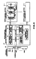
- a synchronization control system of a servo motor comprises servo motors 1 and servo control units 2 for n shafts and synchronously controls a combination of desired servo motors among these servo motors 1.
- a setting device 4 previously sets parameters for servo control individually for each of the n shafts and previously sets parameters for servo control for a synchronizing operation.
- Servo control conditions are programmed by this setting.
- Data which determines synchronization conditions of servo motors of respective shafts is applied, when required, by an input device 1 independently of setting by the settinhg device 4.
- the synchronization codition determining data includes, for example, data of combination of synchronized shafts and data of section for synchronization.
- a moving pattern preparation device 5 determines servo motor shafts to be synchronously controlled on the basis of the synchronization condition determining data applied through the input device 3 and prepares a moving pattern to a target position on the basis of the parameters for servo control with respect to each servo motor shaft to be synchronously controlled. Positioning command data corresponding to the prepared moving pattern is supplied to the servo control unit 2 corresponding to each shaft thereby to synchronously control the servo motor 1 corresponding to each shaft.
- synchronization conditions when the synchronization conditions have been changed on the basis of the synchronization condition determining data applied through the input device 3, a new moving patern corresponding to the changed synchronization conditions is prepared and servo control of the respective shafts is performed in accordance with the new moving pattern. Accordingly, the synchronization conditions can be changed at any desired moving position.
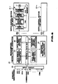
- servo control sections 10 - 1 to 10 - n for n shafts may be of a known construction which includes a servo motor 11 and a servo control unit.
- the servo control unit includes a sensor 12 for detecting a rotational position and a speed of rotation of the servo motor 11, a position control circuit 13 responsive to a command value x and position feedback data from the sensor 12 for providing control data v corresponding to deviation in position, a speed control circuit 14 responsive to this data v and speed feedback data from the sensor 12 for providing control data i corresponding to deviation in speed, and a current control circuit 15 for controlling drive current of the servo motor 11 in response to this data i.
- the command value x to each shaft is generated by a microcomputer 20 which is constructed to function as a moving pattern generation device.
- the command value x is provided by the microcomputer 20 as data x(t) (distinguished for each shaft by x1(t) to xn(t)) which indicates a moving position for unit time ⁇ t (i.e., absolute value of a moving position at each moment).
- the microcomputer 20 includes, as is well known, hardware circuits such as a central processing unit (CPU), a program memory and a working memory. In Fig. 2, however, illustration of these hardware circuits is omitted.
- Blocks designated as each shaft component speed calculation section 21, remaining distance calculation section 22 and remaining moving pattern calculation section are functional blocks showing a part of processing function of the microcomputer 20.
- Data memories 24 and 25 store various data relating to servo control.
- the first data memory 24 stores parameter data for determining servo control conditions and the second data memory 25 stores remainig moving pattern of each shaft calculated by the remaining moving pattern calculation section 23.
- the parameter data for determining servo control conditions stored in the first data memory 24 include, for example,
- These parameters may be programmed by a suitable method and then stored in the data memory 24.
- these parameters may be set and input with desired contents (i.e., programmed) by a setting and inputting means such as a keyboard and stored in the data memory 24.
- these parameters may be programmed with desired contents by an unillustrated separate program means and stored in the data memory 24 by an on-line or off-line data transfer.
- the first data memory 24 may either be a RAM or a ROM.
- An input circuit 26 is provided for receiving, when required, combination setting data CM1 to CMm for determining, with respect to m combinations, one or more shafts of the combinations and synchronization/non-synchronization command data SY1 to SYm from outside.
- these combination setting data CM1 o CMm and the synchronization/non-synchronization command data SY1 to SYm are not previously set (programmed) in the first data memory 24 as the other parameters for servo control but are applied, when required, from outside through the input circuit 26.
- the combination setting data CM1 to CMm respectively consist of an n-bit signal with each bit thereof corresponding to one of the n servo motors. A bit in the data corresponding to a servo motor shaft belonging to the particular combination becomes "1".
- the synchronization/non-synchronization command data SY1 to SYm respectively consist of a one-bit signal which becomes "1" with respect to a combination to which the synchronizing operation is given.
- combination setting data CM1 to CMm and the synchronization/non-synchronization command data SY1 to SYm may be set and input, when required, by suitable means such as an unillustrated switch or, alternatively, may be input on-line from a suitable exterior device such as a sequencer which is a host device.
- contents of the combination setting data CM1 to CMm supplied to the input circuit 26 and the synchronization/non-synchronization command data SY1 to SYm are constantly scanned and stored, and presence or absence of change in the contents is detected.
- FIG. 3 shows a processing concerning a single combination (the number of this combination is designated by k).
- a processing similar to the one shown in Fig. 3 is executed on a time shared basis or in parallel with respect to each of the m combinations.
- a necessary initial setting is executed. For example, an initial moving pattern of each shaft is obtained and stored in the second data memory 25.
- a moving pattern from a start position to a stop position is computed on the basis of the single shaft parameters which have been set in the first data memory 24 and this moving pattern is stored in the second data memory 25.
- the initial setting of course is not limited to this but a suitable combination of synchronization/non-synchronization may be set even in an initial period.
- the combination setting data CMk and the synchronization/non-synchronization command data SYk concerning the k-th combination are loaded from the input circuit 26 (step 30).
- step 31 whether the loaded synchronization/non-synchronization command data SYk is "1" or not, i.e., whether the synchronizing operation has been designated or not, is examined. If result of examination is NO, the computed moving pattern concerning the servo motor shaft belonging to the particular combination is referred to from the second data memory 25 on the basis of the combination setting data CMk and read out at one address unit (per unit time) (step 32).
- step 31 the routine proceeds to step 33 in which whether or not the synchronization/non-synchronization command data SYk in the preceding cycle was "1" is examined. If result of examination is NO, it will be meant that the operaton mode has changed from non-synchronization to synchronization and processing of steps 34 to 37 is executed. If result of examination is YES, it will be meant that the synchronized state continues and the routine proceeds to step 38.
- Step 38 is a similar processing to step 32.
- the computed moving pattern concerning the servo motor shaft belonging to the particular combination is referred to from the second data memory on the basis of the combination setting data CMk and read out at one address unit (per unit time).
- servo motor shafts which should be synchronously controlled are determined in accordance with the combination setting data CMk and, with respect to these shafts, a moving pattern to a target position (stop position) is prepared on the basis of the parameter data for servo control which have been set in the first data memory 24.
- step 34 remaing moving distance of the respective shafts belonging to the combination and resultant remaining moving distance of these shafts are calculated. More specifically, the remaining moving distance of the respective shafts and resultant remaining moving distance of these shafts are calculated in the following steps:
- the suffix "1" in the reference characters designating the above setting data is used for distinguishing the shaft number.
- the number of shaft about which the remaining moving distance is to be calculated is made 1 in this instance.
- the speed pattern of the single shaft is assumed to be one shown in Fig. 4. This speed pattern is determined by the above single shaft parameters Ta1, Td1 and Vc1.
- starting time of this data Ts is determined as follows depending upon whether the section at which the synchronization command has been given (i.e., the section in which the operation mode has been switched from non-synchronizatin to synchronization) is the acceleration section, constant speed section or the deceleration section: In the acceleration section, a time point at which moving starts. In the constant speed section, a time point at which acceleration ends. In the deceleration section, a time point at whcih deceleration starts.
- Remaining moving distance Lt1 of the particular shaft is calculated in the following manner by utilizing the single shaft parameters Ta1, Td1, Vc1 and Lt1 and the time variation data Ts depending upon whether the section in which the synchronization command has been given (the section in which the operation mode has been switched from non-synchronization to synchronization) is the acceleration section, costant speed section or deceleration section:
- Tc represents time elapsed in the constant speed section.
- the value of the time data Ts at the end of the constant speed section may be stored in a suitable manner as the time Tc.
- the above equations obtain the remainig moving distance Lt1′ by calculating the amount which the particular shaft has already moved by integration of the speed and subtracting this amount from the total predetermined amount of moving Lt1.
- step 35 component moving speed of each shaft of the combination is calculated. More particularly, the component moving speed is calculated by processing described below.
- the data memory 24 is referred to and resultant moving speed setting data VcS during synchronization among the synchronized shaft parameters of the particular combination is used.
- This resultant moving speed during synchronization represents a resultant constant moving speed when the respective shafts of the combination perform the synchronizing operation.
- the component moving speed VcS1 of each shaft of the combination is calculated by the following equation on the basis of the remaining moving distance Lt1′, the resultant moving distance LtS′ and the resultant moving speed setting data VcS calculated in the preceding step.
- step 36 the remaining moving pattern of each shaft of the combination is prepared on the basis of the remaining moving distance Lt1′ ?? and the component moving speed VcS1 Vietnamese . More specifically, the remaining moving pattern is prepared by a processing described below.
- the pattern consisting of solid lines and broken lines represent initial speed patterns of a single shaft in which the solid lines represent sections which have already moved.
- Chain-and-dot lines represent speed patterns corresponding to remaining moving patterns prepared by switching to the synchronization command.
- the moving pattern (remaining moving pattern) consisting of aggregation of moving position data x(t) for each unit time ⁇ t can be calculated by integration of the speed patterns.
- FIG. 5a A modified example of the pattern in this case is shown in Fig. 5a.
- the inclination of an acceleration section from speed 0 to component moving speed VcS1 of the particular shaft i.e., acceleration
- the inclination consists of a section from the current speed at a time point of switching to the synchronization command to the component moving speed VcS1.
- the pattern is prepared in such a manner that, in the constant speed section, the speed of the component moving speed VcS1 is maintained and, in the deceleration section, time from the component moving speed VcS1 to speed 0 of the particular shaft becomes the deceleration time setting data TdS during synchronization.
- the time point of switching from the constant speed section to the deceleration section is calculated properly so that integration of the entire speed pattern becomes the moving distance Lt1.
- the speed pattern shown by the chain-and-dot line in Fig. 5a and a remaining speed pattern based on this speed pattern are prepared and stored in the data memory 25.
- the speed pattern stored originally in the data memory 25 was the pattern shown by the solid line and the dotted line in Fig. 5a.
- the pattern has now been changed to one shown by the solid line and the chain-and-dot line in Fig. 5a.
- the section of the solid line in the pattern consisting of the solid line and the chain-and-dot line represents the finished moving pattern and the section of the chain-and-dot line represents the remaining moving pattern.
- a modified example of the pattern in this case is shown in Fig. 5b.
- a partial pattern which changes with a suitable transient characteristic to the component moving speed VcS1 is prepared so that the speed changes quickly and smoothly from the constant speed Vc1 to the component moving speed VcS1 of the particular shaft. Thereafter, the pattern maintains the component moving speed VcS1.
- the pattern is determined so that time from the component moving speed VcS1 of the particular shaft to the speed 0 becomes the time of the deceleration time setting data TdS during synchronization.
- the time point of switching from the constant speed section to the deceleration section is properly calculated so that integration of the entire speed pattern corresponds to the moving distance Lt1.
- the speed pattern shown by the chain-and-dot line in Fig. 5b and a remaining moving pattern based on this speed pattern are prepared and stored in the data memory 25.
- the moving pattern stored originally in the data memory 25 was the speed pattern shown by the solid line and the dotted line in Fig. 5b.
- the pattern has now been changed to the one shown in the solid line and the chain-and-dot line.
- the section of the solid line in the moving pattern consisting of the solid line and the chain-and-dot line represents the finished moving pattern and the section of the chain-and-dot line represents the remaining moving pattern.
- the inclination of the deceleration section (degree of deceleration) is determined so that time from the component moving speed VcS1 of the particular shaft to speed 0 becomes the time of the deceleration time setting data TdS during synchronization and a new pattern is set so that a section from the current speed at a time point of switching to the synchronization command to speed 0 becomes the inclination.
- the shape of the new pattern shown by the chain-and-dot line is adjusted suitably so that the area of the dotted line becomes equal to the area of the new pattern shown by the chain-and-dot line.
- the remaining moving pattern from the current point to the target point is calculated with respect to each shaft of the combination to which the synchronization command has been given.
- next step 37 the new moving pattern of each shaft which has been prepared in the preceding step is stored in the second data memory 25. In other words, the moving pattern stored in the data memory 25 is renewed.
- step 39 the moving position command value x(t) for each shaft of the combination is read from the data memory 25 and supplied to the servo control sections 10 - 1 to 10 - n corresponding to the respective shafts. Thereafter, the routine returns to processing of step 30 at a next scan timing.
- steps 30 to 39 is a processing for one combination and a processing similar to steps 30 to 39 is made on a time shared basis or in parallel with respect to m combinations.
- the moving pattern of each shaft which has been initially set by the initial processing is stored in the second data memory 25.
- the moving pattern prepared on the basis of the single shaft parameters is stored in the second data memory 25.
- the moving position data x(t) for each unit time ⁇ (t) is read in step 32 from the prepared moving pattern stored in the second data memory 25 and this data is supplied to a corresponding one of the servo control sections 10 - 1 to 10 - n as an absolute position command value of the unit time ⁇ (t).
- step 33 If it is confirmed in this step that the data SYk was "0" in the preceding scan cycle, processing of steps 34 to 37 is performed, that is, a new moving pattern, i.e., remaining moving pattern, based on the synchronized shaft parameters is prepared and contents of a corresponding moving pattern stored in the second data memory 25 are thereby renewed. Then, the moving position data x(t) for unit time ⁇ (t) corresponding to the new moving pattern for synchronizing operation is read out and supplied as a command value to a corresponding one of the servo control sections 10 - 1 to 10 - n.
- step 38 the renewed moving pattern for synchronizing operation is read from the second data memory 25 and the read out moving position data x(t) for unit time ⁇ (t) is supplied as a command value to a corresponding one of the servo control sections 10 - 1 to 10 - n.
- the moving pattern for synchronizing operation is directly used.
- a moving pattern may be prepared again on the basis of the single shaft parameters.
- the section of synchronizing operation can be determined as desired. Besides, change of this section of synchronizing operation can be made freely by changing the synchronization/non-synchronization command data SYk.
- the command value provided by the microcomputer 20 to each shaft is the absolute value x(t) of the moving position for unit time ⁇ t.
- the command value however is not limited to this but it may be a minute amount of movement ⁇ x.
- An embodiment utilizing this type of command value is shown in Fig. 6.
- an incremental pulse corresponding to a minute amount of movement ⁇ x for unit time ⁇ t (shown as ⁇ x1/ ⁇ t to ⁇ xn/ ⁇ t for each shaft) is provided as the command value by the microcomputer 20.
- the servo control sections 10 - 1 to 10 - n of the respective shafts include respectively a difference counter 16 for obtaining a difference between the command pulse train ⁇ x1/ ⁇ t to ⁇ xn/ ⁇ t provided by the microcomputer 20 and a position feedback pulse from s sensor 12 and the output of this difference counter 16 (position difference data) is applied to a speed control circuit 14 through a position loop gain control circuit 17.
- the sensor 12 generates an incremental pulse corresponding to the position whereas in the embodiment of Fig. 2, the sensor 12 generates absolute data of a detected position.
- the moving pattern is stored in the memory and, when the contents of the synchronization/non-synchronization command data SYk have been changed, the remaining moving pattern is made again and the contents of the moving pattern stored in the memory are renewed by this remaining moving pattern.
- the moving pattern may be made on real time base by always examining the contents of the synchronization/non-synchronization command data SYk.
- the process of preparation of the remaining moving pattern is not limited to the above described embodiments but may be suitably modified as desired.
- the speed change characteristics in the acceleration and deceleration sections are linear but they may be non-linear characteristics such as a logarithmic function or an exponential function.
- the moving pattern preparation means need not necessarily be a microcomputer but may be constructed of an exclusive hardware circuit.
- various parameter information such as combinations of servo motors and synchronized section used for synchronizing operation can be supplied not from a program but from outside on a real time base.
- Synchronization conditions can be changed at a desired moving position and, when the synchronization conditions have been changed, a new moving pattern can be prepared in accordance with the changed synchronization conditions. Accordingly, the synchronizaiton conditions can be changed at a desired moving position and therefore a novel and useful servo motor synchonization control system of a free date (free combination) or free rendezvous (free synchronous driving) type can be provided.
Landscapes
- Engineering & Computer Science (AREA)
- Human Computer Interaction (AREA)
- Manufacturing & Machinery (AREA)
- Physics & Mathematics (AREA)
- General Physics & Mathematics (AREA)
- Automation & Control Theory (AREA)
- Numerical Control (AREA)
- Control Of Position Or Direction (AREA)
- Control Of Multiple Motors (AREA)
Applications Claiming Priority (2)
| Application Number | Priority Date | Filing Date | Title |
|---|---|---|---|
| JP1216136A JP2824588B2 (ja) | 1989-08-24 | 1989-08-24 | サーボモータ同期制御方式 |
| JP216136/89 | 1989-08-24 |
Publications (3)
| Publication Number | Publication Date |
|---|---|
| EP0414046A2 true EP0414046A2 (de) | 1991-02-27 |
| EP0414046A3 EP0414046A3 (en) | 1991-07-03 |
| EP0414046B1 EP0414046B1 (de) | 1995-12-06 |
Family
ID=16683832
Family Applications (1)
| Application Number | Title | Priority Date | Filing Date |
|---|---|---|---|
| EP90115209A Expired - Lifetime EP0414046B1 (de) | 1989-08-24 | 1990-08-08 | Synchronisationsregelsystem für Servomotoren |
Country Status (4)
| Country | Link |
|---|---|
| US (1) | US5202611A (de) |
| EP (1) | EP0414046B1 (de) |
| JP (1) | JP2824588B2 (de) |
| DE (1) | DE69023982T2 (de) |
Cited By (3)
| Publication number | Priority date | Publication date | Assignee | Title |
|---|---|---|---|---|
| EP0531653A2 (de) * | 1991-09-13 | 1993-03-17 | Mitsubishi Denki Kabushiki Kaisha | Interaktiv programmierbare Einrichtung zur Positionierung und Steuerung unter Verwendung einer Anzeigeeinrichtung |
| EP0908804A2 (de) * | 1997-10-07 | 1999-04-14 | Fanuc Ltd | Bewegungssteuerung |
| CN111459200A (zh) * | 2020-03-27 | 2020-07-28 | 中信重工机械股份有限公司 | 一种袋装水泥自动装车机器人伺服控制系统 |
Families Citing this family (16)
| Publication number | Priority date | Publication date | Assignee | Title |
|---|---|---|---|---|
| JP3083870B2 (ja) * | 1991-05-10 | 2000-09-04 | ファナック株式会社 | 数値制御装置 |
| JP2897547B2 (ja) * | 1992-04-10 | 1999-05-31 | 三菱電機株式会社 | 被駆動機械の駆動制御装置、並びに、被駆動機械の駆動制御装置におけるパラメータ表示方法 |
| JP2862052B2 (ja) * | 1993-04-01 | 1999-02-24 | 三菱電機株式会社 | 位置指令方法及びその装置 |
| US5420485A (en) * | 1993-08-20 | 1995-05-30 | Forcam Inc. | Uncoordinated machine initialization system and method |
| DE59505810D1 (de) * | 1994-03-09 | 1999-06-10 | Rieter Ag Maschf | Bandablage |
| US5798626A (en) * | 1996-08-09 | 1998-08-25 | Emhart Glass Machinery Investments Inc. | Servo motor control |
| BE1013174A3 (nl) * | 1999-12-10 | 2001-10-02 | Picanol Nv | Werkwijze en aandrijfsysteem voor een machine. |
| DE60335966D1 (de) | 2002-10-31 | 2011-03-17 | Sumitomo Heavy Industries | Formmaschine und verfahren zur steuerung derselben |
| US7038421B2 (en) * | 2003-06-17 | 2006-05-02 | International Business Machines Corporation | Method and system for multiple servo motor control |
| US7271554B2 (en) * | 2003-07-30 | 2007-09-18 | Canon Kabushiki Kaisha | Motor-driving circuit and recording apparatus including the same |
| JP4003792B2 (ja) * | 2004-11-17 | 2007-11-07 | オムロン株式会社 | サーボモータ制御システム |
| US7180261B1 (en) * | 2006-03-17 | 2007-02-20 | Delta Electronics Inc. | Self-synchronous AC servo system for high-speed serial communication |
| WO2011030402A1 (ja) * | 2009-09-09 | 2011-03-17 | 三菱電機株式会社 | エレベータの制御装置 |
| JP5873140B2 (ja) * | 2014-06-25 | 2016-03-01 | ファナック株式会社 | 同期制御装置 |
| CN106502161B (zh) * | 2016-11-11 | 2023-10-27 | 北京精密机电控制设备研究所 | 三通道流量调节控制方法、装置及伺服控制驱动系统 |
| JP2022139198A (ja) * | 2021-03-11 | 2022-09-26 | オムロン株式会社 | 複数の移動機構を制御するシステムおよび方法 |
Citations (4)
| Publication number | Priority date | Publication date | Assignee | Title |
|---|---|---|---|---|
| US3909600A (en) * | 1972-06-26 | 1975-09-30 | Cincinnati Milacron Inc | Method and apparatus for controlling an automation along a predetermined path |
| US3952238A (en) * | 1973-11-29 | 1976-04-20 | Hymie Cutler | Programmable positioning apparatus and acceleration control system particularly useful therein |
| DE3005139A1 (de) * | 1980-02-12 | 1981-08-20 | Jungheinrich Unternehmensverwaltung Kg, 2000 Hamburg | Verfahren fuer eine optimale positioniergeschwindigkeit von numerisch gesteuerten achsen von handhabungsgeraeten und anordnung zur durchfuehrung des verfahrens |
| FR2561008A1 (fr) * | 1984-03-06 | 1985-09-13 | Textima Veb K | Procede pour la regulation de n mouvements d'entrainement montes en parallele |
Family Cites Families (6)
| Publication number | Priority date | Publication date | Assignee | Title |
|---|---|---|---|---|
| DE2827340C2 (de) * | 1978-06-22 | 1983-08-04 | Keiper Automobiltechnik Gmbh & Co Kg, 5630 Remscheid | Antriebseinrichtung mit wenigstens zwei Elektromotoren |
| US4376913A (en) * | 1981-01-16 | 1983-03-15 | Horix Manufacturing Co. | Method and apparatus for synchronously driving AC synchronous motors |
| US4565950A (en) * | 1982-11-09 | 1986-01-21 | Ricoh Company, Ltd. | Servo system |
| JPS6249503A (ja) * | 1985-08-29 | 1987-03-04 | Mitsubishi Electric Corp | 数値制御装置 |
| US4815013A (en) * | 1987-07-30 | 1989-03-21 | Universal Recording Corporation | Variable speed film transport interlock system and method using same |
| JPH0649260B2 (ja) * | 1989-02-28 | 1994-06-29 | 豊田工機株式会社 | 同期制御装置 |
-
1989
- 1989-08-24 JP JP1216136A patent/JP2824588B2/ja not_active Expired - Lifetime
-
1990
- 1990-08-08 EP EP90115209A patent/EP0414046B1/de not_active Expired - Lifetime
- 1990-08-08 DE DE69023982T patent/DE69023982T2/de not_active Expired - Fee Related
- 1990-08-09 US US07/565,268 patent/US5202611A/en not_active Expired - Fee Related
Patent Citations (4)
| Publication number | Priority date | Publication date | Assignee | Title |
|---|---|---|---|---|
| US3909600A (en) * | 1972-06-26 | 1975-09-30 | Cincinnati Milacron Inc | Method and apparatus for controlling an automation along a predetermined path |
| US3952238A (en) * | 1973-11-29 | 1976-04-20 | Hymie Cutler | Programmable positioning apparatus and acceleration control system particularly useful therein |
| DE3005139A1 (de) * | 1980-02-12 | 1981-08-20 | Jungheinrich Unternehmensverwaltung Kg, 2000 Hamburg | Verfahren fuer eine optimale positioniergeschwindigkeit von numerisch gesteuerten achsen von handhabungsgeraeten und anordnung zur durchfuehrung des verfahrens |
| FR2561008A1 (fr) * | 1984-03-06 | 1985-09-13 | Textima Veb K | Procede pour la regulation de n mouvements d'entrainement montes en parallele |
Cited By (8)
| Publication number | Priority date | Publication date | Assignee | Title |
|---|---|---|---|---|
| EP0531653A2 (de) * | 1991-09-13 | 1993-03-17 | Mitsubishi Denki Kabushiki Kaisha | Interaktiv programmierbare Einrichtung zur Positionierung und Steuerung unter Verwendung einer Anzeigeeinrichtung |
| US5715429A (en) * | 1991-09-13 | 1998-02-03 | Mitsubishi Denki Kabushiki Kaisha | Positioning and control apparatus that is interactively programmable using a display |
| US5859515A (en) * | 1991-09-13 | 1999-01-12 | Mitsubishi Denki Kabushiki Kaisha | Method of operating a virtual mechanical module which simulates a mechanical device |
| EP0531653B1 (de) * | 1991-09-13 | 1999-04-21 | Mitsubishi Denki Kabushiki Kaisha | Interaktiv programmierbare Einrichtung zur Positionierung und Steuerung unter Verwendung einer Anzeigeeinrichtung |
| EP0908804A2 (de) * | 1997-10-07 | 1999-04-14 | Fanuc Ltd | Bewegungssteuerung |
| EP0908804A3 (de) * | 1997-10-07 | 2000-11-15 | Fanuc Ltd | Bewegungssteuerung |
| CN111459200A (zh) * | 2020-03-27 | 2020-07-28 | 中信重工机械股份有限公司 | 一种袋装水泥自动装车机器人伺服控制系统 |
| CN111459200B (zh) * | 2020-03-27 | 2021-10-22 | 中信重工机械股份有限公司 | 一种袋装水泥自动装车机器人伺服控制系统 |
Also Published As
| Publication number | Publication date |
|---|---|
| EP0414046B1 (de) | 1995-12-06 |
| JPH0382390A (ja) | 1991-04-08 |
| DE69023982T2 (de) | 1996-06-27 |
| EP0414046A3 (en) | 1991-07-03 |
| JP2824588B2 (ja) | 1998-11-11 |
| US5202611A (en) | 1993-04-13 |
| DE69023982D1 (de) | 1996-01-18 |
Similar Documents
| Publication | Publication Date | Title |
|---|---|---|
| EP0414046B1 (de) | Synchronisationsregelsystem für Servomotoren | |
| EP1090722B1 (de) | Steuerungssystem zum synchronen kooperativen Betreiben einer Mehrzahl von Robotern | |
| US4692856A (en) | Position control of multiple tools based on elapsed time of tool operation | |
| US4409650A (en) | Automatic position controlling apparatus | |
| US4348731A (en) | Automatic working apparatus and method of controlling the same | |
| US4456863A (en) | Apparatus for automatic calibration of servo response | |
| EP0080375B1 (de) | Verfahren und Gerät zum Messen der Ist-Position in einem Positionierungssystem | |
| EP0528047B1 (de) | Verfahren zur steuerung des dichtungsmasse-stromes für einen dichtungsmasse austragenden industrieroboter | |
| US5101146A (en) | Device for correcting mechanical errors in nc machine | |
| CN100461053C (zh) | 数字控制器 | |
| US4803640A (en) | Control arrangement for an industrial robot | |
| US4888536A (en) | Device for controlling positioning of an object | |
| US5371452A (en) | Adjustable time constant control and method system for a servomotor | |
| JPH0736514A (ja) | 3次元工具径補正方式 | |
| US4504772A (en) | Method of sensing current position in position control system | |
| EP0505569B1 (de) | Verfahren zur Anzeigedes Belastungszustands | |
| US5337249A (en) | Numerical control machining animation with workpiece and tool movement | |
| EP0312716B1 (de) | Verfahren zum Aufnehmen und Wiedergeben von Steuerdaten in einem Roboter | |
| US4415967A (en) | Multi-axis controller | |
| US6999844B2 (en) | Numerical controller | |
| US4988937A (en) | Synchronous control system and method therefor | |
| US4701686A (en) | Line tracking control method | |
| JPH0615547A (ja) | 工作機械における1本もしくは1本以上の軸線を制御する方法ならびに装置 | |
| JPH10301614A (ja) | 数値制御装置 | |
| EP0646852A1 (de) | Regelungssystem für die beschleunigung/verzögerung einer numerischen steuerung |
Legal Events
| Date | Code | Title | Description |
|---|---|---|---|
| PUAI | Public reference made under article 153(3) epc to a published international application that has entered the european phase |
Free format text: ORIGINAL CODE: 0009012 |
|
| 17P | Request for examination filed |
Effective date: 19901207 |
|
| AK | Designated contracting states |
Kind code of ref document: A2 Designated state(s): DE FR GB IT SE |
|
| PUAL | Search report despatched |
Free format text: ORIGINAL CODE: 0009013 |
|
| AK | Designated contracting states |
Kind code of ref document: A3 Designated state(s): DE FR GB IT SE |
|
| 17Q | First examination report despatched |
Effective date: 19940201 |
|
| GRAA | (expected) grant |
Free format text: ORIGINAL CODE: 0009210 |
|
| AK | Designated contracting states |
Kind code of ref document: B1 Designated state(s): DE FR GB IT SE |
|
| PG25 | Lapsed in a contracting state [announced via postgrant information from national office to epo] |
Ref country code: IT Free format text: LAPSE BECAUSE OF FAILURE TO SUBMIT A TRANSLATION OF THE DESCRIPTION OR TO PAY THE FEE WITHIN THE PRE;WARNING: LAPSES OF ITALIAN PATENTS WITH EFFECTIVE DATE BEFORE 2007 MAY HAVE OCCURRED AT ANY TIME BEFORE 2007. THE CORRECT EFFECTIVE DATE MAY BE DIFFERENT FROM THE ONE RECORDED.SCRIBED TIME-LIMIT Effective date: 19951206 Ref country code: FR Effective date: 19951206 |
|
| REF | Corresponds to: |
Ref document number: 69023982 Country of ref document: DE Date of ref document: 19960118 |
|
| PG25 | Lapsed in a contracting state [announced via postgrant information from national office to epo] |
Ref country code: SE Effective date: 19960306 |
|
| EN | Fr: translation not filed | ||
| PG25 | Lapsed in a contracting state [announced via postgrant information from national office to epo] |
Ref country code: GB Effective date: 19960808 |
|
| PLBE | No opposition filed within time limit |
Free format text: ORIGINAL CODE: 0009261 |
|
| STAA | Information on the status of an ep patent application or granted ep patent |
Free format text: STATUS: NO OPPOSITION FILED WITHIN TIME LIMIT |
|
| 26N | No opposition filed | ||
| GBPC | Gb: european patent ceased through non-payment of renewal fee |
Effective date: 19960808 |
|
| PGFP | Annual fee paid to national office [announced via postgrant information from national office to epo] |
Ref country code: DE Payment date: 19990921 Year of fee payment: 10 |
|
| PG25 | Lapsed in a contracting state [announced via postgrant information from national office to epo] |
Ref country code: DE Free format text: LAPSE BECAUSE OF NON-PAYMENT OF DUE FEES Effective date: 20010501 |