EP0413143B1 - Rasierapparatekopf, insbesondere Rasierklingeneinheit eines Nassrasierapparates - Google Patents
Rasierapparatekopf, insbesondere Rasierklingeneinheit eines Nassrasierapparates Download PDFInfo
- Publication number
- EP0413143B1 EP0413143B1 EP90113460A EP90113460A EP0413143B1 EP 0413143 B1 EP0413143 B1 EP 0413143B1 EP 90113460 A EP90113460 A EP 90113460A EP 90113460 A EP90113460 A EP 90113460A EP 0413143 B1 EP0413143 B1 EP 0413143B1
- Authority
- EP
- European Patent Office
- Prior art keywords
- plastic housing
- razor
- blade
- head according
- razor head
- Prior art date
- Legal status (The legal status is an assumption and is not a legal conclusion. Google has not performed a legal analysis and makes no representation as to the accuracy of the status listed.)
- Expired - Lifetime
Links
- 125000006850 spacer group Chemical group 0.000 claims abstract description 54
- 238000003780 insertion Methods 0.000 claims abstract description 10
- 230000037431 insertion Effects 0.000 claims abstract description 10
- 238000005520 cutting process Methods 0.000 claims description 11
- 239000011248 coating agent Substances 0.000 claims description 3
- 238000000576 coating method Methods 0.000 claims description 3
- 229920000642 polymer Polymers 0.000 claims description 3
- 230000001681 protective effect Effects 0.000 claims 2
- 239000004922 lacquer Substances 0.000 claims 1
- 238000011161 development Methods 0.000 description 10
- 230000018109 developmental process Effects 0.000 description 10
- 238000005452 bending Methods 0.000 description 4
- 238000004140 cleaning Methods 0.000 description 4
- 238000003466 welding Methods 0.000 description 4
- 238000004026 adhesive bonding Methods 0.000 description 3
- 239000000463 material Substances 0.000 description 3
- 239000006260 foam Substances 0.000 description 2
- 238000004519 manufacturing process Methods 0.000 description 2
- 239000002184 metal Substances 0.000 description 2
- 229920002120 photoresistant polymer Polymers 0.000 description 2
- 230000000284 resting effect Effects 0.000 description 2
- 230000000694 effects Effects 0.000 description 1
- 230000001771 impaired effect Effects 0.000 description 1
- 238000000034 method Methods 0.000 description 1
- 238000010137 moulding (plastic) Methods 0.000 description 1
- 238000003825 pressing Methods 0.000 description 1
- 238000005476 soldering Methods 0.000 description 1
- 230000003313 weakening effect Effects 0.000 description 1
Images





Classifications
-
- B—PERFORMING OPERATIONS; TRANSPORTING
- B26—HAND CUTTING TOOLS; CUTTING; SEVERING
- B26B—HAND-HELD CUTTING TOOLS NOT OTHERWISE PROVIDED FOR
- B26B21/00—Razors of the open or knife type; Safety razors or other shaving implements of the planing type; Hair-trimming devices involving a razor-blade; Equipment therefor
- B26B21/08—Razors of the open or knife type; Safety razors or other shaving implements of the planing type; Hair-trimming devices involving a razor-blade; Equipment therefor involving changeable blades
- B26B21/14—Safety razors with one or more blades arranged transversely to the handle
- B26B21/22—Safety razors with one or more blades arranged transversely to the handle involving several blades to be used simultaneously
- B26B21/222—Safety razors with one or more blades arranged transversely to the handle involving several blades to be used simultaneously with the blades moulded into, or attached to, a changeable unit
-
- B—PERFORMING OPERATIONS; TRANSPORTING
- B29—WORKING OF PLASTICS; WORKING OF SUBSTANCES IN A PLASTIC STATE IN GENERAL
- B29C—SHAPING OR JOINING OF PLASTICS; SHAPING OF MATERIAL IN A PLASTIC STATE, NOT OTHERWISE PROVIDED FOR; AFTER-TREATMENT OF THE SHAPED PRODUCTS, e.g. REPAIRING
- B29C65/00—Joining or sealing of preformed parts, e.g. welding of plastics materials; Apparatus therefor
- B29C65/02—Joining or sealing of preformed parts, e.g. welding of plastics materials; Apparatus therefor by heating, with or without pressure
- B29C65/06—Joining or sealing of preformed parts, e.g. welding of plastics materials; Apparatus therefor by heating, with or without pressure using friction, e.g. spin welding
-
- B—PERFORMING OPERATIONS; TRANSPORTING
- B29—WORKING OF PLASTICS; WORKING OF SUBSTANCES IN A PLASTIC STATE IN GENERAL
- B29C—SHAPING OR JOINING OF PLASTICS; SHAPING OF MATERIAL IN A PLASTIC STATE, NOT OTHERWISE PROVIDED FOR; AFTER-TREATMENT OF THE SHAPED PRODUCTS, e.g. REPAIRING
- B29C65/00—Joining or sealing of preformed parts, e.g. welding of plastics materials; Apparatus therefor
- B29C65/02—Joining or sealing of preformed parts, e.g. welding of plastics materials; Apparatus therefor by heating, with or without pressure
- B29C65/08—Joining or sealing of preformed parts, e.g. welding of plastics materials; Apparatus therefor by heating, with or without pressure using ultrasonic vibrations
-
- B—PERFORMING OPERATIONS; TRANSPORTING
- B29—WORKING OF PLASTICS; WORKING OF SUBSTANCES IN A PLASTIC STATE IN GENERAL
- B29C—SHAPING OR JOINING OF PLASTICS; SHAPING OF MATERIAL IN A PLASTIC STATE, NOT OTHERWISE PROVIDED FOR; AFTER-TREATMENT OF THE SHAPED PRODUCTS, e.g. REPAIRING
- B29C65/00—Joining or sealing of preformed parts, e.g. welding of plastics materials; Apparatus therefor
- B29C65/48—Joining or sealing of preformed parts, e.g. welding of plastics materials; Apparatus therefor using adhesives, i.e. using supplementary joining material; solvent bonding
-
- B—PERFORMING OPERATIONS; TRANSPORTING
- B29—WORKING OF PLASTICS; WORKING OF SUBSTANCES IN A PLASTIC STATE IN GENERAL
- B29C—SHAPING OR JOINING OF PLASTICS; SHAPING OF MATERIAL IN A PLASTIC STATE, NOT OTHERWISE PROVIDED FOR; AFTER-TREATMENT OF THE SHAPED PRODUCTS, e.g. REPAIRING
- B29C66/00—General aspects of processes or apparatus for joining preformed parts
- B29C66/50—General aspects of joining tubular articles; General aspects of joining long products, i.e. bars or profiled elements; General aspects of joining single elements to tubular articles, hollow articles or bars; General aspects of joining several hollow-preforms to form hollow or tubular articles
- B29C66/51—Joining tubular articles, profiled elements or bars; Joining single elements to tubular articles, hollow articles or bars; Joining several hollow-preforms to form hollow or tubular articles
- B29C66/54—Joining several hollow-preforms, e.g. half-shells, to form hollow articles, e.g. for making balls, containers; Joining several hollow-preforms, e.g. half-cylinders, to form tubular articles
-
- B—PERFORMING OPERATIONS; TRANSPORTING
- B29—WORKING OF PLASTICS; WORKING OF SUBSTANCES IN A PLASTIC STATE IN GENERAL
- B29L—INDEXING SCHEME ASSOCIATED WITH SUBCLASS B29C, RELATING TO PARTICULAR ARTICLES
- B29L2031/00—Other particular articles
- B29L2031/718—Cosmetic equipment, e.g. hair dressing, shaving equipment
- B29L2031/7186—Shaving equipment
Definitions
- the invention relates to a razor head arranged at the front end of a handle, in particular a razor blade unit of a wet razor, with a plastic housing having a front guide bar and a blade platform on a front edge and with a blade block in which a single or double razor blade is permanently attached to a spacer.
- the blade block seen essentially from the front edge, can be inserted from above into the plastic housing on the blade platform and can be fixed in the plastic housing after insertion.
- a single or double razor blade is embedded in the shaver head in a plastic housing. If the razor head is designed separately and can be attached to a handle, for which purpose the handle and the razor head have interlocking devices that correspond to one another, this is referred to as a so-called razor blade unit.
- a razor head in the form of a razor blade unit of the type specified at the outset is known from GB-PS 2 087 287.
- the razor blade unit has a one-piece plastic housing in which either a single or a double razor blade is permanently attached and rests on a blade platform of the plastic housing.
- a double razor blade is between the two razor blades a spacer is arranged, wherein the two razor blades are only applied to the spacer and are not firmly connected to it. This has the disadvantage that the razor blades flutter during the shaving process and thus impair the shaving properties of the razor.
- this has molded fingers extending towards the front, which at the same time form a cover and, together with the front guide bar of the razor blade unit, define the razor geometry.
- the package of the razor blades and the spacer is pushed from the front between the blade platform and the upper fingers, the latter pressing from above onto the razor blades and the spacer and thus fixing them within the plastic housing.
- projections are provided in the side walls of the plastic housing, into which lateral recesses of the spacer snap when they are pushed in.
- the single razor blade is fastened inside the plastic housing in accordance with the double razor blade, in that the razor blade is clamped between the upper fingers and the lower blade platform.
- GB-A-2 166 997 discloses a shaver head of a wet shaver arranged at the front end of a handle.
- the razor head has a plastic housing with a front guide bar and with a blade platform.
- a blade block is provided as a separate component for the razor blade in the form of a single or double razor blade, in which the single or double razor blade is permanently attached to a spacer, for example by riveting.
- This blade block is inserted essentially from above into the plastic housing on its blade platform and is then permanently fixed by inserting a cover cap between it and the blade platform of the plastic housing.
- a disadvantage of this known razor head is the design of the blade block and its arrangement within the plastic housing. Since the spacer for the razor blades is flat, it is not very stable and can bend very easily. However, a curved razor blade does not lead to an optimal shaving result and optimal shaving comfort. In addition, openings are to be provided in the spacer and in the razor blades for fixing the blade block within the plastic housing, which openings are plugged onto corresponding pins on the blade platform of the plastic housing. This means not only a weakening of the razor blades, but it is also not possible to optimally fix the blade block within the plastic housing, since it lacks the required stability.
- a plastic housing has a front guide bar and a blade platform.
- the razor blades in the form of a double razor blade are arranged in a block of blades.
- This consists of an essentially W-shaped folded spacer, between the legs of which the two razor blades are clamped and with the top leg defining a cover cap.
- the blade block designed in this way in the plastic housing it is placed on the blade platform from above and the laterally projecting extensions of the spacer are bent downwards such that they grip around the plastic housing laterally.
- the blade block is essentially flat and therefore not very stable, particularly with regard to bending.
- the bending of the lateral extensions of the spacer does not ensure a very secure attachment of the blade block in the plastic housing, since changes in position can occur very easily during shaving. However, this has a disadvantageous effect on the shaving result and the shaving comfort.
- DE-A1-24 47 087 discloses a razor head in the form of a so-called razor blade unit of a wet shaver.
- the razor blade unit initially consists of a plastic housing with a front guide bar and a blade platform.
- a blade block in which two razor blades are permanently attached to a spacer under tension, is placed on the blade platform of the plastic housing from above.
- the fixation takes place by means of a cover cap, which has underneath pins for riveting both through the blade block and through the plastic housing. Again, the stability of the blade block is poor.
- DE-A1-27 50 796 also discloses a razor head in the form of a razor blade unit for a wet razor.
- a plastic housing is provided with a front guide bar and with a blade platform formed by stepped webs.
- a blade block has strips that are stepped in accordance with the webs and on which narrow razor blades are permanently attached either by soldering or clamping. The blade block thus formed is placed obliquely from above on the blade platform of the plastic housing and clamped in this. Again, the stability of the blade block is not sufficient.
- the object of the invention is to further develop the known razor head of a wet shaver in such a way that the design of the blade block and its arrangement in the plastic housing are improved.
- the invention proposes that a strip with an essentially L-shaped cross-sectional profile is provided for the blade block, one leg of which defines the spacer and the other leg of which is received by a corresponding longitudinal slot in the lower part of the plastic housing.
- a razor head of a wet shaver designed according to this technical teaching has the advantage that, on the one hand, the design of the blade block and, on the other hand, the arrangement of this blade block within the plastic housing is improved. Due to the L-shaped cross-sectional profile for the bar defining the spacer, an extremely stable blade block is created on the one hand for the pre-assembly and on the other hand for the arrangement within the plastic housing. Due to the L-profile, the spacer and therefore the razor blades arranged on the spacer are always flat, although the spacer can have openings for better cleaning of the shaver head.
- the blade block with the vertical leg of the L-profile is received in a corresponding longitudinal slot in the lower part of the plastic housing, a very secure fixation within the plastic housing is ensured in this way, without the blade block and thus the spacer with the razor blades being cut out and punched out must have for fixation.
- Another advantage of the angled spacer is that razor blades with narrow blades can be used.
- the razor blade (s) In a preferred attachment of the razor blade (s) to the spacer, these are (are) welded or glued to the spacer. This welding or gluing is preferably carried out over the entire contact area between the razor blade (s) on the spacer. This creates an optimal, large-area connection.
- the spacer is made of metal, while when gluing it can also be made of plastic.
- the two legs of the L-shaped bar are preferably perpendicular to one another.
- this is formed by short strip pieces which are rigidly connected to one another by webs in the region of those legs which are received by the longitudinal slot in the lower part of the plastic housing, and in the direction perpendicular to the cutting edge (s) Razor blade (s) aligned with the openings left between the last pieces, the back of the plastic housing is correspondingly open.
- the short strips are integrally formed with the webs located between them, so that you get a one-piece and stable by the bend bar, one leg of this bar forms the spacer for the razor blades with a double razor blade, the two razor blades on both sides of the spacer are arranged so that it is fixed between the two razor blades.
- openings are left above the webs in the region of those legs which are connected to one another by the webs. This increases the passage cross-section in that, in the case of a double razor blade, the bar has openings both between the razor blades and below the lower razor blade.
- the strip pieces are preferably connected to one another essentially in the central region of the legs, the lower part of the plastic housing having cutouts for receiving the free ends of the legs connected to one another by the webs.
- this results in an optimal cross-section on the other hand, the blade block can be stored in a simple and safe manner within the lower part of the plastic housing, these recesses defining the longitudinal slot for receiving one leg of the blade block.
- this is formed by support webs which extend perpendicular to the cutting edge (s) of the razor blade (s). These support webs are preferably in front of the short strip pieces of the strip of the blade block. In this way, only little material is required for the lower part of the plastic housing, since the blade block is not continuously supported by the blade platform over its entire length.
- the lower part of the plastic housing has openings between the support webs.
- the guide strip is chamfered from the top to the rear towards the rear.
- the support webs in the area behind the guide bar have cutouts on the top.
- the guide strip is formed in one piece with the lower part of the plastic housing.
- the blade block can be inserted into a lower part of the plastic housing having the blade platform on the blade platform and that a fixing strip defining a cover cap can be placed on the lower part of the plastic housing with intermediate arrangement and fixing of the blade block and is permanently connected to the lower part of the plastic housing.
- the razor head thus consists of three simple parts, namely the lower part, an upper part in the form of the fixing bar and the blade block. These three parts are easy to assemble by first plugging the blade block onto the lower part from above. The blade block is then finally fixed by attaching the upper fixing bar by permanently connecting it to the lower part of the plastic housing. This can all be carried out quickly and easily, and above all an exact positioning of the blade block and thus the razor blades within the plastic housing is guaranteed.
- the upper fixing strip In a development of the upper fixing strip, it has lateral wings, by means of which the fixing strip is fastened on a side wall of the lower part of the plastic housing. This creates a very stable connection between the upper fixing bar and the lower part of the plastic housing. The connection in this lateral area of the plastic housing can also be accomplished in a technically simple manner.
- the fixing bar can be a have rear wall, by means of which the fixing strip is attached to a rear wall of the lower part of the plastic housing. A technically simple connection between the upper fixing bar and the lower part of the plastic housing is also created.
- these two parts can be glued, welded, in particular ultrasonically welded, or inserted into one another.
- they can have corresponding pins and recesses which are in frictional engagement with one another when inserted into one another.
- the fixing strip defining the covering cap is preferably coated with a friction-reducing coating, in particular made of photoresist or a polymer.
- the fixing strip preferably has a rear wall which has openings which are aligned with the openings formed in the strip.
- the plastic housing is plastically deformable after the insertion of the blade block that the blade block is fixed between the deformed area and the blade platform.
- the razor head consists of only two parts, namely the plastic housing and the blade block. After inserting the blade block into the plastic case the blade block is finally fixed by a suitable plastic deformation of the plastic housing, so that the blade block is securely fixed in its position.
- fixation in the form of a plastic deformation can be carried out in a technically simple manner.
- the plastic housing is cold-formable in a further development.
- a development of the blade block suggests that the spacer protrudes beyond the ends of the razor blade (s) and the blade block is fixed in the area of these free ends of the spacer. This has the advantage that the blade block can be attached outside the effective range of the cutting edges of the razor blades, so that the shaving properties of the razor head are not impaired.
- an upwardly open recess is provided in each of the two side walls of the plastic housing, into which the ends of the blade block can be inserted from above, and in the region of these recesses the side walls are over the ends of the blade block for fixing them within the plastic housing bent inside.
- the recesses are preferably funnel-shaped.
- an essentially vertically upwardly extending strip is formed on the rear longitudinal side of the plastic housing.
- This bar takes on the function of the cover caps in the known razor heads and, together with the front guide bar and the razor blades, defines the shaving geometry.
- an essentially vertically upwardly extending strip is formed on the rear longitudinal side of the plastic housing, which strip is used to fix the blade block within the plastic housing either over the entire length or in partial areas is bent forward.
- an upwardly open recess is preferably provided in each of the two side walls of the plastic housing, into which the ends of the blade block can be inserted from above before the rear bar is bent forward. In this way, the blade block is very securely fixed in position within the plastic housing. The final fixation is then done by pre-bending the rear bar, which can be done over the entire length of this bar.
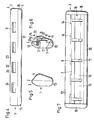
- FIGS. 1 to 9 A first embodiment and a second embodiment of a razor blade unit are shown in FIGS. 1 to 9.
- the razor blade unit 1 consists of a plastic housing 2. This is composed of a lower part 3 and an upper fixing strip 4, which are non-detachably connected to one another and immovably fix a blade block 6 carrying razor blades 5,5 '.
- the fixing strip 4 can be glued to the lower part 3, welded, in particular ultrasonically welded or connected to one another by means of pins / bores via frictional engagement.
- the lower part 3 of the plastic housing 2 initially has a central central web 7 which extends in the longitudinal direction.
- these support webs 8 carry a guide bar 10, which is rounded off with its front surface.
- the support webs 8 each have recesses 11 in the area behind the guide bar 10. Openings 12 are defined in the areas between adjacent support webs 8 and between the central web 7 and the guide bar 10, as can be seen in particular in the top view according to FIG. 7. This can also be seen from the bottom view in FIG. 2 of the entire razor blade unit 1.
- the support webs 8 of the lower part 3 of the plastic housing 2 form a blade platform 16 for supporting the blade block 6.
- This consists of a bar 17 which has an essentially L-shaped cross-sectional profile.
- the bar 17 consists of individual, short bar pieces 17 '. These are connected to one another by webs 18, specifically in the region of one leg 19 of the strip 17 or the leg 19 'of the strip pieces 17'.
- the webs 18 are integrally formed with the last pieces 17 'and sit essentially in the central region of the legs 19' of the last pieces 17 ', so that in each case an opening 20 is left above the webs 18, while the legs 19' have a free end .
- the other leg 19a of the bar 17 or the legs 19a 'of the bar pieces 17' serve to receive and fasten the two razor blades 5,5 '.
- the upper razor blade 5 is fastened on one side of the leg 19a and the lower razor blade 5 'on the opposite side of the leg 19a, so that it performs the function of a spacer 21.
- the two razor blades 5, 5 ' are aligned parallel to each other, while the cutting edges 9,9' are offset from one another.
- openings 20 are left between the legs 19a '.
- the blade block 6 thus formed is placed on the lower part 3 from above such that the underside of the lower razor blade 5 'comes to rest on the blade platform 16 defined by the support webs 8. Furthermore, the free ends of the legs 19 'of the strip pieces 17 come in the corresponding longitudinal slots 14 in the lower part 3 for receiving. The blade block 6 is thus fixed on or in the lower part 3 of the plastic housing 2.
- the fixing bar 4 is used to fix the blade block 6. This defines a cover cap 22 resting on the upper side of the upper razor blade 5. A rear wall 23 is formed thereon. This has openings 24 which are aligned with the openings 20 formed in the strip 17. Laterally, the fixing strip 4 then also has molded-on wings 25.
- the fixing strip 4 is pushed onto the lower part 3 from above.
- the rear wall 23 of the fixing strip 4 comes to lie flat on the rear wall 13 of the lower part 3 and the underside of the wings 25 of the fixing strip 4 on the side walls 15 of the lower part 5.
- the non-detachable connection between the fixing strip 4 and the lower part 3 can then be made by gluing, welding, in particular ultrasonic welding or by friction.
- the cover cap 22 defined by the fixing strip 4 can additionally be provided with a friction-reducing coating, for example made from photoresist or from a polymer.
- the angled bar 17 for the spacer 21 with the openings 20 for through-flow channels allows the production of a blade with narrow cutting edges.
- the openings 20 together with the openings 24 in the fixing strip and the openings 12 in the lower part 3 ensure a better flow as well improved and easier cleaning.
- the shape of the strip 17 is chosen such that overall no greater material consumption occurs than with non-angled spacers. This is essentially achieved in that the bar 17 is in the form of interlocking rakes.
- the particular advantage of this design is that despite the openings 20 between the razor blades 5.5 ', the bar 17 and thus the spacer 21 forms a stable unit with the razor blades 5.5' due to the angled shape.
- the additional blade cover in the form of a cover cap 22, which is formed by the fixing strip 4, is advantageous in the razor blade unit according to the invention.
- the razor blade unit 1 consists of a plastic housing 2. This has a front guide bar 10, two side walls 15, on the rear longitudinal side 28 parallel to the guide bar 10, a bar 29 extending vertically upwards and inside a blade platform 16. All of these parts are integrally formed with one another and thus form a plastic molding. On the underside of the plastic housing 2, this additionally has a locking mechanism 30, by means of which a handle, not shown, can be attached to form the finished shaving apparatus.
- two razor blades 5.5 ' are permanently attached.
- the two razor blades 5.5 'on a flat, elongated, cuboid spacer 21 are so permanently attached that the spacer 21 is sandwiched between the two razor blades 5.5'.
- the razor blade 5.5 'and the spacer 21 thus form a so-called blade block 6.
- the spacer 21 is slightly longer than the two razor blades 5.5 ', so that the spacer 21 protrudes somewhat over the ends of the razor blades 5.5'. These protruding, free ends of the spacer 21 serve to fix the blade block 6 within the plastic housing 2.
- the latter is provided in the region of the side walls 15 with a recess 26 which tapers in the direction of insertion .
- a rib 27 extending in the insertion direction is formed on the back of each recess 26.
- the blade block 6 is first inserted into the plastic housing 2 from above such that the free, projecting ends of the spacer 21 come to lie within the two recesses 26 in the side walls 15.
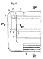
- the ribs 27 press the spacer 21 forward within the recesses 26 so that it comes to rest on the front side 31 of the recess 26, as can be seen in FIG. 14.
- the shaving geometry is reproducibly achieved, which is defined by the guide bar 10 and the cutting edges of the razor blades 5,5 'and finally by the upper edge of the bar 29.
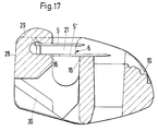
- FIG. 17 shows an alternative embodiment of the attachment of the blade block 6 within the plastic housing 2, specifically in a sectional illustration similar to that in FIG. 16.
- This embodiment can also have recesses 26 in the region of the side walls 15 of the plastic housing 2 in FIG which the blade block 6 is positioned after insertion.
- a bar 29 which extends essentially vertically upward is formed on the rear longitudinal side 28 of the plastic housing 2.
- the strip 29, which initially extends vertically upwards is bent forward in such a way that it closes on the blade block 6 are lying, so that it is fixed within the plastic housing 2.
- the bar 29 can either be bent over the entire length or only in partial areas, for example at two points. This pre-bending of the bar 29 is sufficient to fix the blade block 6 within the plastic housing 2.
- the lateral recesses 26 in the area of the side walls 15 only serve to bring the blade block 6 into the predetermined shaving geometry.
- the blade block 6 has a slightly different shape than that Blade block 6 of the first embodiment. Nevertheless, it is also possible to design the blade block 6 of this second embodiment in accordance with the blade block 6 of the first embodiment, that is to say with an L-shaped cross-sectional profile, one leg of which defines the spacer, while the other leg of a corresponding longitudinal slot in the lower part of the plastic housing 2 is included.
- the only difference from the first embodiment is therefore only that the blade block 6 is not fixed in the plastic housing 2 by means of a fixing strip 4, but rather by plastic deformation of the plastic housing 2.
Landscapes
- Life Sciences & Earth Sciences (AREA)
- Forests & Forestry (AREA)
- Engineering & Computer Science (AREA)
- Mechanical Engineering (AREA)
- Dry Shavers And Clippers (AREA)
- Treatment Of Fiber Materials (AREA)
Priority Applications (1)
| Application Number | Priority Date | Filing Date | Title |
|---|---|---|---|
| AT90113460T ATE99213T1 (de) | 1989-08-16 | 1990-07-13 | Rasierapparatekopf, insbesondere rasierklingeneinheit eines nassrasierapparates. |
Applications Claiming Priority (2)
| Application Number | Priority Date | Filing Date | Title |
|---|---|---|---|
| DE3926899A DE3926899A1 (de) | 1989-08-16 | 1989-08-16 | Rasierapparatekopf, insbesondere rasierklingeneinheit eines nassrasierapparates |
| DE3926899 | 1989-08-16 |
Publications (2)
| Publication Number | Publication Date |
|---|---|
| EP0413143A1 EP0413143A1 (de) | 1991-02-20 |
| EP0413143B1 true EP0413143B1 (de) | 1993-12-29 |
Family
ID=6387139
Family Applications (1)
| Application Number | Title | Priority Date | Filing Date |
|---|---|---|---|
| EP90113460A Expired - Lifetime EP0413143B1 (de) | 1989-08-16 | 1990-07-13 | Rasierapparatekopf, insbesondere Rasierklingeneinheit eines Nassrasierapparates |
Country Status (7)
| Country | Link |
|---|---|
| US (1) | US5070613A (da) |
| EP (1) | EP0413143B1 (da) |
| AT (1) | ATE99213T1 (da) |
| DE (2) | DE3926899A1 (da) |
| DK (1) | DK0413143T3 (da) |
| ES (1) | ES2048905T3 (da) |
| HK (1) | HK64694A (da) |
Families Citing this family (19)
| Publication number | Priority date | Publication date | Assignee | Title |
|---|---|---|---|---|
| US5236439A (en) * | 1992-02-25 | 1993-08-17 | Warner-Lambert Company | Razor cartridge with improved rinsability |
| GB2264888B (en) * | 1992-03-06 | 1995-01-25 | Wilkinson Sword Gmbh | Razor head with flow passages |
| DE9205955U1 (de) * | 1992-05-02 | 1993-09-09 | Wilkinson Sword Gmbh, 42659 Solingen | Rasierapparatekopf, insbesondere Rasierklingeneinheit eines Naßrasierapparates |
| GB2274421B (en) * | 1993-01-21 | 1996-05-15 | Wilkinson Sword Gmbh | Razor head, in particular a razor blade unit of a wet razor |
| US6115902A (en) * | 1998-02-13 | 2000-09-12 | Bic Corporation | Method of manufacturing a razor |
| USD429543S (en) * | 1998-04-22 | 2000-08-15 | Bic Corporation | Razor unit with lubricating strips |
| USD490569S1 (en) | 2001-12-06 | 2004-05-25 | American Safety Razor Company | Razor cartridge overcap |
| CA2730640C (en) | 2008-07-18 | 2016-05-31 | Vasileios Ntavos | Process and station for manufacturing a safety razor cartridge, and safety razor cartridge |
| USD619300S1 (en) | 2009-05-21 | 2010-07-06 | Ubs Ag, Stamford Branch | Razor protector |
| USD616148S1 (en) | 2009-05-21 | 2010-05-18 | American Safety Razor | Razor protector |
| USD616149S1 (en) | 2009-09-28 | 2010-05-18 | American Safety Razor | Razor cartridge protector |
| USD625883S1 (en) | 2009-11-30 | 2010-10-19 | American Safety Razor | Razor cartridge |
| US20110203120A1 (en) * | 2010-02-23 | 2011-08-25 | Stephen Charles Witkus | Razor cartridge assembly |
| USD629969S1 (en) | 2010-05-11 | 2010-12-28 | American Safety Razor | Razor cartridge protector |
| USD633253S1 (en) | 2010-06-23 | 2011-02-22 | American Safety Razor | Razor cartridge |
| USD640415S1 (en) | 2010-07-07 | 2011-06-21 | American Safety Razor | Razor cartridge |
| USD648075S1 (en) | 2010-07-07 | 2011-11-01 | American Safety Razor | Razor cartridge |
| USD643976S1 (en) | 2010-10-19 | 2011-08-23 | American Safety Razor | Razor cartridge |
| USD643977S1 (en) | 2010-10-19 | 2011-08-23 | American Safety Razor | Razor cartridge |
Family Cites Families (6)
| Publication number | Priority date | Publication date | Assignee | Title |
|---|---|---|---|---|
| DE2447087A1 (de) | 1973-10-09 | 1975-04-10 | Gillette Co | Rasierklingeneinheit |
| DE2701271A1 (de) * | 1976-01-14 | 1977-07-21 | Unilever Nv | Mehrfachklingen-rasiereinheit und zugehoeriger rasierapparat |
| GB1591095A (en) | 1976-11-16 | 1981-06-17 | Wilkinson Sword Ltd | Shaving units |
| GB1587317A (en) | 1978-05-30 | 1981-04-01 | Gillette Co | Safety razors |
| CA1188086A (en) | 1980-10-06 | 1985-06-04 | Robert A. Trotta | Shaving implement |
| GB8428921D0 (en) | 1984-11-15 | 1984-12-27 | Gillette Co | Safety razor blades |
-
1989
- 1989-08-16 DE DE3926899A patent/DE3926899A1/de not_active Withdrawn
-
1990
- 1990-07-13 AT AT90113460T patent/ATE99213T1/de not_active IP Right Cessation
- 1990-07-13 DE DE90113460T patent/DE59004014D1/de not_active Expired - Lifetime
- 1990-07-13 DK DK90113460.1T patent/DK0413143T3/da active
- 1990-07-13 EP EP90113460A patent/EP0413143B1/de not_active Expired - Lifetime
- 1990-07-13 ES ES90113460T patent/ES2048905T3/es not_active Expired - Lifetime
- 1990-08-15 US US07/568,263 patent/US5070613A/en not_active Expired - Lifetime
-
1994
- 1994-07-07 HK HK64694A patent/HK64694A/xx not_active IP Right Cessation
Also Published As
| Publication number | Publication date |
|---|---|
| US5070613A (en) | 1991-12-10 |
| HK64694A (en) | 1995-07-15 |
| ATE99213T1 (de) | 1994-01-15 |
| DE59004014D1 (de) | 1994-02-10 |
| DK0413143T3 (da) | 1994-05-16 |
| EP0413143A1 (de) | 1991-02-20 |
| ES2048905T3 (es) | 1994-04-01 |
| DE3926899A1 (de) | 1991-02-21 |
Similar Documents
| Publication | Publication Date | Title |
|---|---|---|
| EP0413143B1 (de) | Rasierapparatekopf, insbesondere Rasierklingeneinheit eines Nassrasierapparates | |
| DE69504963T2 (de) | Sicherheitsrasierer | |
| DE60210263T2 (de) | Nagelschere | |
| DE2511782A1 (de) | Wegwerfbares chirurgisches instrument | |
| DE19517565C2 (de) | Auswechselbarer Klingenkopf | |
| EP0382902A1 (de) | Zusammenklappbarer Flachkugelschreiber | |
| DE3139693A1 (de) | Rasiergeraet | |
| DE3139761A1 (de) | Rasiergeraetgehaeuse | |
| EP0416233A1 (de) | Rasierapparatekopf eines Nassrasierapparates | |
| DE3883279T2 (de) | Verfahren zur Herstellung eines Nassrasierers. | |
| DE3521897A1 (de) | Aeussere schneidvorrichtung fuer einen elektrorasierer | |
| DE10327005B4 (de) | Hornhauthobel | |
| EP0453718B1 (de) | Rasierapparatekopf, insbesondere Rasierklingeneinheit, eines Nassrasierapparates | |
| EP0413117B1 (de) | Rasierapparatkopf, insbesondere Rasierklingeneinheit eines Nassrasierapparates | |
| EP0560239B1 (de) | Rasierapparatekopf eines Nassrasierapparates | |
| DE2358203C2 (de) | Rasierklingeneinheit mit zwei Rasierklingen | |
| EP0453717B1 (de) | Rasierapparatekopf, insbesondere Rasierklingeneinheit, eines Nassrasierapparates | |
| DE4309437A1 (de) | Rasierapparatekopf, insbesondere rasierklingeneinheit eines nassrasierapparates | |
| EP0559129B1 (de) | Rasierapparatekopf eines Nassrasierapparates | |
| DE3509212A1 (de) | Schere fuer medizinische zwecke mit austauschbaren klingen | |
| DE2706169C3 (de) | Mit einer Klemmeinrichtung versehener Schneidblatthalter | |
| DE3606647C2 (de) | Einfach- oder Doppelklingenrasiereinheit | |
| DE2653830C2 (de) | Messerscheide mit einer Schärfvorrichtung | |
| EP0262741B1 (de) | Scherkopf für einen Trockenrasierapparat. | |
| DE69713106T2 (de) | Rasierer |
Legal Events
| Date | Code | Title | Description |
|---|---|---|---|
| PUAI | Public reference made under article 153(3) epc to a published international application that has entered the european phase |
Free format text: ORIGINAL CODE: 0009012 |
|
| AK | Designated contracting states |
Kind code of ref document: A1 Designated state(s): AT BE CH DE DK ES FR GB GR IT LI LU NL SE |
|
| 17P | Request for examination filed |
Effective date: 19910315 |
|
| 17Q | First examination report despatched |
Effective date: 19921216 |
|
| GRAA | (expected) grant |
Free format text: ORIGINAL CODE: 0009210 |
|
| AK | Designated contracting states |
Kind code of ref document: B1 Designated state(s): AT BE CH DE DK ES FR GB GR IT LI LU NL SE |
|
| REF | Corresponds to: |
Ref document number: 99213 Country of ref document: AT Date of ref document: 19940115 Kind code of ref document: T |
|
| REF | Corresponds to: |
Ref document number: 59004014 Country of ref document: DE Date of ref document: 19940210 |
|
| GBT | Gb: translation of ep patent filed (gb section 77(6)(a)/1977) |
Effective date: 19940121 |
|
| ET | Fr: translation filed | ||
| ITF | It: translation for a ep patent filed | ||
| REG | Reference to a national code |
Ref country code: ES Ref legal event code: FG2A Ref document number: 2048905 Country of ref document: ES Kind code of ref document: T3 |
|
| REG | Reference to a national code |
Ref country code: DK Ref legal event code: T3 |
|
| REG | Reference to a national code |
Ref country code: GR Ref legal event code: FG4A Free format text: 3010992 |
|
| PGFP | Annual fee paid to national office [announced via postgrant information from national office to epo] |
Ref country code: AT Payment date: 19940617 Year of fee payment: 5 |
|
| PGFP | Annual fee paid to national office [announced via postgrant information from national office to epo] |
Ref country code: SE Payment date: 19940621 Year of fee payment: 5 |
|
| PGFP | Annual fee paid to national office [announced via postgrant information from national office to epo] |
Ref country code: DK Payment date: 19940630 Year of fee payment: 5 |
|
| PGFP | Annual fee paid to national office [announced via postgrant information from national office to epo] |
Ref country code: LU Payment date: 19940731 Year of fee payment: 5 Ref country code: NL Payment date: 19940731 Year of fee payment: 5 |
|
| PGFP | Annual fee paid to national office [announced via postgrant information from national office to epo] |
Ref country code: BE Payment date: 19940804 Year of fee payment: 5 |
|
| EPTA | Lu: last paid annual fee | ||
| PGFP | Annual fee paid to national office [announced via postgrant information from national office to epo] |
Ref country code: CH Payment date: 19941018 Year of fee payment: 5 |
|
| PLBE | No opposition filed within time limit |
Free format text: ORIGINAL CODE: 0009261 |
|
| STAA | Information on the status of an ep patent application or granted ep patent |
Free format text: STATUS: NO OPPOSITION FILED WITHIN TIME LIMIT |
|
| 26N | No opposition filed | ||
| EAL | Se: european patent in force in sweden |
Ref document number: 90113460.1 |
|
| PG25 | Lapsed in a contracting state [announced via postgrant information from national office to epo] |
Ref country code: DK Effective date: 19950713 Ref country code: AT Effective date: 19950713 Ref country code: LU Free format text: LAPSE BECAUSE OF NON-PAYMENT OF DUE FEES Effective date: 19950713 |
|
| REG | Reference to a national code |
Ref country code: DK Ref legal event code: EBP |
|
| PG25 | Lapsed in a contracting state [announced via postgrant information from national office to epo] |
Ref country code: SE Effective date: 19950714 |
|
| PG25 | Lapsed in a contracting state [announced via postgrant information from national office to epo] |
Ref country code: CH Effective date: 19950731 Ref country code: BE Effective date: 19950731 Ref country code: LI Effective date: 19950731 |
|
| BERE | Be: lapsed |
Owner name: WILKINSON SWORD G.M.B.H. Effective date: 19950731 |
|
| PG25 | Lapsed in a contracting state [announced via postgrant information from national office to epo] |
Ref country code: NL Effective date: 19960201 |
|
| REG | Reference to a national code |
Ref country code: CH Ref legal event code: PL |
|
| NLV4 | Nl: lapsed or anulled due to non-payment of the annual fee |
Effective date: 19960201 |
|
| EUG | Se: european patent has lapsed |
Ref document number: 90113460.1 |
|
| PGFP | Annual fee paid to national office [announced via postgrant information from national office to epo] |
Ref country code: ES Payment date: 19960715 Year of fee payment: 7 |
|
| PGFP | Annual fee paid to national office [announced via postgrant information from national office to epo] |
Ref country code: GR Payment date: 19960725 Year of fee payment: 7 |
|
| PG25 | Lapsed in a contracting state [announced via postgrant information from national office to epo] |
Ref country code: ES Free format text: LAPSE BECAUSE OF NON-PAYMENT OF DUE FEES Effective date: 19970714 |
|
| PG25 | Lapsed in a contracting state [announced via postgrant information from national office to epo] |
Ref country code: GR Free format text: LAPSE BECAUSE OF NON-PAYMENT OF DUE FEES Effective date: 19970731 |
|
| REG | Reference to a national code |
Ref country code: GB Ref legal event code: IF02 |
|
| REG | Reference to a national code |
Ref country code: ES Ref legal event code: FD2A Effective date: 19980811 |
|
| PGFP | Annual fee paid to national office [announced via postgrant information from national office to epo] |
Ref country code: FR Payment date: 20040720 Year of fee payment: 15 |
|
| PG25 | Lapsed in a contracting state [announced via postgrant information from national office to epo] |
Ref country code: IT Free format text: LAPSE BECAUSE OF NON-PAYMENT OF DUE FEES;WARNING: LAPSES OF ITALIAN PATENTS WITH EFFECTIVE DATE BEFORE 2007 MAY HAVE OCCURRED AT ANY TIME BEFORE 2007. THE CORRECT EFFECTIVE DATE MAY BE DIFFERENT FROM THE ONE RECORDED. Effective date: 20050713 |
|
| PG25 | Lapsed in a contracting state [announced via postgrant information from national office to epo] |
Ref country code: FR Free format text: LAPSE BECAUSE OF NON-PAYMENT OF DUE FEES Effective date: 20060331 |
|
| REG | Reference to a national code |
Ref country code: FR Ref legal event code: ST Effective date: 20060331 |
|
| PGFP | Annual fee paid to national office [announced via postgrant information from national office to epo] |
Ref country code: GB Payment date: 20090727 Year of fee payment: 20 Ref country code: DE Payment date: 20090729 Year of fee payment: 20 |
|
| REG | Reference to a national code |
Ref country code: GB Ref legal event code: PE20 Expiry date: 20100712 |
|
| PG25 | Lapsed in a contracting state [announced via postgrant information from national office to epo] |
Ref country code: GB Free format text: LAPSE BECAUSE OF EXPIRATION OF PROTECTION Effective date: 20100712 |
|
| PG25 | Lapsed in a contracting state [announced via postgrant information from national office to epo] |
Ref country code: DE Free format text: LAPSE BECAUSE OF EXPIRATION OF PROTECTION Effective date: 20100713 |