EP0413131B1 - Protection contre la pluie pour convoyeurs verticaux - Google Patents
Protection contre la pluie pour convoyeurs verticaux Download PDFInfo
- Publication number
- EP0413131B1 EP0413131B1 EP90113211A EP90113211A EP0413131B1 EP 0413131 B1 EP0413131 B1 EP 0413131B1 EP 90113211 A EP90113211 A EP 90113211A EP 90113211 A EP90113211 A EP 90113211A EP 0413131 B1 EP0413131 B1 EP 0413131B1
- Authority
- EP
- European Patent Office
- Prior art keywords
- rain protection
- protection means
- roof
- roof sections
- vertical conveyor
- Prior art date
- Legal status (The legal status is an assumption and is not a legal conclusion. Google has not performed a legal analysis and makes no representation as to the accuracy of the status listed.)
- Expired - Lifetime
Links
Images
Classifications
-
- B—PERFORMING OPERATIONS; TRANSPORTING
- B65—CONVEYING; PACKING; STORING; HANDLING THIN OR FILAMENTARY MATERIAL
- B65G—TRANSPORT OR STORAGE DEVICES, e.g. CONVEYORS FOR LOADING OR TIPPING, SHOP CONVEYOR SYSTEMS OR PNEUMATIC TUBE CONVEYORS
- B65G67/00—Loading or unloading vehicles
- B65G67/60—Loading or unloading ships
- B65G67/606—Loading or unloading ships using devices specially adapted for bulk material
-
- B—PERFORMING OPERATIONS; TRANSPORTING
- B63—SHIPS OR OTHER WATERBORNE VESSELS; RELATED EQUIPMENT
- B63B—SHIPS OR OTHER WATERBORNE VESSELS; EQUIPMENT FOR SHIPPING
- B63B17/00—Vessels parts, details, or accessories, not otherwise provided for
- B63B17/02—Awnings, including rigid weather protection structures, e.g. sunroofs; Tarpaulins; Accessories for awnings or tarpaulins
- B63B17/023—Hatchway tents, e.g. for weather protection of cargo during loading or unloading
Definitions
- the invention relates to a rain roof for vertical conveyors, in particular for covering ship hatches, consisting of inclined and centrally arranged to the vertical conveyor and associated umbrella-shaped side roof sections which can be brought into an unfolded or closed position by at least one lifting device.
- DE-A 30 09 139 discloses a movable roofing device for ship hatches, storage rooms, bunkers or the like, which has an outer rectangular frame and a middle frame which can be connected to it.
- the outer frame is formed on both sides in the longitudinal direction with outer guideways, in which longitudinally variable roof sections are movably mounted in both outer areas.
- the central frame has a concentric opening, which can be moved on all sides in the horizontal plane and is intended to receive a trunk or the like.
- Disadvantages of such a device are essentially due to the fact that, in the folded state, despite the harmonic design, they protrude radially relatively far beyond the tube of the vertical conveyor.
- assembly on the hatch edge appears to be relatively complex, with each roof section having such a dimension must be designed so that the tube of the vertical conveyor can be brought up to the opposite wall of the hatch.
- DE-C 31 22 902 shows a rain roof for vertical conveyors, spiral chutes or the like, in particular for ship hatches, which is formed from a plurality of lateral roof sections which are inclined and arranged centrally to the vertical conveyor and which are held or lifted in position by means of supporting cables. and can be lowered.
- the lateral roof sections are designed in the shape of an umbrella and at their upper end at a distance from the vertical conveyor are attached on one side to at least three support cables which are non-positively connected for rotating upwards and downwards with cable drums rotatably mounted on the vertical conveyor and on the other hand connected to a frame for guidance cylindrical outer jacket of the vertical conveyor by means of a vertically slidable bush and guide rollers and is provided with a central and conical inner roof.
- the object of the invention is to further develop the rain roof for vertical conveyors described in DE-C 31 22 902 in such a way that, on the one hand, the construction effort is simplified and the handling when unfolding or retracting the rain roof is reduced to a minimum. In addition, with the highest possible degree of sealing, damage should be avoided when the side roof sections touch the hatch edges.
- roof sections are shifted on the vertical conveyor in such a way that their lower boundary edges in the open and closed state with the tube of the Complete vertical conveyor, while their upper boundary edges protrude the respective hatch edge to the outside and that the water accumulating at the lowest point of the rain roof can be discharged downwards or outwards.
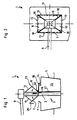
- the rain roof 1 according to the invention is shown on the one hand in a side view and on the other hand in a top view.
- the In this case, rain roof 1 is connected to the loading tube 2 of a vertical conveyor 3, which projects downwards through a loading hatch 4 of a ship 5 in the vertical direction.
- the bulk material is fed to the loading pipe 2 via a feed device 6.
- the rain roof 1 is formed from a plurality of roof sections 7, 8, 9, 10, the inclination of which can be changed by means of lifting ropes 11 and a lifting winch (not shown further).
- the lower boundary edges 12 of the rain roof are connected to the loading tube 2 in the open and in the closed state, while the upper boundary edges 13 protrude beyond the hatch edge 14 of the hatch 4.
- the connecting areas 18 of the individual roof sections 7-10 are elastic, in particular in the manner of a bellows.
- the individual roof sections 7-10 can evade upon contact with the hatch edge 14.
- the possibility is created in the form of an automatism in the event of evasion of the roof section 9, for example, to bring about a tracking of the roof section 7 in the opening sense.
- a guide device 19 which is only indicated, it is possible to move the rain roof 1 in the vertical direction relative to the loading pipe 2 of the vertical conveyor 3, in order to be able to cope with different loading conditions of the ship 5.
Landscapes
- Engineering & Computer Science (AREA)
- Mechanical Engineering (AREA)
- Ocean & Marine Engineering (AREA)
- Chemical & Material Sciences (AREA)
- Combustion & Propulsion (AREA)
- Aviation & Aerospace Engineering (AREA)
- Ship Loading And Unloading (AREA)
Claims (8)
- Auvent de protection contre la pluie pour convoyeurs verticaux, notamment pour la couverture d'écoutilles de navires, constitué de parties d'auvent (7-10) latérales, configurées à la manière d'un parapluie, disposées de manière inclinée et centrée par rapport au convoyeur vertical (3) et assemblées à ce dernier, qui peuvent être amenées dans une position déployée ou dans une position fermée par au moins un dispositif de levage,
caractérisé en ce que les parties d'auvent (7-10) sont déplacées sur le convoyeur vertical (3) de telle sorte que leurs bords de délimitation inférieurs (12) se terminent, à l'état ouvert comme à l'état fermé, contre le tube (2) du convoyeur vertical (3), tandis que leurs bords de délimitation supérieurs (13) dépassent vers l'extérieur du bord d'écoutille respectif (14), et en ce que l'eau qui s'accumule au point le plus bas de l'auvent de protection (1) peut être évacuée vers le bas ou vers l'extérieur. - Auvent de protection contre la pluie selon la revendication 1, caractérisé en ce que l'eau qui s'accumule peut être évacuée vers l'extérieur au moyen d'un tube d'évacuation (16), éventuellement télescopique.
- Auvent de protection contre la pluie selon la revendication 1, caractérisé en ce que l'eau qui s'accumule peut être évacuée vers le bas dans le fond de cale du navire (5) au moyen d'un tube d'évacuation (17) assemblé au convoyeur vertical (3).
- Auvent de protection contre la pluie selon l'une des revendications 1 à 3, caractérisé en ce que plusieurs haubans (11) sont prévus sur la périphérie du convoyeur vertical (3) ou de son tube (2), haubans dont les extrémités libres sont fixées approximativement dans la région du bord de délimitation supérieur (13) des parties d'auvent (7-10).
- Auvent de protection contre la pluie selon l'une des revendications 1 à 4, caractérisé en ce qu'en cas de contact d'une des parties d'auvent (7-10) avec le bord d'écoutille (14), la partie d'auvent chaque fois concernée (7, 8, 9, 10) est automatiquement repoussée ou rentrée, tandis que la partie d'auvent (9, 10, 7, 8) en vis-à-via peut être automatiquement abaissée.
- Auvent de protection contre la pluie selon l'une des revendications 1 à 5, caractérisé en ce que les points d'assemblage (18) des différentes parties d'auvent (7-10) sont réalisés élastiques, notamment à la manière de souflets.
- Auvent de protection contre la pluie selon l'une des revendications 1 à 6, caractérisé en ce que les différentes parties d'auvent (7-10) peuvent être déplacées en direction verticale au moyen d'un dispositif de guidage (19) entourant le convoyeur vertical (3) ou son tube (2).
- Auvent de protection contre la pluie selon l'une des revendications 1 à 7, caractérisé en ce que des dispositifs de protection contre la pluie battante (20) peuvent être fixés dans la région supérieure (13) des parties d'auvent (7-10).
Applications Claiming Priority (2)
| Application Number | Priority Date | Filing Date | Title |
|---|---|---|---|
| DE3926701A DE3926701C1 (fr) | 1989-08-12 | 1989-08-12 | |
| DE3926701 | 1989-08-12 |
Publications (2)
| Publication Number | Publication Date |
|---|---|
| EP0413131A1 EP0413131A1 (fr) | 1991-02-20 |
| EP0413131B1 true EP0413131B1 (fr) | 1992-12-02 |
Family
ID=6387019
Family Applications (1)
| Application Number | Title | Priority Date | Filing Date |
|---|---|---|---|
| EP90113211A Expired - Lifetime EP0413131B1 (fr) | 1989-08-12 | 1990-07-11 | Protection contre la pluie pour convoyeurs verticaux |
Country Status (2)
| Country | Link |
|---|---|
| EP (1) | EP0413131B1 (fr) |
| DE (2) | DE3926701C1 (fr) |
Families Citing this family (5)
| Publication number | Priority date | Publication date | Assignee | Title |
|---|---|---|---|---|
| DE4233726A1 (de) * | 1992-04-23 | 1993-10-28 | Orenstein & Koppel Ag | Verfahren zum Be- und Entladen von Materialien in und aus umschlossenen Räumen sowie Einrichtung zur Abdeckung oder Luken von umschlossenen Räumen |
| WO2002036463A1 (fr) * | 2000-10-31 | 2002-05-10 | Branita Pty Ltd T/As Reynolds Engineering Services | Couvercle pour glissoir vertical helicoidal |
| DE10127448A1 (de) * | 2001-06-07 | 2002-12-19 | Ssg Schiffahrts Und Speditions | Verfahren und Einrichtung zum Umschlagen von Umschlaggut zwischen zwei Lagerstellen |
| EP2669175B1 (fr) | 2012-05-28 | 2015-08-19 | Gustavo Possas Pereira | Système de protection pour le chargement d'un navire |
| BR202012012772U2 (pt) | 2012-05-28 | 2013-09-10 | Gustavo Possas Pereira | sistema de proteÇço para carregamento de navios |
Family Cites Families (3)
| Publication number | Priority date | Publication date | Assignee | Title |
|---|---|---|---|---|
| DE3009139A1 (de) * | 1980-03-10 | 1981-09-24 | PHB Weserhütte AG, 5000 Köln | In sich bewegliche ueberdachungsvorrichtung |
| DE3122902C2 (de) * | 1981-06-10 | 1984-11-29 | PHB Weserhütte AG, 5000 Köln | Regendach für Senkrechtförderer, Wendelrutschen o.dgl. |
| DE3323168A1 (de) * | 1983-06-28 | 1985-01-03 | Baas Technik GmbH, 2000 Wedel | Mobile abfuell- und beladevorrichtung |
-
1989
- 1989-08-12 DE DE3926701A patent/DE3926701C1/de not_active Expired - Lifetime
-
1990
- 1990-07-11 EP EP90113211A patent/EP0413131B1/fr not_active Expired - Lifetime
- 1990-07-11 DE DE9090113211T patent/DE59000538D1/de not_active Expired - Fee Related
Also Published As
| Publication number | Publication date |
|---|---|
| EP0413131A1 (fr) | 1991-02-20 |
| DE3926701C1 (fr) | 1990-05-10 |
| DE59000538D1 (de) | 1993-01-14 |
Similar Documents
| Publication | Publication Date | Title |
|---|---|---|
| DE102006001785B4 (de) | Zelt mit einem Vordachteil | |
| DE1802267A1 (de) | Zelt | |
| DE3233669A1 (de) | Stuetzanordnung fuer eine bordwand oder buehne bei lastkraftwagen und dgl. | |
| EP0413131B1 (fr) | Protection contre la pluie pour convoyeurs verticaux | |
| DE2336939A1 (de) | Abdeckung fuer schwimmbecken | |
| DE102007043818B4 (de) | Vorrichtung zum Abdecken eines Containers | |
| DE10051096A1 (de) | Vorrichtung zur Erhöhung des Fassungsvermögens eines Behälters | |
| DE2356904B2 (de) | Auslegerdrehlaufkatze | |
| DE102010030812A1 (de) | Verdeckvorrichtung für einen Lastentransportbehälter eines Lastentransportfahrzeugs und ein damit ausgerüstetes Lastentransportfahrzeug | |
| DE3009139A1 (de) | In sich bewegliche ueberdachungsvorrichtung | |
| EP0718186B1 (fr) | Arrangement pour l'écoutille d'un bateau ou pour une ouverture similaire | |
| DE19823377C1 (de) | Multifunktionsdach für Yachten | |
| DE1949052A1 (de) | Ladevorrichtung fuer Massengutfrachter | |
| WO2007082403A1 (fr) | Abri flottant pour bateau | |
| EP0744335B1 (fr) | Cage de chargement pour couvrir l'écoutille d'un bateau ou ouverture similaire | |
| DE3237010C2 (fr) | ||
| DE3122902C2 (de) | Regendach für Senkrechtförderer, Wendelrutschen o.dgl. | |
| EP0756573A1 (fr) | Dispositif de dechargement de matieres en vrac transportees dans les cales de navires | |
| EP0206094B1 (fr) | Elévateur à succion | |
| DE102018003944A1 (de) | Transportable Trägervorrichtung | |
| EP0581209B1 (fr) | Grue pour bateau, en rapport avec un bateau notamment un bateau frigoriphique | |
| DE2308558B2 (de) | Vorrichtung zum kontinuierlichen Löschen von trockenem Massengut, insbesondere aus Schiffen | |
| DE112018007815B4 (de) | Ladungs-Wetterschutzabdeckung | |
| DE4233726A1 (de) | Verfahren zum Be- und Entladen von Materialien in und aus umschlossenen Räumen sowie Einrichtung zur Abdeckung oder Luken von umschlossenen Räumen | |
| EP0436068A1 (fr) | Méthode et dispositif pour le chargement, pauvre en poussière ou sans poussière, d'enceintes enfermées |
Legal Events
| Date | Code | Title | Description |
|---|---|---|---|
| PUAI | Public reference made under article 153(3) epc to a published international application that has entered the european phase |
Free format text: ORIGINAL CODE: 0009012 |
|
| 17P | Request for examination filed |
Effective date: 19901213 |
|
| AK | Designated contracting states |
Kind code of ref document: A1 Designated state(s): BE DE FR GB NL |
|
| 17Q | First examination report despatched |
Effective date: 19920504 |
|
| GRAA | (expected) grant |
Free format text: ORIGINAL CODE: 0009210 |
|
| AK | Designated contracting states |
Kind code of ref document: B1 Designated state(s): BE DE FR GB NL |
|
| REF | Corresponds to: |
Ref document number: 59000538 Country of ref document: DE Date of ref document: 19930114 |
|
| ET | Fr: translation filed | ||
| GBT | Gb: translation of ep patent filed (gb section 77(6)(a)/1977) |
Effective date: 19930223 |
|
| PLBE | No opposition filed within time limit |
Free format text: ORIGINAL CODE: 0009261 |
|
| STAA | Information on the status of an ep patent application or granted ep patent |
Free format text: STATUS: NO OPPOSITION FILED WITHIN TIME LIMIT |
|
| RAP2 | Party data changed (patent owner data changed or rights of a patent transferred) |
Owner name: PWH ANLAGEN + SYSTEME GMBH |
|
| 26N | No opposition filed | ||
| NLT2 | Nl: modifications (of names), taken from the european patent patent bulletin |
Owner name: PWH ANLAGEN + SYSTEME GMBH TE ST. INGBERT-ROHRBACH |
|
| PGFP | Annual fee paid to national office [announced via postgrant information from national office to epo] |
Ref country code: GB Payment date: 19960613 Year of fee payment: 7 |
|
| PGFP | Annual fee paid to national office [announced via postgrant information from national office to epo] |
Ref country code: FR Payment date: 19960617 Year of fee payment: 7 |
|
| PGFP | Annual fee paid to national office [announced via postgrant information from national office to epo] |
Ref country code: BE Payment date: 19960620 Year of fee payment: 7 |
|
| PGFP | Annual fee paid to national office [announced via postgrant information from national office to epo] |
Ref country code: DE Payment date: 19960621 Year of fee payment: 7 |
|
| PGFP | Annual fee paid to national office [announced via postgrant information from national office to epo] |
Ref country code: NL Payment date: 19960627 Year of fee payment: 7 |
|
| PG25 | Lapsed in a contracting state [announced via postgrant information from national office to epo] |
Ref country code: GB Free format text: LAPSE BECAUSE OF NON-PAYMENT OF DUE FEES Effective date: 19970711 |
|
| PG25 | Lapsed in a contracting state [announced via postgrant information from national office to epo] |
Ref country code: BE Free format text: LAPSE BECAUSE OF NON-PAYMENT OF DUE FEES Effective date: 19970731 |
|
| BERE | Be: lapsed |
Owner name: ORENSTEIN & KOPPEL A.G. O&K Effective date: 19970731 |
|
| PG25 | Lapsed in a contracting state [announced via postgrant information from national office to epo] |
Ref country code: NL Free format text: LAPSE BECAUSE OF NON-PAYMENT OF DUE FEES Effective date: 19980201 |
|
| GBPC | Gb: european patent ceased through non-payment of renewal fee |
Effective date: 19970711 |
|
| PG25 | Lapsed in a contracting state [announced via postgrant information from national office to epo] |
Ref country code: FR Free format text: LAPSE BECAUSE OF NON-PAYMENT OF DUE FEES Effective date: 19980331 |
|
| NLV4 | Nl: lapsed or anulled due to non-payment of the annual fee |
Effective date: 19980201 |
|
| PG25 | Lapsed in a contracting state [announced via postgrant information from national office to epo] |
Ref country code: DE Free format text: LAPSE BECAUSE OF NON-PAYMENT OF DUE FEES Effective date: 19980401 |
|
| REG | Reference to a national code |
Ref country code: FR Ref legal event code: ST |