EP0413131B1 - Rain protection for vertical conveyors - Google Patents
Rain protection for vertical conveyors Download PDFInfo
- Publication number
- EP0413131B1 EP0413131B1 EP90113211A EP90113211A EP0413131B1 EP 0413131 B1 EP0413131 B1 EP 0413131B1 EP 90113211 A EP90113211 A EP 90113211A EP 90113211 A EP90113211 A EP 90113211A EP 0413131 B1 EP0413131 B1 EP 0413131B1
- Authority
- EP
- European Patent Office
- Prior art keywords
- rain protection
- protection means
- roof
- roof sections
- vertical conveyor
- Prior art date
- Legal status (The legal status is an assumption and is not a legal conclusion. Google has not performed a legal analysis and makes no representation as to the accuracy of the status listed.)
- Expired - Lifetime
Links
Images
Classifications
-
- B—PERFORMING OPERATIONS; TRANSPORTING
- B65—CONVEYING; PACKING; STORING; HANDLING THIN OR FILAMENTARY MATERIAL
- B65G—TRANSPORT OR STORAGE DEVICES, e.g. CONVEYORS FOR LOADING OR TIPPING, SHOP CONVEYOR SYSTEMS OR PNEUMATIC TUBE CONVEYORS
- B65G67/00—Loading or unloading vehicles
- B65G67/60—Loading or unloading ships
- B65G67/606—Loading or unloading ships using devices specially adapted for bulk material
-
- B—PERFORMING OPERATIONS; TRANSPORTING
- B63—SHIPS OR OTHER WATERBORNE VESSELS; RELATED EQUIPMENT
- B63B—SHIPS OR OTHER WATERBORNE VESSELS; EQUIPMENT FOR SHIPPING
- B63B17/00—Vessels parts, details, or accessories, not otherwise provided for
- B63B17/02—Awnings, including rigid weather protection structures, e.g. sunroofs; Tarpaulins; Accessories for awnings or tarpaulins
- B63B17/023—Hatchway tents, e.g. for weather protection of cargo during loading or unloading
Definitions
- the invention relates to a rain roof for vertical conveyors, in particular for covering ship hatches, consisting of inclined and centrally arranged to the vertical conveyor and associated umbrella-shaped side roof sections which can be brought into an unfolded or closed position by at least one lifting device.
- DE-A 30 09 139 discloses a movable roofing device for ship hatches, storage rooms, bunkers or the like, which has an outer rectangular frame and a middle frame which can be connected to it.
- the outer frame is formed on both sides in the longitudinal direction with outer guideways, in which longitudinally variable roof sections are movably mounted in both outer areas.
- the central frame has a concentric opening, which can be moved on all sides in the horizontal plane and is intended to receive a trunk or the like.
- Disadvantages of such a device are essentially due to the fact that, in the folded state, despite the harmonic design, they protrude radially relatively far beyond the tube of the vertical conveyor.
- assembly on the hatch edge appears to be relatively complex, with each roof section having such a dimension must be designed so that the tube of the vertical conveyor can be brought up to the opposite wall of the hatch.
- DE-C 31 22 902 shows a rain roof for vertical conveyors, spiral chutes or the like, in particular for ship hatches, which is formed from a plurality of lateral roof sections which are inclined and arranged centrally to the vertical conveyor and which are held or lifted in position by means of supporting cables. and can be lowered.
- the lateral roof sections are designed in the shape of an umbrella and at their upper end at a distance from the vertical conveyor are attached on one side to at least three support cables which are non-positively connected for rotating upwards and downwards with cable drums rotatably mounted on the vertical conveyor and on the other hand connected to a frame for guidance cylindrical outer jacket of the vertical conveyor by means of a vertically slidable bush and guide rollers and is provided with a central and conical inner roof.
- the object of the invention is to further develop the rain roof for vertical conveyors described in DE-C 31 22 902 in such a way that, on the one hand, the construction effort is simplified and the handling when unfolding or retracting the rain roof is reduced to a minimum. In addition, with the highest possible degree of sealing, damage should be avoided when the side roof sections touch the hatch edges.
- roof sections are shifted on the vertical conveyor in such a way that their lower boundary edges in the open and closed state with the tube of the Complete vertical conveyor, while their upper boundary edges protrude the respective hatch edge to the outside and that the water accumulating at the lowest point of the rain roof can be discharged downwards or outwards.
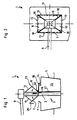
- the rain roof 1 according to the invention is shown on the one hand in a side view and on the other hand in a top view.
- the In this case, rain roof 1 is connected to the loading tube 2 of a vertical conveyor 3, which projects downwards through a loading hatch 4 of a ship 5 in the vertical direction.
- the bulk material is fed to the loading pipe 2 via a feed device 6.
- the rain roof 1 is formed from a plurality of roof sections 7, 8, 9, 10, the inclination of which can be changed by means of lifting ropes 11 and a lifting winch (not shown further).
- the lower boundary edges 12 of the rain roof are connected to the loading tube 2 in the open and in the closed state, while the upper boundary edges 13 protrude beyond the hatch edge 14 of the hatch 4.
- the connecting areas 18 of the individual roof sections 7-10 are elastic, in particular in the manner of a bellows.
- the individual roof sections 7-10 can evade upon contact with the hatch edge 14.
- the possibility is created in the form of an automatism in the event of evasion of the roof section 9, for example, to bring about a tracking of the roof section 7 in the opening sense.
- a guide device 19 which is only indicated, it is possible to move the rain roof 1 in the vertical direction relative to the loading pipe 2 of the vertical conveyor 3, in order to be able to cope with different loading conditions of the ship 5.
Description
Die Erfindung betrifft ein Regendach für Senkrechtförderer, insbesondere zur Abdeckung von Schiffsluken, bestehend aus geneigt und zentrisch zum Senkrechtförderer angeordneten sowie damit verbundenen schirmähnlich ausgestalteten seitlichen Dachabschnitten, die durch mindestens eine Hubeinrichtung in eine aufgefaltete bzw. geschlossene Position bringbar sind.The invention relates to a rain roof for vertical conveyors, in particular for covering ship hatches, consisting of inclined and centrally arranged to the vertical conveyor and associated umbrella-shaped side roof sections which can be brought into an unfolded or closed position by at least one lifting device.
Beim Be- und Entladen, insbesondere von Schiffen, ist das oft empfindliche Ladegut durch die geöffneten Ladeluken dem Wetter ausgesetzt, so daß eventuell der Betrieb unterbrochen werden muß. In manchen Fällen behelfen sich die Stauer mit einer Segeltuchabdeckung, die am Be- oder Entladegerät befestigt wird und über den Lukenrand hinausragt. Der Vorteil dieser Lösung ist in der preiswerten Ausführung zu sehen, während die Nachteile im wesentlichen darin begründet sind, daß die Relativbewegung zwischen dem Be- oder Entladegerät und dem Schiff behindert wird. Ferner nachteilig ist eine Verdunkelung des Laderaumes sowie das Eindringen von großen Wassermengen, wenn Teile der Segeltuchabdeckung innerhalb des Lukenrandes enden, was nicht immer auszuschließen ist.When loading and unloading, especially from ships, the often sensitive cargo is exposed to the weather due to the opened hatches, so that operation may have to be interrupted. In some cases, the stevedores make do with a canvas cover that is attached to the loading or unloading device and protrudes beyond the edge of the hatch. The advantage of this solution can be seen in the inexpensive design, while the disadvantages are essentially due to the fact that the relative movement between the loading or unloading device and the ship is hindered. Another disadvantage is a darkening of the cargo space and the penetration of large amounts of water when parts of the canvas cover end within the hatch edge, which can not always be excluded.
Durch die DE-A 30 09 139 ist eine in sich bewegliche Überdachungsvorrichtung für Schiffsluken, Lagerräume, Bunker oder dgl. vorbekannt, die einen äußeren rechteckig ausgestalteten Rahmen sowie einen mit diesem verbindbaren mittleren Rahmen aufweist. Der äußere Rahmen ist beidseitig in Längsrichtung mit Außenführungsbahnen ausgebildet, in denen in beiden äußeren Bereichen längsvariable Dachabschnitte beweglich gelagert sind. Der mittlere Rahmen weist eine in der horizontalen Ebene allseitig bewegbare, zur Aufnahme eines Rüssels oder dgl. eines Senkrechtförderers vorgesehene konzentrische Öffnung auf, um die herum die längs- und quervariablen Dachabschnitte in jeder Position den gesamten Überdachungsbereich abdecken. Nachteile einer solchen Vorrichtung sind im wesentlichen darin begründet, daß sie in eingefaltetem Zustand, trotz harmonikaförmig ausgebildeter Bauweise, radial relativ weit über das Rohr des Senkrechtförderers hinausragen. Ferner erscheint die Montage am Lukenrand verhältnismäßig aufwendig zu sein, wobei jeder Dachabschnitt von seiner Dimension her so ausgelegt werden muß, daß das Rohr des Senkrechtförderers bis maximal an die gegenüberliegende Wand der Luke herangeführt werden kann.DE-A 30 09 139 discloses a movable roofing device for ship hatches, storage rooms, bunkers or the like, which has an outer rectangular frame and a middle frame which can be connected to it. The outer frame is formed on both sides in the longitudinal direction with outer guideways, in which longitudinally variable roof sections are movably mounted in both outer areas. The central frame has a concentric opening, which can be moved on all sides in the horizontal plane and is intended to receive a trunk or the like. Disadvantages of such a device are essentially due to the fact that, in the folded state, despite the harmonic design, they protrude radially relatively far beyond the tube of the vertical conveyor. Furthermore, assembly on the hatch edge appears to be relatively complex, with each roof section having such a dimension must be designed so that the tube of the vertical conveyor can be brought up to the opposite wall of the hatch.
Der DE-C 31 22 902 ist ein Regendach für Senkrechtförderer, Wendelrutschen oder dgl., insbesondere für Schiffsluken, zu entnehmen, das aus mehreren geneigt und zentrisch zum Senkrechtförderer angeordneten seitlichen Dachabschnitten gebildet ist, die mittels Tragseilen in ihrer Position haltbar bzw. heb- und senkbar sind. Die seitlichen Dachabschnitte sind schirmförmig ausgestaltet und an ihrem oberen Ende mit Abstand zum Senkrechtförderer einserseits an mindestens drei Tragseilen befestigt, die zur Auf- und Abwärtsbewegung mit drehbar am Senkrechtförderer gelagerten Seiltrommeln kraftschlüssig verbunden sind und andererseits zur Führung mit einem Gestell verbunden sind, das an einem zylinderförmigen äußeren Mantel des Senkrechtförderers mittels einer vertikal gleitbaren Buchse sowie Führungsrollen geführt und mit einem zentrisch und konisch ausgebildeten inneren Dach versehen ist. Mit dieser Maßnahme kann zwar gezielt eine vollständige Lukenabdeckung realisiert werden, die jedoch bei der seitlichen Bewegung des Be- oder Entladegerätes entweder zu Problemen durch Beschädigungen bei der Berührung des bzw. der Dachabschnitte mit dem Lunkenrand oder aber in einen erheblichen steuerungstechnischen Aufwand ausartet, um durch Heben und Senken der Dachabschnitte in vertikaler Richtung dem seitlichen Verfahren des Be- oder Entladegerätes innerhalb der Laderaumluke folgen zu können. Darüberhinaus erscheint der bauliche Aufwand verhältnismäßig groß zu sein, um das Auffalten bzw. Zusammenziehen der schirmähnlich ausgebildeten Dachabschnltte bewerkstelligen zu können.DE-C 31 22 902 shows a rain roof for vertical conveyors, spiral chutes or the like, in particular for ship hatches, which is formed from a plurality of lateral roof sections which are inclined and arranged centrally to the vertical conveyor and which are held or lifted in position by means of supporting cables. and can be lowered. The lateral roof sections are designed in the shape of an umbrella and at their upper end at a distance from the vertical conveyor are attached on one side to at least three support cables which are non-positively connected for rotating upwards and downwards with cable drums rotatably mounted on the vertical conveyor and on the other hand connected to a frame for guidance cylindrical outer jacket of the vertical conveyor by means of a vertically slidable bush and guide rollers and is provided with a central and conical inner roof. With this measure, a complete hatch cover can be realized in a targeted manner, which, however, degenerates during the lateral movement of the loading or unloading device either to problems caused by damage when the roof section or sections is touched or to a considerable amount of control effort in order to pass through To be able to raise and lower the roof sections in the vertical direction to be able to follow the lateral movement of the loading or unloading device within the hold hatch. In addition, the structural effort appears to be relatively large in order to be able to unfold or contract the umbrella-like roof sections.
Der Erfindung liegt die Aufgabe zugrunde, das in der DE-C 31 22 902 beschriebene Regendach für Senkrechtförderer dahingehend weiterzubilden, daß einerseits der bauliche Aufwand vereinfacht und die Handhabungsweise beim Auffalten bzw. Einziehen des Regendaches auf ein Minimum reduziert wird. Darüberhinaus sollen bei höchstmöglichem Abdichtungsgrad Beschädigungen bei Berührung der seitlichen Dachabschnitte mit den Lukenrändern vermieden werden.The object of the invention is to further develop the rain roof for vertical conveyors described in DE-C 31 22 902 in such a way that, on the one hand, the construction effort is simplified and the handling when unfolding or retracting the rain roof is reduced to a minimum. In addition, with the highest possible degree of sealing, damage should be avoided when the side roof sections touch the hatch edges.
Diese Aufgabe wird Erfindungsgemäß dadurch gelöst, daß die Dachabschnitte dergestalt am Senkrechförderer verlagert sind, daß ihre unteren Begrenzungskanten im geöffneten sowie geschlossenen Zustand mit dem Rohr des Senkrechtförderers abschließen, während ihre oberen Begrenzungskanten den jeweiligen Lukenrand nach außen überragen und daß das sich an der tiefsten Stelle des Regendaches ansammelnde Wasser nach unten bzw. nach außen abführbar ist.This object is achieved according to the invention in that the roof sections are shifted on the vertical conveyor in such a way that their lower boundary edges in the open and closed state with the tube of the Complete vertical conveyor, while their upper boundary edges protrude the respective hatch edge to the outside and that the water accumulating at the lowest point of the rain roof can be discharged downwards or outwards.
Vorteilhafte Weiterbildungen des Erfindungsgegenstandes sind den Unteransprüchen zu entnehmen.Advantageous further developments of the subject matter of the invention can be found in the subclaims.
Durch die Art der Entfaltung (umgekehrter Regenschirm) können bei Relativbewegungen zwischen Gerät und Schiff keine Stauchungen der die Dachabschnitte haltenden Streben auftreten, da diese nur durch ihr Eigengewicht die jeweiligen Dachabschnitte aufklappen. Nebenbei läßt die Form der Abdeckung mehr Licht in den Laderaum fallen. Da hier die Dachabschnitte im wesentlichen nur durch die Zugseile gehoben bzw. gesenkt werden, besteht die Möglichkeit, unterschiedlich große Ladeluken abdecken zu können, da infolge der elastischen Verbindungen (Faltenbalg) im Bereich der Berührungspunkte der Dachabschnitte diese bis nahezu in die horizontale Position abgesenkt werden können. Das sich im mittleren Bereich des Regendaches ansammelnde Wasser kann entweder nach außen außerbords oder aber nach innen in die Bilge des Schiffes abgeführt werden. Probleme, wie sie beim St.d.T. gegeben sind, (Wasseransammlung auf den Schiffsdecks usw.) sind hiermit nicht mehr gegeben. Durch gezielte Steuerung des Regendaches (Berührungsschalter) kann bei Berührung eines Dachabschnittes mit dem Lukenrand der diesem gegenüberliegende Dachabschnitt um den gleichen Betrag abgesenkt werden wie der erste Dachabschnitt angehoben wird. Durch Verwendung eines Schlagregenschutzes im Bereich der oberen Begrenzungskante der einzelnen Dachabschnitte kann in jedem Fall sichergestellt werden, daß kein Wasser in den Laderaum eindringen kann.Due to the type of unfolding (inverted umbrella), relative movements between the device and the ship do not cause struts in the struts holding the roof sections, since these only open the respective roof sections by their own weight. Besides, the shape of the cover allows more light to fall into the cargo area. Since here the roof sections are essentially only raised or lowered by the traction ropes, there is the possibility of being able to cover hatches of different sizes, since due to the elastic connections (bellows) in the area of the contact points of the roof sections, these are lowered almost to the horizontal position can. The water that accumulates in the central area of the rain roof can either be discharged to the outside or to the inside of the ship's bilge. Problems like the St.d.T. (water accumulation on the ship's decks, etc.) are no longer given. Through targeted control of the rain roof (touch switch), when a roof section touches the hatch edge, the roof section opposite it can be lowered by the same amount as the first roof section is raised. The use of driving rain protection in the area of the upper boundary edge of the individual roof sections can ensure in any case that no water can penetrate into the loading space.
Die Erfindung ist anhand einer Prinzipskizze in der Zeichnung dargestellt und wird wie folgt beschrieben. Es zeigen:
- Fig. 1 und 2 - unterschiedliche Ansichten des erfindungsgemäßen Regendaches.
- 1 and 2 - different views of the rain roof according to the invention.
In den Figuren 1 und 2 ist das erfindungsgemäße Regendach 1 einerseits in der Seitenansicht und andererseits in der Draufsicht dargestellt. Das Regendach 1 ist in diesem Fall mit dem Beladerohr 2 eines Senkrechtförderers 3 verbunden, welcher durch eine Ladeluke 4 eines Schiffes 5 in vertikaler Richtung nach unten hineinragt. Das schüttförmige Gut wird über eine Zuführeinrichtung 6 dem Beladerohr 2 zugeführt. Das Regendach 1 ist aus mehreren Dachabschnitten 7,8,9,10 gebildet, die mittels Hubseilen 11 sowie einer nicht weiter dargestellten Hubwinde in ihrer Neigung veränderbar sind. Die unteren Begrenzungskanten 12 des Regendaches sind im geöffneten sowie im geschlossenen Zustand mit dem Beladerohr 2 verbunden, während die oberen Begrenzungskanten 13 über den Lukenrand 14 der Luke 4 hinwegragen.In FIGS. 1 and 2, the rain roof 1 according to the invention is shown on the one hand in a side view and on the other hand in a top view. The In this case, rain roof 1 is connected to the
Infolge dieser umgekehrten Regenschirmanordnung kann einerseits Tageslicht von oben durch die Luke in den Laderaum 15 des Schiffes 5 eindringen und andererseits das sich im Innern des Regendaches 1 ansammelnde Wasser entweder mittels einer ggf. teleskopierbaren Rohrleitung 16 nach außen oder alternativ mittels einer Rohrleitung 17 in die Bilge des Schiffes 5 abgeführt werden.As a result of this reverse arrangement of the umbrella, daylight can penetrate from above through the hatch into the
Die Verbindungsbereiche 18 der einzelnen Dachabschnitte 7-10 sind elastisch, insbesondere nach Art eines Faltenbalges, ausgebildet. Die einzelnen Dachabschnitte 7-10 können bei Berührung mit dem Lukenrand 14 ausweichen. Außerdem wird die Möglichkeit gebildet, in Form eines Automatismus bei Ausweichen beispielsweise des Dachabschnittes 9 ein Nachführen des Dachabschnittes 7 im öffnenden Sinne herbeizuführen. Mittels einer nur angedeuteten Führungseinrichtung 19 besteht die Möglichkeit, das Regendach 1 in vertikaler Richtung relativ zum Beladerohr 2 des Senkrechtförderers 3 zu verschieben, um so unterschiedlichen Beladezuständen des Schiffes 5 gerecht werden zu können. Für extreme Wetterverhältnisse besteht die Möglichkeit, im Bereich der oberen Begrenzungskante 13 einen zusätzlichen Schlagregenschutz 20 vorzusehen.The connecting
Claims (8)
- Rain protection means for vertical conveyors, especially for covering ships hatches, consisting of inclined screen-like lateral roof sections (7-10) which are arranged centrally with respect to the vertical conveyor (3) and connected thereto, and which can be brought into a folded-up or closed position by means of at least one lifting device, characterised in that the roof sections (7-10) are arranged on the vertical conveyor (3) in such a way that their lower limit edges (12), both in the open and in the closed state, close with the pipe (2) of the vertical conveyor (3), while their upper limit edges (13) project outwards over the respective edge (14) of the hatch, and that water collecting at the lowest point of the rain protection means (1) can be led off downwards or outwards.
- Rain protection means according to Claim 1, characterised in that the water collecting can be led off outwards by means of an optionally telescopic discharge pipe (16).
- Rain protection means according to Claim 1, characterised in that the water collecting can be led off downwards into the bilges of the ship (5) through a discharge pipe (17) connected to the vertical conveyor (3).
- Rain protection means according to Claims 1 to 3, characterised in that on the periphery of the vertical conveyor (3) or its pipe (2) a plurality of bracing ropes (11) are provided, the free ends of which are fastened approximately in the region of the upper limit edge (13) of the roof sections (7-10).
- Rain protection means according to Claims 1 to 4, characterised in that when one of the roof sections (7-10) comes into contact with the edge (14) of the hatch, the relevant roof section (7,8,9,10) is in each case automatically pushed away or automatically pulled in, while the roof section (9,10,7,8) situated opposite thereto can be automatically lowered.
- Rain protection means according to Claims 1 to 5, characterised in that the points of connection (18) of the individual roof sections (7-10) are made resilient, especially concertina-like.
- Rain protection means according to Claims 1 to 6, characterised in that all roof sections (7-10) are movable in a vertical direction by means of a guide arrangement (19) arranged round the vertical conveyor (3) or its pipe (2).
- Rain protection means according to Claims 1 to 7, characterised in that means for protection against driving rain (20) can be secured in the upper region (13) of the roof sections (7-10).
Applications Claiming Priority (2)
| Application Number | Priority Date | Filing Date | Title |
|---|---|---|---|
| DE3926701 | 1989-08-12 | ||
| DE3926701A DE3926701C1 (en) | 1989-08-12 | 1989-08-12 |
Publications (2)
| Publication Number | Publication Date |
|---|---|
| EP0413131A1 EP0413131A1 (en) | 1991-02-20 |
| EP0413131B1 true EP0413131B1 (en) | 1992-12-02 |
Family
ID=6387019
Family Applications (1)
| Application Number | Title | Priority Date | Filing Date |
|---|---|---|---|
| EP90113211A Expired - Lifetime EP0413131B1 (en) | 1989-08-12 | 1990-07-11 | Rain protection for vertical conveyors |
Country Status (2)
| Country | Link |
|---|---|
| EP (1) | EP0413131B1 (en) |
| DE (2) | DE3926701C1 (en) |
Families Citing this family (5)
| Publication number | Priority date | Publication date | Assignee | Title |
|---|---|---|---|---|
| DE4233726A1 (en) * | 1992-04-23 | 1993-10-28 | Orenstein & Koppel Ag | Process for loading and unloading materials in and from enclosed spaces, and device for covering or opening hatches in enclosed spaces |
| WO2002036463A1 (en) * | 2000-10-31 | 2002-05-10 | Branita Pty Ltd T/As Reynolds Engineering Services | Cover for vertical spiral chute |
| DE10127448A1 (en) * | 2001-06-07 | 2002-12-19 | Ssg Schiffahrts Und Speditions | Process and device for handling cargo between two storage locations |
| EP2669175B1 (en) | 2012-05-28 | 2015-08-19 | Gustavo Possas Pereira | Protection system for ship loading |
| BR202012012772U2 (en) | 2012-05-28 | 2013-09-10 | Gustavo Possas Pereira | ship loading protection system |
Family Cites Families (3)
| Publication number | Priority date | Publication date | Assignee | Title |
|---|---|---|---|---|
| DE3009139A1 (en) * | 1980-03-10 | 1981-09-24 | PHB Weserhütte AG, 5000 Köln | Cover with conveyor aperture for hold of ship - has concertina construction permitting continuous conveyor movement in two dimensions |
| DE3122902C2 (en) * | 1981-06-10 | 1984-11-29 | PHB Weserhütte AG, 5000 Köln | Rain cover for vertical conveyors, spiral chutes or the like. |
| DE3323168A1 (en) * | 1983-06-28 | 1985-01-03 | Baas Technik GmbH, 2000 Wedel | Mobile drawing off and loading device |
-
1989
- 1989-08-12 DE DE3926701A patent/DE3926701C1/de not_active Expired - Lifetime
-
1990
- 1990-07-11 DE DE9090113211T patent/DE59000538D1/en not_active Expired - Fee Related
- 1990-07-11 EP EP90113211A patent/EP0413131B1/en not_active Expired - Lifetime
Also Published As
| Publication number | Publication date |
|---|---|
| EP0413131A1 (en) | 1991-02-20 |
| DE59000538D1 (en) | 1993-01-14 |
| DE3926701C1 (en) | 1990-05-10 |
Similar Documents
| Publication | Publication Date | Title |
|---|---|---|
| DE102006001785B4 (en) | Tent with a canopy section | |
| DE1802267A1 (en) | tent | |
| EP0413131B1 (en) | Rain protection for vertical conveyors | |
| DE2336939A1 (en) | COVER FOR SWIMMING POOL | |
| DE2356904A1 (en) | Slewing rail-mounted crane - has telescopic jib retracting to less than half full length | |
| DE102007043818B4 (en) | Device for covering a container | |
| DE10051096A1 (en) | Device for increasing the capacity of a container | |
| DE102010030812A1 (en) | Covering device for tilting bridge-type transport container of e.g. three sided dump truck vehicle, has operating device that does not laterally overlap at surface such that plate is not folded when tarpaulin is found in covering position | |
| DE3009139A1 (en) | Cover with conveyor aperture for hold of ship - has concertina construction permitting continuous conveyor movement in two dimensions | |
| EP0718186B1 (en) | Arrangement for the hatch of a ship or a similar opening | |
| DE19823377C1 (en) | Roof for marine vessel | |
| DE2811012A1 (en) | DRIVABLE HULL FOR CARGO SHIPS | |
| WO2007082403A1 (en) | Floating boat garage | |
| EP0744335B1 (en) | Loading shaft for covering a ship's hatch or similar opening | |
| DE3237010C2 (en) | ||
| DE3122902C2 (en) | Rain cover for vertical conveyors, spiral chutes or the like. | |
| DE19641011C2 (en) | Mobile sales stand | |
| EP0756573A1 (en) | Device for unloading bulk materials from ship cargo holds | |
| EP0206094B1 (en) | Suction elevator | |
| DE102018003944A1 (en) | Transportable carrier device | |
| EP0581209B1 (en) | Ship's crane, in conjunction with a ship, especially a refrigerated cargo ship | |
| DE2308558B2 (en) | Device for the continuous discharge of dry bulk cargo, in particular from ships | |
| DE112018007815B4 (en) | Cargo weather protection cover | |
| DE4233726A1 (en) | Process for loading and unloading materials in and from enclosed spaces, and device for covering or opening hatches in enclosed spaces | |
| DE4344171C2 (en) | Device for holding hatch covers |
Legal Events
| Date | Code | Title | Description |
|---|---|---|---|
| PUAI | Public reference made under article 153(3) epc to a published international application that has entered the european phase |
Free format text: ORIGINAL CODE: 0009012 |
|
| 17P | Request for examination filed |
Effective date: 19901213 |
|
| AK | Designated contracting states |
Kind code of ref document: A1 Designated state(s): BE DE FR GB NL |
|
| 17Q | First examination report despatched |
Effective date: 19920504 |
|
| GRAA | (expected) grant |
Free format text: ORIGINAL CODE: 0009210 |
|
| AK | Designated contracting states |
Kind code of ref document: B1 Designated state(s): BE DE FR GB NL |
|
| REF | Corresponds to: |
Ref document number: 59000538 Country of ref document: DE Date of ref document: 19930114 |
|
| ET | Fr: translation filed | ||
| GBT | Gb: translation of ep patent filed (gb section 77(6)(a)/1977) |
Effective date: 19930223 |
|
| PLBE | No opposition filed within time limit |
Free format text: ORIGINAL CODE: 0009261 |
|
| STAA | Information on the status of an ep patent application or granted ep patent |
Free format text: STATUS: NO OPPOSITION FILED WITHIN TIME LIMIT |
|
| RAP2 | Party data changed (patent owner data changed or rights of a patent transferred) |
Owner name: PWH ANLAGEN + SYSTEME GMBH |
|
| 26N | No opposition filed | ||
| NLT2 | Nl: modifications (of names), taken from the european patent patent bulletin |
Owner name: PWH ANLAGEN + SYSTEME GMBH TE ST. INGBERT-ROHRBACH |
|
| PGFP | Annual fee paid to national office [announced via postgrant information from national office to epo] |
Ref country code: GB Payment date: 19960613 Year of fee payment: 7 |
|
| PGFP | Annual fee paid to national office [announced via postgrant information from national office to epo] |
Ref country code: FR Payment date: 19960617 Year of fee payment: 7 |
|
| PGFP | Annual fee paid to national office [announced via postgrant information from national office to epo] |
Ref country code: BE Payment date: 19960620 Year of fee payment: 7 |
|
| PGFP | Annual fee paid to national office [announced via postgrant information from national office to epo] |
Ref country code: DE Payment date: 19960621 Year of fee payment: 7 |
|
| PGFP | Annual fee paid to national office [announced via postgrant information from national office to epo] |
Ref country code: NL Payment date: 19960627 Year of fee payment: 7 |
|
| PG25 | Lapsed in a contracting state [announced via postgrant information from national office to epo] |
Ref country code: GB Free format text: LAPSE BECAUSE OF NON-PAYMENT OF DUE FEES Effective date: 19970711 |
|
| PG25 | Lapsed in a contracting state [announced via postgrant information from national office to epo] |
Ref country code: BE Free format text: LAPSE BECAUSE OF NON-PAYMENT OF DUE FEES Effective date: 19970731 |
|
| BERE | Be: lapsed |
Owner name: ORENSTEIN & KOPPEL A.G. O&K Effective date: 19970731 |
|
| PG25 | Lapsed in a contracting state [announced via postgrant information from national office to epo] |
Ref country code: NL Free format text: LAPSE BECAUSE OF NON-PAYMENT OF DUE FEES Effective date: 19980201 |
|
| GBPC | Gb: european patent ceased through non-payment of renewal fee |
Effective date: 19970711 |
|
| PG25 | Lapsed in a contracting state [announced via postgrant information from national office to epo] |
Ref country code: FR Free format text: LAPSE BECAUSE OF NON-PAYMENT OF DUE FEES Effective date: 19980331 |
|
| NLV4 | Nl: lapsed or anulled due to non-payment of the annual fee |
Effective date: 19980201 |
|
| PG25 | Lapsed in a contracting state [announced via postgrant information from national office to epo] |
Ref country code: DE Free format text: LAPSE BECAUSE OF NON-PAYMENT OF DUE FEES Effective date: 19980401 |
|
| REG | Reference to a national code |
Ref country code: FR Ref legal event code: ST |