EP0412408A2 - Elektrisch leitfähige Polymere und ihre Verwendung als Orientierungsschicht in Flüssigkristall-Schalt- und Anzeigeelementen - Google Patents
Elektrisch leitfähige Polymere und ihre Verwendung als Orientierungsschicht in Flüssigkristall-Schalt- und Anzeigeelementen Download PDFInfo
- Publication number
- EP0412408A2 EP0412408A2 EP90114643A EP90114643A EP0412408A2 EP 0412408 A2 EP0412408 A2 EP 0412408A2 EP 90114643 A EP90114643 A EP 90114643A EP 90114643 A EP90114643 A EP 90114643A EP 0412408 A2 EP0412408 A2 EP 0412408A2
- Authority
- EP
- European Patent Office
- Prior art keywords
- liquid crystal
- orientation layer
- integer
- conductive polymer
- electrically conductive
- Prior art date
- Legal status (The legal status is an assumption and is not a legal conclusion. Google has not performed a legal analysis and makes no representation as to the accuracy of the status listed.)
- Granted
Links
- 0 *C1=C*C=C1* Chemical compound *C1=C*C=C1* 0.000 description 1
Images

Classifications
-
- G—PHYSICS
- G02—OPTICS
- G02F—OPTICAL DEVICES OR ARRANGEMENTS FOR THE CONTROL OF LIGHT BY MODIFICATION OF THE OPTICAL PROPERTIES OF THE MEDIA OF THE ELEMENTS INVOLVED THEREIN; NON-LINEAR OPTICS; FREQUENCY-CHANGING OF LIGHT; OPTICAL LOGIC ELEMENTS; OPTICAL ANALOGUE/DIGITAL CONVERTERS
- G02F1/00—Devices or arrangements for the control of the intensity, colour, phase, polarisation or direction of light arriving from an independent light source, e.g. switching, gating or modulating; Non-linear optics
- G02F1/01—Devices or arrangements for the control of the intensity, colour, phase, polarisation or direction of light arriving from an independent light source, e.g. switching, gating or modulating; Non-linear optics for the control of the intensity, phase, polarisation or colour
- G02F1/13—Devices or arrangements for the control of the intensity, colour, phase, polarisation or direction of light arriving from an independent light source, e.g. switching, gating or modulating; Non-linear optics for the control of the intensity, phase, polarisation or colour based on liquid crystals, e.g. single liquid crystal display cells
- G02F1/133—Constructional arrangements; Operation of liquid crystal cells; Circuit arrangements
- G02F1/1333—Constructional arrangements; Manufacturing methods
- G02F1/1337—Surface-induced orientation of the liquid crystal molecules, e.g. by alignment layers
- G02F1/133711—Surface-induced orientation of the liquid crystal molecules, e.g. by alignment layers by organic films, e.g. polymeric films
-
- C—CHEMISTRY; METALLURGY
- C09—DYES; PAINTS; POLISHES; NATURAL RESINS; ADHESIVES; COMPOSITIONS NOT OTHERWISE PROVIDED FOR; APPLICATIONS OF MATERIALS NOT OTHERWISE PROVIDED FOR
- C09K—MATERIALS FOR MISCELLANEOUS APPLICATIONS, NOT PROVIDED FOR ELSEWHERE
- C09K19/00—Liquid crystal materials
- C09K19/04—Liquid crystal materials characterised by the chemical structure of the liquid crystal components, e.g. by a specific unit
- C09K19/38—Polymers
-
- C—CHEMISTRY; METALLURGY
- C09—DYES; PAINTS; POLISHES; NATURAL RESINS; ADHESIVES; COMPOSITIONS NOT OTHERWISE PROVIDED FOR; APPLICATIONS OF MATERIALS NOT OTHERWISE PROVIDED FOR
- C09K—MATERIALS FOR MISCELLANEOUS APPLICATIONS, NOT PROVIDED FOR ELSEWHERE
- C09K2323/00—Functional layers of liquid crystal optical display excluding electroactive liquid crystal layer characterised by chemical composition
- C09K2323/02—Alignment layer characterised by chemical composition
-
- G—PHYSICS
- G02—OPTICS
- G02F—OPTICAL DEVICES OR ARRANGEMENTS FOR THE CONTROL OF LIGHT BY MODIFICATION OF THE OPTICAL PROPERTIES OF THE MEDIA OF THE ELEMENTS INVOLVED THEREIN; NON-LINEAR OPTICS; FREQUENCY-CHANGING OF LIGHT; OPTICAL LOGIC ELEMENTS; OPTICAL ANALOGUE/DIGITAL CONVERTERS
- G02F1/00—Devices or arrangements for the control of the intensity, colour, phase, polarisation or direction of light arriving from an independent light source, e.g. switching, gating or modulating; Non-linear optics
- G02F1/01—Devices or arrangements for the control of the intensity, colour, phase, polarisation or direction of light arriving from an independent light source, e.g. switching, gating or modulating; Non-linear optics for the control of the intensity, phase, polarisation or colour
- G02F1/13—Devices or arrangements for the control of the intensity, colour, phase, polarisation or direction of light arriving from an independent light source, e.g. switching, gating or modulating; Non-linear optics for the control of the intensity, phase, polarisation or colour based on liquid crystals, e.g. single liquid crystal display cells
- G02F1/137—Devices or arrangements for the control of the intensity, colour, phase, polarisation or direction of light arriving from an independent light source, e.g. switching, gating or modulating; Non-linear optics for the control of the intensity, phase, polarisation or colour based on liquid crystals, e.g. single liquid crystal display cells characterised by the electro-optical or magneto-optical effect, e.g. field-induced phase transition, orientation effect, guest-host interaction or dynamic scattering
- G02F1/139—Devices or arrangements for the control of the intensity, colour, phase, polarisation or direction of light arriving from an independent light source, e.g. switching, gating or modulating; Non-linear optics for the control of the intensity, phase, polarisation or colour based on liquid crystals, e.g. single liquid crystal display cells characterised by the electro-optical or magneto-optical effect, e.g. field-induced phase transition, orientation effect, guest-host interaction or dynamic scattering based on orientation effects in which the liquid crystal remains transparent
- G02F1/141—Devices or arrangements for the control of the intensity, colour, phase, polarisation or direction of light arriving from an independent light source, e.g. switching, gating or modulating; Non-linear optics for the control of the intensity, phase, polarisation or colour based on liquid crystals, e.g. single liquid crystal display cells characterised by the electro-optical or magneto-optical effect, e.g. field-induced phase transition, orientation effect, guest-host interaction or dynamic scattering based on orientation effects in which the liquid crystal remains transparent using ferroelectric liquid crystals
Definitions
- ferroelectric liquid crystals serve as switching and display medium (FLC displays) are described, for example, in US Pat. No. 4,367,924. They contain a layer of a ferroelectric liquid-crystalline medium (FLC), which is enclosed on both sides by electrically insulating layers, electrodes and boundary plates, usually glass plates. They also contain one polarizer when in guest host mode and two polarizers when in birefringence mode.
- the electrically insulating layers are intended to prevent electrical short circuits between the electrodes and the diffusion of ions from the glass of the boundary plates into the liquid-crystalline layer.
- At least one and preferably both of the insulating layers serve as an orientation layer, which brings the liquid-crystalline material into a configuration in which the molecules of the liquid-crystalline layer lie with their longitudinal axes parallel to one another, and in which the smectic planes are arranged perpendicular or obliquely to the orientation layer.
- orientation layer which brings the liquid-crystalline material into a configuration in which the molecules of the liquid-crystalline layer lie with their longitudinal axes parallel to one another, and in which the smectic planes are arranged perpendicular or obliquely to the orientation layer.
- FLC displays can therefore be switched bistably. The switching times are in the ⁇ s range and are shorter the higher the spontaneous polarization of the liquid-crystalline material used.
- FLC displays Compared to the previously used liquid crystal displays. which are usually not ferroelectric, FLC displays have the particular advantage that the achievable multiplex ratio, i. H. the maximum number of lines which can be controlled in the time-sequential method (“multiplex method”) is very much larger than in the known non-ferroelectric displays.
- a disadvantage of FLC displays can, however, result from the fact that a display which has been in one of the two stable states for a long time (standing picture) is very difficult, i. H. with a very high amplitude or very long pulse duration of the applied voltage is to be switched to the other state, that is to say shows a pronounced optical hysteresis.
- the orientation layers preferably contain an electrically conductive polymer which consists of repeating units of the formula (I): in which R1, R2 independently of one another H or straight-chain or branched alkyl or alkoxy with 1-16 C atoms or halogen, XS or NH Y ⁇ BF - 4th , PF - 6 , PO 3- 4th , AsF - 6 , SbCl - 6 SO 2- 4th HSO - 4th , Alkyl-SO - 3rd , Perfluoroalkyl-SO - 3rd , Aryl-SO - 3rd , F ⁇ or Cl ⁇ , n is an integer from 4 to 100 and m is an integer from 1 to 30.
- R1, R2 independently of one another H or straight-chain or branched alkyl or alkoxy with 1-16 C atoms or halogen, XS or NH Y ⁇ BF - 4th , PF - 6 , PO 3- 4th ,
- Electrically conductive polymers that are in oxidized form in dipolar aprotic solvents Are room temperature soluble and which are derived from a monomer of formula (II) where at least one of the two radicals R3 and R4 is an alkoxy group and the other is optionally (C1-C6) alkyl or hydrogen, have already been described in DE-A 3 717 668, DE-A 3 628 895 and DE-A 3 736 114. The presentation, stability and electrical conductivity of the various positively doped polymers were also examined at this point.
- Electrically conductive polymers of the formula (I) with a (positive) degree of doping of 10 to 30% are particularly suitable for use in liquid crystal switching and display elements, the degree of doping being the ratio of the electrical charge (m) of the polymer to the number of monomer units from which it is built.
- the undoped polymers have only a negligibly low electrical conductivity; highly doped polymers (polymeric radical cations) are mostly unstable or difficult to access.
- Such conductive polymers are particularly preferably used as a component of the orientation layers in FLC displays in which n in the formula (I) is an integer from 4 to 30 and m is an integer from 1 to 9, very particularly preferred for n is one integer from 4 to 10 and for m an integer from 1 to 4.
- conductive polymers in which X in the formula (I) is a sulfur atom, and which is the anion (Y ⁇ ) BF - 4th , PO 3- 4th , SO 2- 4th , HSO - 4th , F ⁇ and / or Cl ⁇ included.
- the orientation layer preferably contains 30 to 100% by weight of the conductive polymer of the general formula (I).
- Other components that can be used are both electrically conductive materials and non-conductive substances, in particular organic polymers.
- the orientation layer in the liquid crystal switching and display element contains, in addition to a polymer of the formula (I), a non-conductive polymer such as, for example, polyvinyl formal, polyvinyl acetal, polyvinyl butyral, polyvinyl acetate, polyvinyl chloride, Poly-vinyl methyl ether, poly-vinyl methyl ketone, poly-maleic anhydride, poly-styrene, poly-N-vinyl carbazole, poly-N-vinyl pyrrolidone, poly vinyl pyridine, poly methacrylate, poly methyl methacrylate, poly acrylonitrile, polyacetaldehyde, poly acrolein, Poly-ethylene oxide, poly-tetrahydrofuran, aliphatic polyester, poly-carbonate, poly-butyl isocyanate, natural rubber, poly-urethane, methyl cellulose, ethyl cellulose, cellulose triacetate or poly-
- the orientation layer can also contain other conductive polymers.
- one of the orientation layers may consist of an electrically conductive polymer, while the other is an electrically insulating layer.
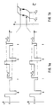
- An FLC display is subjected to a sequence of bipolar voltage pulses (Fig. 1a), in each case follows an "reset pulse" R, which is so large that the display switches in any case, an inverse test pulse T. Is the Voltage of the test pulse (V t ) high enough, the display switches in the opposite direction to the reset pulse, which causes the display to flash.
- the minimum voltage (critical voltage of the test pulse) V t c (FIG. 1b) that is required for switching by the test pulse depends on the history of switching the display. If the initial situation is such that the test pulses are too small to switch, so that there is a static display, the increase in the test pulse voltage V t only leads to relatively high values V c t2 (Fig.
- the ordinate is the intensity (in volts; which is proportional to the transmission) and the abscissa is the electrical field strength (in volts / ⁇ m).
- Fig. 2 shows in comparison the hysteresis curve obtained by the method explained above of a known display, in which the electrodes are insulated from the FLC by an orientation layer (FIG. 2a), and of a display according to the invention, in which two orientation layers made of rubbed conductive polymer in are in direct contact with the FLC (Fig. 2b).
- the extensive suppression of hysteresis in the latter case is clearly recognizable.
- a 2% nitromethane solution of an electrically conductive polymer with the following structural formula, where n is 5 or 6, is by a spin coating process with 1500 revolutions / minute on a 1 mm thick Glass substrate, which had previously been provided with a transparent electrode, spun on for 30 seconds.
- the substrate and the layer of the solution deposited thereon are annealed at 120 ° C. in a drying cabinet in order to drive the solvent by distillation.
- a polymer layer with a layer thickness of 100 nm is obtained, which is then rubbed lightly twice in the same direction using a grinder.
- a homogeneous, slightly bluish polymer layer with a thickness of 100 nm and a specific electrical conductivity of 8.0 x 10 -3 S / cm is obtained.
- the solution is applied in the same way as described in Example 1 on a glass substrate which has previously been provided with a transparent electrode. After annealing for one hour at 180 ° C., the layer thickness is 150 nm.
- a liquid crystal cell with A 2 ⁇ m thick liquid crystal layer is produced by aligning the substrates in the same manner as in Example 1.
- the cell is filled with the commercially available ®Felix 002 ferroelectric liquid crystal mixture (manufacturer: Hoechst AG). A good bistability is found.
- the liquid crystal switching element shows almost no optical hysteresis. 77% are measured as the optical transparency of the orientation layer at a light wavelength of 550 nm.
Abstract
Description
- Schalt- und Anzeigeelemente, bei denen ferroelektrische Flüssigkristalle als Schalt- und Anzeigemedium dienen (FLC-Displays), werden beispielsweise in US-A 4,367,924 beschrieben. Sie enthalten eine Schicht aus einem ferroelektrischen flüssigkristallinen Medium (FLC), die beiderseitig von elektrisch isolierenden Schichten, Elektroden und Begrenzungsscheiben, üblicherweise Glasscheiben, eingeschlossen ist. Außerdem enthalten sie einen Polarisator, wenn sie im Guest-Host-Mode, und zwei Polarisatoren, wenn sie im Doppelbrechungs-Mode betrieben werden. Die elektrisch isolierenden Schichten sollen elektrische Kurzschlüsse zwischen den Elektroden und die Diffusion von Ionen aus dem Glas der Begrenzungsscheiben in die flüssigkristalline Schicht verhindern. Ferner dient mindestens eine und vorzugsweise beide der isolierenden Schichten als Orientierungsschicht, die das flüssigkristalline Material in eine Konfiguration bringt, bei der die Moleküle der flüssigkristallinen Schicht mit ihren Längsachsen parallel zueinander liegen, und in der die smektischen Ebenen senkrecht oder schräg zur Orientierungsschicht angeordnet sind. In dieser Anordnung gibt es für die FLC-Moleküle zwei mögliche und gleichwertige Orientierungen, in die sie durch pulsartiges Anlegen eines elektrisches Feldes gebracht werden können. Sie verharren jeweils in der zuletzt erzeugten Orientierung, auch wenn das Feld abgeschaltet oder das Display kurzgeschlossen wird. FLC-Displays sind also bistabil schaltbar. Die Schaltzeiten liegen im Bereich von µs und sind um so kürzer, je höher die spontane Polarisation des verwendeten flüssigkristallinen Materials ist.
- Gegenüber den bisher verwendeten Flüssigkristalldisplays. die in der Regel nicht ferroelektrisch sind, haben FLC-Displays insbesondere den Vorzug, daß das erreichbare Multiplexverhältnis, d. h. die maximale Zahl der im zeitlich sequentiellen Verfahren ("Multiplex-Verfahren") ansteuerbaren Zeilen, sehr viel größer ist als bei den bekannten nicht-ferroelektrischen Displays.
- Ein Nachteil von FLC-Displays kann sich jedoch daraus ergeben, daß ein Display, das sich längere Zeit in einem der beiden stabilen Zustände befunden hat (stehendes Bild), nur sehr schwer, d. h. mit sehr hoher Amplitude oder sehr langer Pulsdauer der angelegten Spannung in den anderen Zustand umzuschalten ist, also eine ausgeprägte optische Hysterese zeigt. Bei bildhaften Anzeigen führt das dazu, daß ein längere Zeit eingeschriebenes Bild im Nachfolgebild schemenhaft als sog. "Geisterbild" zu erkennen ist. Diese Erscheinung der optischen Hysterese ist um so stärker ausgeprägt, je höher die spontane Polarisation des FLC-Materials ist. Da andererseits die Schaltzeit von FLC-Materialien zur spontanen Polarisation umgekehrt proportional ist, wird ein wichtiger Vorteil der FLC-Displays durch diese Hysterese wieder zunichte gemacht. Die Ursache dieses Phänomens ist bisher nicht eindeutig geklärt; es gibt Anzeichen dafür, daß ionische Verunreinigungen im FLC dafür verantwortlich sind.
- Es wurde bereits in der prioritätsälteren, nicht-vorveröfftentlichten DE-A 3 843 228 vorgeschlagen, die beschriebene Erscheinung der optischen Hysterese in FLC-Displays dadurch stark zu vermindern oder zu unterdrücken, daß mindestens eine der Elektroden in unmittelbaren elektrischen Kontakt mit dem flüssigkristallinen Medium gebracht wird. Es wurde nun überraschenderweise gefunden, daß man die optische Hysterese in FLC-Displays besonders effektiv dadurch unterdrücken kann, daß man ein Flüssigkristall-Schalt- und -Anzeigeelement verwendet, daß ein ferroelektrisches flüssigkristallines Medium, zwei Elektroden, mindestens einen Polarisator, zwei transparente Trägerplatten und mindestens eine Orientierungsschicht enthält, wobei mindestens eine der Orientierungsschichten in unmittelbarem elektrischen Kontakt mit der zugehörigen Elektrode steht und diese Orientierungsschicht ein elektrisch leitfähiges Polymer enthält.
- Bevorzugterweise enthalten die Orientierungsschichten ein elektrisch leitfähiges Polymer, das aus wiederkehrenden Einheiten der Formel (I) besteht:

R¹, R² unabhängig voneinander H oder geradkettiges oder verzweigtes Alkyl oder Alkoxy mit 1-16 C-Atomen oder Halogen,
X S oder NH
Y⁻ BF


n eine ganze Zahl von 4 bis 100 und
m eine ganze Zahl von 1 bis 30 bedeuten. - Elektrisch leitfähige Polymere, die in oxidierter Form in dipolar aprotischen Lösungsmitteln bei Raumtemperatur löslich sind und die sich von einem Monomer der Formel (II) ableiten

- Für die Anwendung in Flüssigkristall-Schalt- und Anzeigelementen sind elektrisch leitfähige Polymere der Formel (I) mit einem (positiven) Dotierungsgrad von 10 bis 30 % besonders geeignet, wobei der Dotierungsgrad das Verhältnis von elektrischer Ladung (m) des Polymers zur Anzahl der Monomereinheiten, aus denen es aufgebaut ist (n), angibt. Die undotierten Polymere besitzen nur eine vernachlässigbar kleine elektrische Leitfähigkeit, hochdotierte Polymere (polymere Radikalkationen) sind zumeist instabil oder schwer zugänglich.
- Besonders bevorzugt werden solche leitfähigen Polymere als Bestandteil der Orientierungsschichten in FLC-Displays eingesetzt, bei denen in der Formel (I) n eine ganze Zahl von 4 bis 30 und m eine ganze Zahl von 1 bis 9 bedeuten, ganz besonders bevorzugt wird für n eine ganze Zahl von 4 bis 10 und für m eine ganze Zahl von 1 bis 4.
- Bevorzugt werden ferner leitfähige Polymere eingesetzt, bei denen X in der Formel (I) ein Schwefelatom bedeutet, und die als Anion (Y ⁻ ) BF


- Bevorzugterweise enthält die Orientierungsschicht 30 bis 100 Gew.-% des leitfähigen Polymers der allgemeinen Formel (I). Als andere Komponenten kommen sowohl elektrisch leitfähige Materialien wie auch nicht leitende Stoffe, insbesondere organische Polymere, in Frage.
- Die Orientierungsschicht enthält im Flüssigkristall-Schalt- und -Anzeigeelement in einer weiteren Ausführungsform der Erfindung neben einem Polymer der Formel (I) ein nichtleitfähiges Polymer wie z.B. Poly-vinylformal, Poly-vinylacetal, Poly-vinylbutyral, Poly-vinylacetat, Poly-vinylchlorid, Poly-vinylmethylether, Poly-vinylmethylketon, Poly-maleinsäureanhydrid, Poly-styrol, Poly-N-vinylcarbazol, Poly-N-vinylpyrrolidon, Poly-vinylpyridin, Poly-methylacrylat, Poly-methylmethacrylat, Poly-acrylnitril, Polyacetaldehyd, Poly-acrolein, Poly-ethylenoxid, Poly-tetrahydrofuran, aliphatische Polyester, Poly-carbonat, Poly-butylisocyanat, natürliches Gummi, Poly-urethan, Methylcellulose, Ethylcellulose, Cellulosetriacetat oder Poly-methylsiloxan. Die Orientierungsschicht kann aber auch weitere leitfähige Polymere enthalten.
Insbesondere bei großflächigen Displays kann es zur Vermeidung von Kurzschlüssen zweckmäßig sein, daß eine der Orientierungsschichten aus einem elektrisch leitfähigen Polymer besteht, während die andere eine elektrisch isolierende Schicht darstellt. - Die Verminderung der optischen Hysterese ist um so ausgeprägter, je höher die elektrische Leitfähigkeit der Polymere ist. Ihre spezifische Leitfähigkeit soll daher in der Richtung senkrecht zu ihrer Ebene mindestens 10⁻⁵ Siemens · m⁻¹ und ihre Leitfähigkeit mindestens 100 Siemens · m⁻² betragen.
- Die Erfindung wird auch durch die anliegende Zeichnung näher erläutert:
- Das Phänomen der optischen Hysterese ist in Figur 1 dargestellt.
- Ein FLC-Display wird einer Folge von bipolaren Spannungspulsen unterworfen (Fig. 1a), und zwar folgt jeweils auf einen "Reset-Puls" R, der so groß ist, daß das Display in jedem Fall schaltet, ein inverser Testpuls T. Ist die Spannung des Testpulses (Vt) groß genug, so schaltet das Display in umgekehrter Richtung wie beim Reset-Puls, was zu einer blinkenden Anzeige des Displays führt. Die Mindestspannung (kritische Spannung des Testpulses) Vt c (Fig. 1b), die zum Schalten durch den Testpuls nötig ist, ist dabei von der Vorgeschichte des Schaltens des Displays abhängig. Ist die Ausgangssituation so, daß die Testpulse zu klein zum Schalten sind, so daß eine statische Anzeige vorliegt, so führt die Erhöhung der Testpulsspannung Vt erst bei relativ hohen Werten V


- In hochinformativen Displays führt das Phänomen der optischen Hysterese dazu, daß bei Veränderung der Ansteuerspannung, die in der Praxis dem Testpuls des Experiments entspricht, einzelne Bildpunkte je nach ihrer Vorgeschichte schalten oder nicht schalten, wodurch sogenannte Geisterbilder auftreten.
- In Fig. 2a und 2b sind als Ordinate die Intensität (in Volt; die proportional zur Transmission ist) und als Abszisse die elektrische Feldstärke (in Volt/µm) aufgetragen.
- Fig. 2 zeigt im Vergleich die nach der oben erläuterten Methode gewonnene Hysteresekurve eines bekannten Displays, bei dem die Elektroden durch eine Orientierungsschicht gegen den FLC isoliert sind (Fig. 2a), und eines erfindungsgemäßen Displays, bei dem zwei Orientierungsschichten aus geriebenem leitfähigen Polymer in unmittelbarem Kontakt mit dem FLC stehen (Fig. 2b). Die weitgehende Unterdrückung der Hysterese im letzteren Fall ist deutlich erkennbar.
- Wegen seiner guten Orientierungseigenschaft (gute planare Orientierung) und seiner hohen elektrischen Leitfähigkeit hat sich die Verwendung eines Polymers der Formel (III)

n = 5 oder 6 ist,
als besonders vorteilhaft für Orientierungsschichten in Displays erwiesen. Die genaue Vorgehensweise bei der Beschichtung sowie die elektrooptischen Resultate sind in Beispiel 1 erläutert. - Zur Erzielung hoher optischer Transparenz kann es vorteilhaft sein, statt eines reinen Polymers ein Polymer-Blend zu verwenden. So führt das Mischsystem aus dem Polymer gemäß Formel (III) und einem Poly-methacrylat der Formel (IV)

- Die Erfindung wird durch die nachfolgenden Beispiele verdeutlicht.
- Eine 2 %ige Nitromethanlösung eines elektrisch leitfähigen Polymers mit der folgenden Strukturformel,

wird durch ein Spin-Beschichtungsverfahren mit 1500 Umdrehungen/Minute auf einem 1 mm starken Glassubstrat, das vorher mit einer transparenten Elektrode versehen worden ist, 30 Sekunden lang aufgeschleudert. Das Substrat und die Schicht aus der darauf abgeschiedenen Lösung werden bei 120°C in einem Trockenschrank getempert, um das Lösungsmittel durch Destillation anzutreiben. Man erhält eine Polymerschicht mit 100 nm Schichtdicke, die anschließend mit Hilfe einer Reibemaschine jeweils 2 mal in gleicher Richtung schwach gerieben wird. Man erhält eine homogene, schwach bläuliche Polymerschicht mit 100 nm Dicke und mit einer spezifischen elektrischen Leitfähigkeit von 8,0 x 10⁻³ S/cm. Jeweils zwei der so erhaltenen und mit dem gleichen Polymer beschichteten Glassubstrate werden parallel sowie antiparallel aufeinander gelegt. Die Substrate werden mit Hilfe von Abstandshaltern zu einer Zelle mit einem Elektrodenabstand von 2,4 µm verklebt. Die Zelle wird mit der handelsüblichen, ferroelektrischen Mischung ®Felix 002 (eingetragenes Warenzeichen der Hoechst AG) gefüllt. Es wird eine gute Bistabilität gefunden. Die Zelle zeigt fast keine optische Hysterese was durch die in Fig. 2b widergegebenen Ergebnisse belegt wird. Die optische Transparenz der Polymerschicht bei einer Wellenlänge von 550 nm beträgt ca. 50 %. - Die folgenden Bestandteile werden durch Rühren in 100 cm³ γ-Butyrolacton gelöst: 1,0 g des vorstehend beschriebenen elektrisch leitfähigen Polymeren aus Beispiel 1 und 1,0 g eines Poly-methylmethacrylates der Formel (IV), das aus 50 bis 100 Monomereinheiten (1 = 50 bis 100) besteht. Die Lösung wird in gleicher Weise wie in Beispiel 1 beschrieben auf einem Glassubstrat aufgebracht, das vorher mit einer transparenten Elektrode versehen worden ist. Nach einstündigem Tempern bei 180°C ergibt sich eine Schichtdicke von 150 nm. Eine Flüssigkristallzelle mit einer 2 µm dicken Flüssigkristallschicht wird durch Ausrichtungs-Behandlung der Substrate in derselben Weise wie in Beispiel 1 hergestellt. Die Zelle wird mit der handelsüblichen ferroelektrischen Flüssigkristall-Mischung ®Felix 002 (Hersteller: Hoechst AG) gefüllt. Es wird eine gute Bistabilität gefunden. Das Flüssigkristall-Schaltelement zeigt fast keine optische Hysterese. Als optische Transparenz der Orientierungsschicht bei einer Lichtwellenlänge von 550 nm werden 77 % gemessen.
Claims (6)

R¹, R² = unabhängig voneinander H oder geradkettig oder verzweigtes Alkyl oder Alkoxy mit 1 - 16 C-Atomen oder Halogen
X = S, NH
Y⁻ = BF
n = eine ganze Zahl von 4 bis 100
m = eine ganze Zahl von 1 bis 30 bedeuten.
Applications Claiming Priority (2)
| Application Number | Priority Date | Filing Date | Title |
|---|---|---|---|
| DE3925970 | 1989-03-05 | ||
| DE3925970A DE3925970A1 (de) | 1989-08-05 | 1989-08-05 | Elektrisch leitfaehige polymere und ihre verwendung als orientierungsschicht in fluessigkristall-schalt- und -anzeigeelementen |
Publications (3)
| Publication Number | Publication Date |
|---|---|
| EP0412408A2 true EP0412408A2 (de) | 1991-02-13 |
| EP0412408A3 EP0412408A3 (en) | 1991-12-04 |
| EP0412408B1 EP0412408B1 (de) | 1995-10-11 |
Family
ID=6386595
Family Applications (1)
| Application Number | Title | Priority Date | Filing Date |
|---|---|---|---|
| EP90114643A Expired - Lifetime EP0412408B1 (de) | 1989-08-05 | 1990-07-31 | Elektrisch leitfähige Polymere und ihre Verwendung als Orientierungsschicht in Flüssigkristall-Schalt- und Anzeigeelementen |
Country Status (5)
| Country | Link |
|---|---|
| US (1) | US5118538A (de) |
| EP (1) | EP0412408B1 (de) |
| JP (1) | JP2679861B2 (de) |
| KR (1) | KR910004780A (de) |
| DE (2) | DE3925970A1 (de) |
Cited By (1)
| Publication number | Priority date | Publication date | Assignee | Title |
|---|---|---|---|---|
| EP0508227A2 (de) * | 1991-03-27 | 1992-10-14 | Canon Kabushiki Kaisha | Optisches Modulationselement |
Families Citing this family (13)
| Publication number | Priority date | Publication date | Assignee | Title |
|---|---|---|---|---|
| EP0418833A3 (en) * | 1989-09-20 | 1993-03-17 | Hitachi, Ltd. | Organic thin film and liquid crystal display devices with the same |
| DE4141528C2 (de) * | 1991-12-17 | 1995-04-06 | Nokia Unterhaltungselektronik | Flüssigkristallzelle mit Streifenelektroden und Orientierungsschichten |
| US5465169A (en) * | 1992-08-25 | 1995-11-07 | Canon Kabushiki Kaisha | Ferroelectric liquid crystal device with electroconductive protective film and electroconductive alignment film |
| JP2794369B2 (ja) * | 1992-12-11 | 1998-09-03 | キヤノン株式会社 | 液晶素子 |
| AU4471096A (en) * | 1995-03-09 | 1996-10-02 | Geo-Centers, Inc. | Conducting substrate, liquid crystal device made therefrom and liquid crystalline composition in contact therewith |
| CA2145135C (en) * | 1995-03-21 | 2001-02-27 | Pierre Delvaux | Decorative, non-combustible synthetic fire-log |
| US6379509B2 (en) | 1998-01-20 | 2002-04-30 | 3M Innovative Properties Company | Process for forming electrodes |
| EP1183570A1 (de) | 1999-05-14 | 2002-03-06 | 3M Innovative Properties Company | Ablationsverstärkungsschicht |
| US7357965B1 (en) * | 1999-10-15 | 2008-04-15 | Agfa-Gevaert, N.V. | Liquid crystal alignment layer |
| NO20005980L (no) | 2000-11-27 | 2002-05-28 | Thin Film Electronics Ab | Ferroelektrisk minnekrets og fremgangsmåte ved dens fremstilling |
| KR100685944B1 (ko) * | 2000-12-05 | 2007-02-23 | 엘지.필립스 엘시디 주식회사 | 광배향성 물질 및 이를 이용한 액정표시소자 |
| US8333812B2 (en) * | 2008-08-18 | 2012-12-18 | Forestwood Industrial, Inc. | Method and device for use of hollow spheres in a composite material |
| CN102492308B (zh) * | 2011-11-14 | 2014-07-09 | 湖北华丽染料工业有限公司 | 一种复合活性黑染料及其制备和应用 |
Citations (1)
| Publication number | Priority date | Publication date | Assignee | Title |
|---|---|---|---|---|
| EP0353760A2 (de) * | 1988-08-03 | 1990-02-07 | TDK Corporation | Flüssigkristallelemente und filmbildende leitende organische Zusammensetzung |
Family Cites Families (8)
| Publication number | Priority date | Publication date | Assignee | Title |
|---|---|---|---|---|
| US4367924A (en) * | 1980-01-08 | 1983-01-11 | Clark Noel A | Chiral smectic C or H liquid crystal electro-optical device |
| DE3001125A1 (de) * | 1980-01-14 | 1981-07-16 | Siemens AG, 1000 Berlin und 8000 München | Verfahren zur herstellung einer fluessigkristallanzeige |
| US4599194A (en) * | 1984-06-18 | 1986-07-08 | Allied Corporation | Simultaneous polymerization, doping and solubilization of heterocyclic polymers, solutions and cast articles |
| DE3628895A1 (de) * | 1986-08-26 | 1988-03-10 | Hoechst Ag | Loesliche, elektrisch leitende polymere, verfahren zu ihrer herstellung und ihre verwendung |
| EP0257573B1 (de) * | 1986-08-26 | 1994-10-12 | Hoechst Aktiengesellschaft | Lösliche, elektrisch leitende Polymere, Verfahren zu ihrer Herstellung und ihre Verwendung |
| DE3717668A1 (de) * | 1987-05-26 | 1988-12-15 | Hoechst Ag | Elektrisch leitende beschichtungsmasse, verfahren zu ihrer herstellung und ihre verwendung |
| DE3736114A1 (de) * | 1987-10-26 | 1989-07-13 | Hoechst Ag | Modifizierte elektrisch leitende polymere |
| DE3843228A1 (de) * | 1988-12-22 | 1990-06-28 | Hoechst Ag | Ferroelektrisches fluessigkristall-schalt- und anzeige-element mit verminderter optischer hysterese |
-
1989
- 1989-08-05 DE DE3925970A patent/DE3925970A1/de not_active Withdrawn
-
1990
- 1990-07-31 DE DE59009764T patent/DE59009764D1/de not_active Expired - Fee Related
- 1990-07-31 EP EP90114643A patent/EP0412408B1/de not_active Expired - Lifetime
- 1990-08-03 KR KR1019900011912A patent/KR910004780A/ko not_active Application Discontinuation
- 1990-08-03 US US07/562,600 patent/US5118538A/en not_active Expired - Fee Related
- 1990-08-04 JP JP2207488A patent/JP2679861B2/ja not_active Expired - Lifetime
Patent Citations (1)
| Publication number | Priority date | Publication date | Assignee | Title |
|---|---|---|---|---|
| EP0353760A2 (de) * | 1988-08-03 | 1990-02-07 | TDK Corporation | Flüssigkristallelemente und filmbildende leitende organische Zusammensetzung |
Non-Patent Citations (1)
| Title |
|---|
| JAPANESE JOURNAL OF APPLIED PHYSICS, Band 28, Nr. 1, Januar 1989, Seiten L116-L118; K. NAKAYA et al.: "Electrooptic bistability of a ferroelectric liquid crystal device prepared using charge-transfer complex-doped polyimide-orientation films" * |
Cited By (4)
| Publication number | Priority date | Publication date | Assignee | Title |
|---|---|---|---|---|
| EP0508227A2 (de) * | 1991-03-27 | 1992-10-14 | Canon Kabushiki Kaisha | Optisches Modulationselement |
| EP0508227A3 (en) * | 1991-03-27 | 1993-02-17 | Canon Kabushiki Kaisha | Optical modulation element |
| US5327272A (en) * | 1991-03-27 | 1994-07-05 | Canon Kabushiki Kaisha | Optical modulation element |
| US5838410A (en) * | 1991-03-27 | 1998-11-17 | Canon Kabushiki Kaisha | Optical modulation element |
Also Published As
| Publication number | Publication date |
|---|---|
| EP0412408B1 (de) | 1995-10-11 |
| JP2679861B2 (ja) | 1997-11-19 |
| EP0412408A3 (en) | 1991-12-04 |
| KR910004780A (ko) | 1991-03-29 |
| DE3925970A1 (de) | 1991-02-07 |
| US5118538A (en) | 1992-06-02 |
| DE59009764D1 (de) | 1995-11-16 |
| JPH0369921A (ja) | 1991-03-26 |
Similar Documents
| Publication | Publication Date | Title |
|---|---|---|
| EP0412408B1 (de) | Elektrisch leitfähige Polymere und ihre Verwendung als Orientierungsschicht in Flüssigkristall-Schalt- und Anzeigeelementen | |
| DE3427597C2 (de) | ||
| DE3020645C2 (de) | Flüssigkristallanzeige und Verfahren zu ihrer Herstellung | |
| DE2827471A1 (de) | Fluessigkristallzelle mit einer induzierten cholesterischen phase | |
| DE2160788A1 (de) | Verfahren zur Herstellung der homöotropen Textur in einem nematischen, flüssig-kristallinen Material | |
| DE2904052A1 (de) | Elektrochrome vorrichtung | |
| DE3630012A1 (de) | Ferroelektrische fluessigkristallvorrichtung | |
| DE2237997B2 (de) | Flüssigkristallzelle mit Speicherwirkung | |
| DE3614113C2 (de) | ||
| DE2815335C2 (de) | ||
| EP0844293B1 (de) | Bistabile ferroelektrische Flüssigkristallzelle | |
| DE4012750A1 (de) | Ferroelektrisches fluessigkristalldisplay mit hohem kontrast und hoher helligkeit | |
| WO1990015360A1 (de) | Ferroelektrisches flüssigkristalldisplay mit graustufen bzw. einer kontinuierlichen grauskala | |
| DE2235385C3 (de) | Flüssigkristalline Zusammensetzungen und ihre Verwendung in Bilderzeugungsverfahren | |
| DE2638491A1 (de) | Elektrochrome anzeigevorrichtung | |
| DE2312662A1 (de) | Elektrooptische einrichtung | |
| DE2408389A1 (de) | Elekkrooptisches verfahren unter verwendung von fluessigkristallen | |
| DE3929113C2 (de) | ||
| DE2410557C2 (de) | Elektrooptische Vorrichtung mit Gast-Wirt-Flüssigkristallmaterial | |
| DE3524803C2 (de) | ||
| DE2125337A1 (de) | Anordnung mit veränderlicher Licht durchlässigkeit | |
| WO1991008509A1 (de) | Verwendung fluorierter aromatischer polyamide als orientierungsschicht für flüssigkristall-schalt- und -anzeigevorrichtungen | |
| DE3138518C1 (de) | Feldeffekt-Flüssigkristallzelle | |
| EP0374865A2 (de) | Ferroelektrisches Flüssigkristall-Schalt-und-Anzeige-Element mit verminderter optischer Hysterese | |
| DE2137968A1 (de) | Verfahren zur Herstellung eines elektro-optischen Schalters |
Legal Events
| Date | Code | Title | Description |
|---|---|---|---|
| PUAI | Public reference made under article 153(3) epc to a published international application that has entered the european phase |
Free format text: ORIGINAL CODE: 0009012 |
|
| AK | Designated contracting states |
Kind code of ref document: A2 Designated state(s): DE FR GB NL |
|
| 17P | Request for examination filed |
Effective date: 19901221 |
|
| PUAL | Search report despatched |
Free format text: ORIGINAL CODE: 0009013 |
|
| AK | Designated contracting states |
Kind code of ref document: A3 Designated state(s): DE FR GB NL |
|
| 17Q | First examination report despatched |
Effective date: 19940310 |
|
| RBV | Designated contracting states (corrected) |
Designated state(s): DE GB |
|
| GRAA | (expected) grant |
Free format text: ORIGINAL CODE: 0009210 |
|
| AK | Designated contracting states |
Kind code of ref document: B1 Designated state(s): DE GB |
|
| REF | Corresponds to: |
Ref document number: 59009764 Country of ref document: DE Date of ref document: 19951116 |
|
| GBT | Gb: translation of ep patent filed (gb section 77(6)(a)/1977) |
Effective date: 19951216 |
|
| PLBE | No opposition filed within time limit |
Free format text: ORIGINAL CODE: 0009261 |
|
| STAA | Information on the status of an ep patent application or granted ep patent |
Free format text: STATUS: NO OPPOSITION FILED WITHIN TIME LIMIT |
|
| 26N | No opposition filed | ||
| PGFP | Annual fee paid to national office [announced via postgrant information from national office to epo] |
Ref country code: GB Payment date: 19980603 Year of fee payment: 9 |
|
| PG25 | Lapsed in a contracting state [announced via postgrant information from national office to epo] |
Ref country code: GB Free format text: LAPSE BECAUSE OF NON-PAYMENT OF DUE FEES Effective date: 19990731 |
|
| GBPC | Gb: european patent ceased through non-payment of renewal fee |
Effective date: 19990731 |
|
| PGFP | Annual fee paid to national office [announced via postgrant information from national office to epo] |
Ref country code: DE Payment date: 20000617 Year of fee payment: 11 |
|
| PG25 | Lapsed in a contracting state [announced via postgrant information from national office to epo] |
Ref country code: DE Free format text: LAPSE BECAUSE OF NON-PAYMENT OF DUE FEES Effective date: 20020501 |