EP0410622A2 - Mit einer abziehbaren Pufferschicht versehene optische Faser - Google Patents
Mit einer abziehbaren Pufferschicht versehene optische Faser Download PDFInfo
- Publication number
- EP0410622A2 EP0410622A2 EP90307779A EP90307779A EP0410622A2 EP 0410622 A2 EP0410622 A2 EP 0410622A2 EP 90307779 A EP90307779 A EP 90307779A EP 90307779 A EP90307779 A EP 90307779A EP 0410622 A2 EP0410622 A2 EP 0410622A2
- Authority
- EP
- European Patent Office
- Prior art keywords
- optical fiber
- buffer layer
- buffered
- coating
- layer
- Prior art date
- Legal status (The legal status is an assumption and is not a legal conclusion. Google has not performed a legal analysis and makes no representation as to the accuracy of the status listed.)
- Granted
Links
Images

Classifications
-
- G—PHYSICS
- G02—OPTICS
- G02B—OPTICAL ELEMENTS, SYSTEMS OR APPARATUS
- G02B6/00—Light guides; Structural details of arrangements comprising light guides and other optical elements, e.g. couplings
- G02B6/46—Processes or apparatus adapted for installing or repairing optical fibres or optical cables
- G02B6/47—Installation in buildings
- G02B6/475—Mechanical aspects of installing cables in ducts or the like for buildings
-
- C—CHEMISTRY; METALLURGY
- C08—ORGANIC MACROMOLECULAR COMPOUNDS; THEIR PREPARATION OR CHEMICAL WORKING-UP; COMPOSITIONS BASED THEREON
- C08L—COMPOSITIONS OF MACROMOLECULAR COMPOUNDS
- C08L33/00—Compositions of homopolymers or copolymers of compounds having one or more unsaturated aliphatic radicals, each having only one carbon-to-carbon double bond, and only one being terminated by only one carboxyl radical, or of salts, anhydrides, esters, amides, imides or nitriles thereof; Compositions of derivatives of such polymers
- C08L33/04—Homopolymers or copolymers of esters
-
- G—PHYSICS
- G02—OPTICS
- G02B—OPTICAL ELEMENTS, SYSTEMS OR APPARATUS
- G02B6/00—Light guides; Structural details of arrangements comprising light guides and other optical elements, e.g. couplings
- G02B6/44—Mechanical structures for providing tensile strength and external protection for fibres, e.g. optical transmission cables
- G02B6/4401—Optical cables
- G02B6/4402—Optical cables with one single optical waveguide
-
- G—PHYSICS
- G02—OPTICS
- G02B—OPTICAL ELEMENTS, SYSTEMS OR APPARATUS
- G02B6/00—Light guides; Structural details of arrangements comprising light guides and other optical elements, e.g. couplings
- G02B6/44—Mechanical structures for providing tensile strength and external protection for fibres, e.g. optical transmission cables
- G02B6/4401—Optical cables
- G02B6/4429—Means specially adapted for strengthening or protecting the cables
- G02B6/443—Protective covering
Definitions
- This invention relates to a buffered optical fiber having a strippable buffer layer.
- Optical fiber now is in widespread use as communication media.
- About the cladding is disposed one or more layers of a coating material.
- the coating material or materials is used to protect the optical fiber.
- an optical fiber is terminated by a ferrule for example, it becomes necessary to remove the coating material or materials from an end portion of the optical fiber.
- An optical fiber cable includes a sheath system which not only protects the glass fiber, but also it provides the cable with flexibility and with suitable tensile, flexural and impact strength.
- the sheath system may include several extruded layers of plastic as well as one or more metallic shields disposed between elements of the sheath system.
- Single fiber cables are well known in the art. They also may be terminated with biconic connector plugs or ST® connectors.
- a single fiber cable includes a coated optical fiber which is enclosed in a buffer layer.
- the buffer layer typically is made of an extruded plastic material such as polyvinyl chloride.
- Such a single optical fiber cable generally is referred to as a buffered optical fiber.
- Over the buffer layer in another embodiment may be disposed a yarn which provides strength for the cable.
- the yarn may be an aramid fibrous yarn and is usually served in a helical fashion about an advancing buffered optical fiber.
- An outer jacket generally is extruded about the yarn.
- Buffered optical fibers are used, for example, in central offices to connect cables to optical transmission apparatus.
- buffered optical fibers may be used widely in buildings. For example, they may be used in riser cables which may comprise anywhere from two to thirty-six buffered fibers.
- riser cables are used to interconnect cables which enter building equipment rooms to wiring closets on upper floors.
- buffered optical fibers may be used in plenums which extend from the riser closets on each floor to satellite closets or directly to equipment and for connecting the equipment to plenum cables.
- a still further use of buffered optical fibers is in the local area network.
- distribution cables extend from distribution cabinetry to drop closures and thence to terminal locations.
- Buffered fibers appear to be the choice for inclusion in those cables which extend from distribution cabinetry to each home, for example.
- buffered fiber cables are somewhat difficult to strip for connectorization. That is, difficulties have been encountered in the removal of the buffer layer from the coated optical fiber. This is particularly true in those instances where it is desired to expose a substantial length of optical fiber for particular connectorization arrangements.
- a buffered optical waveguide fiber includes an optical waveguide fiber which is coated with a glass protective coating with a release agent coating applied over the glass protective coating.
- a protective layer of a thermoplastic synthetic resinous material surrounding the fibers is disposed over the release agent.
- the release agent material may be any suitable lubricant such as silicone oil, petroleum lubricant, a layer of colloidal graphite, talc or the like.
- a stripping tool including opposed knife blades is manipulated to cause the blades to cut through the buffer layer. Afterwards, forces are applied to the tool to cause the buffer layer to be pulled from the optical fiber.
- the forces required to remove the buffer layer may cause the fiber to break, particularly when trying to remove about one inch of the buffer layer to expose sufficient optical fiber for termination purposes. Once the fiber is broken, the craftsperson must begin the process anew.
- Another problem relates to the removal of the buffer layer and the underlying coating material from the optical fiber in a single operation.
- the buffered optical fiber which is sought after must include provisions to facilitate the removal of the buffer layer or both the buffer layer and the coating materials from the optical fiber.
- the sought-after cable must be one in which the buffer layer or the buffer layer and the coating material must be able to be removed somewhat easily, the cable must also have other properties. For example, there must be sufficient adhesion between the buffer layer and the underlying coating material to maintain the buffer layer in place during normal use.
- the sought-after buffered optical fiber should be one in which the covering buffer material has a controlled coupling to an underlying coated optical fiber so that it may be removed easily to expose the optical fiber for connectorization. Still further, the sought-after buffered optial fiber should be one in which reasonable lengths of both the covering buffer layer and the coating layer or layers of the optical fiber may be removed desirably at the same time in a single operation without causing fracture of the fiber.
- a buffered optical fiber cable of this invention includes a core comprising an optical fiber and a layer of a plastic buffering material which encloses the optical fiber.
- the optical fiber is enclosed in at least one layer of coating material.
- the plastic buffering material has a controlled coupling to the at least one layer of fiber coating material. As such, the plastic buffering material is maintained on the optical fiber during normal use but may be removed upon the application of relatively low stripping forces.
- a layer of a decoupling material is interposed between the coated optical fiber and the buffering material.
- the decoupling material is such that it facilitates relative motion between the coating material and the buffer layer upon the application of suitable stripping forces.
- the decoupling material is such that there is sufficient adhesion between the plastic buffering material and the fiber coating material to cause the plastic buffering material to be maintained in place.
- the decoupling material is such that there is insignificant migration of any of the decoupling material into the coating on the optical fiber or into the plastic buffering material.
- the buffering layer may be removed from the underlying optical fiber without damaging the optical fiber.
- the decoupling material is such that if blades of a stripping tool are set to the correct depth, a reasonable length of the coating material as well as of the overlying buffering material may be removed together in a single operation.
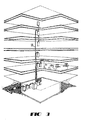
- the buffered optical fiber 20 includes an optical fiber 21 which typically includes a core and cladding designated together by the numeral 22 and a UV cured protective coating 23 about the core and cladding.
- the optical fiber 21 may include more than one protective coating. See U.S. patent 4,474,830.
- One commonly available coated optical fiber has an outer diameter of about 0.0254 cm.
- the buffered fiber 20 also includes a jacket 30 which is referred to as a buffer layer.
- the buffer layer 30 is made of a plastic buffering material such as polyvinyl chloride.
- the buffer layer 30 has a wall thickness in the range of about 0.0279 to 0.041 cm.
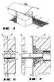
- This invention is directed to a buffered optical fiber which may be used in a riser cable 26 (see FIG. 3) and in a cable 27 to the home (see FIG. 4), for example, and in which controlled coupling exists between the buffer layer 30 and the underlying coating material.
- controlled coupling there is enhanced strippability of the buffer layer 30 or of the buffer layer and the underlying optical fiber coating material.
- the buffering layer and, if desired, the coating material easily removable, but they are easily removable without inflicting damage to the optical fiber.
- suitable adhesion exists between the buffer layer 30 and the underlying coating material to maintain the buffer layer in place during normal expected handling and use of the buffered optical fiber 20.
- Optical fibers must be stripped of the buffering layer 30 and in many instances of their coating materials to facilitate connectorization. In some instances, it is desirable to provide a transition between optical fiber cables and optical fiber ribbons. In this procedure, as disclosed in U.S. Patent 4,305,642, a substantial length of the covering of the cable is removed to expose buffered optical fibers, for example. This is done in order to be able to position a plurality of optical fibers on a tape and to enclose them in a second tape to form a ribbon and allow connectorization with an array type connector such as is shown in U.S. patent 3,864,018.
- the strippability of a reasonable length of the buffer layer 30 and the underlying optical fiber coating or coatings in a single operation for termination purposes, for example, is provided by interposing a decoupling material 40 between the coated optical fiber and the jacket (see FIGS. 1, 2 and 5).
- a decoupling material 40 should be one which facilitates the removal of a reasonable length of the buffer layer or buffer layer and coating material in one operation without causing damage to the optical fiber in the process of doing so.
- the material used as the decoupling material should not be compatible chemically with adjacent materials, so that they do not dissolve in either the coating material or in the buffering material. Such behavior would result in the loss of the interlayer between the coating material and the buffering material, which interlayer provides the desired controlled bonding.
- the decoupling material 40 may comprise a modified acrylic material such as an acrylate copolymer material, for example.
- the decoupling material is a composition which comprises an acrylate copolymer material available commercially as MODAFLOW® resin modifier from the Monsanto Company.
- the MODAFLOW® resin modifier is a high molecular weight, low volatility, complex polymeric viscous liquid.
- MODAFLOW® resin modifier is not water soluble, is soluble in Xylene, kerosene, isopropyl alcohol, petroleum ether and ether solvents and is virtually non-extractable.
- MODAFLOW® resin modifier is reported to be a copolymer blend of polyacrylates which is made from an acrylic acid and an alcohol to provide an ester which can be polymerized to make a resin.
- a polyacrylate is a thermoplastic resin made by the polymerization of an acrylic composition such as methyl methacrylate.
- Polymers of acrylic esters may be methyl, ethyl, butyl or 2-ethylhexyl.
- Such material of the preferred embodiment is reported to be an ethyl acrylate and 2-ethylhexyl acrylate copolymer or 2-propenoic acid ethyl ester, polymer with 2-propenoic acid, 2-ethylhexyl ester. Properties of this material are provided in an MSD brochure designated PC-1344 defoamer and in Technical Bulletin No. 1561 available from Monsanto.
- a solvent for processing, about 2.5% by weight of an acrylate copolymer material is blended with about 97.5% by weight of a solvent.
- the solvent is quick-drying and in the preferred embodiment, is acetone or an equivalent solvent. It is desired to include a fast-evaporating solvent which flashes off quickly.
- the composition of the decoupling material also may include a trace amount, for example about 0.05%, of an optical brightener.
- an optical brightener Such a constituent is useful during manufacture and in field use, for example, to verify that the buffered optical fiber includes a decoupling material. This is accomplished by exposing a length of the buffered optical fiber 20 to ultraviolet light (UV) energy such as from a UV lamp.
- UV ultraviolet light
- Such a decoupling material properly applied, provides sufficient adhesion to both the coating matrial and to the buffering material of the buffer layer 30. As a result, a completely unbonded buffer layer such as would result from the use of a release agent is avoided. At the same time, the adhesion is sufficiently low so that structural arrangements are possible where stripping of covering materials from the fiber may be accomplished readily.
- the decoupling material 40 is relatively thin.
- the decoupling material has a thickness in the range of 0.3 to 0.5 ⁇ m.
- a relatively thin layer of decoupling material there is mechanical interaction of portions of the buffer layer with portions of the underlying coating material thereby causing controlled coupling between the two. If too thin, there would be too much adhesion between the buffer layer 30 and the coating material and removal of the buffer layer would revert to the use of undesirable prior art techniques. On the other hand, if it is too thick, there would be complete separation of the buffer layer and the coating material and the buffer layer may slide relative to the coating material.
- inclusion of a solvent in the composition of the decoupling material facilitates the application of a relatively thin layer. By using a solvent, the solution of the decoupling material is diluted. Approximately 98% of the solution is evaporated thereby enabling the application of a thin layer.
- the buffered optical fiber 20 which includes the decoupling material 40 overcomes problems of the prior art. As will be recalled, in order to terminate an optical fiber it usually is necessary to remove the buffer layer 30 from an end portion and more likely than not also to remove the optical fiber coating material from at least a portion of the end portion.
- stripper blades 50-50 along an end portion 52 of a buffered optical fiber are caused to penetrate to a depth comprising the thickness of the buffer layer 30 plus a substantial portion of the coating thickness. Then the stripper blades 50-50 are caused to be moved to the right as viewed in FIG. 7. In the initial movement of the stripper blades 50-50 to the right, the buffer layer material of the end portion 52 tears or fractures from the buffer layer material of the remainder of the buffered optical fiber. The same action occurs with the coating material. Both the buffer layer and the coating materials then are free to be moved to the right.
- the coating material is compressed inside the buffer layer material, and the increasing volume of coating materials causes the buffer layer material to swell and, in some cases, split.
- the increased forces on the optical fiber of the end portion 52 caused by the compression of the coating material inside the buffering material during the stripping process generally are sufficient to cause the fiber to fracture.
- the forces exerted on the system are sufficient to cause failure of the low coupling forces that exist between the buffer layer 30 and the coating material because of the disposition of the thin layer 40 of interface decoupling material therebetween.
- the buffer layer is able to move slidably easily to the right.
- a gap forms between the buffer layer on the end portion and the blades 50-50, and the coating material spurts outwardly through the gap.
- the stripper blades 50-50 are repositioned 0.32 cm from the end of the buffer layer plastic and caused to penetrate only the buffer layer plastic. Relative motion between the stripper blades 50-50 and the buffered optical fiber with the blades so positioned causes another 0.32 cm of the buffer layer plastic to be removed.
- the buffered optical fiber 20 of this invention allows the removal of a reasonable length up to about two inches of the buffering and coating material in one operation, it also is especially useful when relatively long end portions of an optical fiber must be prepared for termination. Some of these may be as long as six inches.
- stripping of the buffering material or buffering material and coating was done in incremental steps. A craftsperson could have gone successfully through a number of steps only to break the fiber during the execution of the last step. Now, the entire end portion may be stripped with relative ease.
- the craftsperson assists manually the separation of the buffer layer on the end portion 52 from the remainder of the buffered optical fiber.
- the craftsperson grasps the buffer layer 30 on the end portion 52 and urges it toward the free end of the end portion. This is done because it would be difficult to cause the movement of the blades to cause the adhesion between the buffer layer and the underlying coating to fracture all the way to the end of the buffered fiber. Instead, manual assist is provided to remove the buffer layer. Afterwards, stripper blades are caused to penetrate the coating material and are moved to remove the coating material from the end portion.
- buffered optical fiber of this invention provides for the craftsperson and the designer. Almost any expected reasonable length may be stripped. Further, any combination of buffering material and coating material or buffering material alone may be removed as demanded to carry out a particular design termination.
- optical fiber cable of this invention is advantageous from the standpoint of connectorization. It may be terminated with a biconic connector which is disclosed in priorly mentioned U.S. patent 4,512,630. Also, it may be terminated by an ST® connector.
- the buffered optical fiber 20 of this invention also may be used to provide a multifiber cable.
- a cable may include a strength member system which may be metallic, for example, and which may be enclosed in a plastic material or which may include yarn such as KEVLAR® yarn, for example.
- Arranged within a core may be a plurality of the buffered optical fibers 20-20.
- the plurality of buffered optical fiber 20-20 are enclosed by a jacket which is made of a plastic material. For connectorization, a portion of the jacket is removed and each of the buffered single fibers which thus becomes exposed is stripped and terminated with a connector.
- the biconic and/or ST connector may be used to terminate each of the buffered optical fibers of the cable.
Landscapes
- Physics & Mathematics (AREA)
- General Physics & Mathematics (AREA)
- Optics & Photonics (AREA)
- Engineering & Computer Science (AREA)
- Civil Engineering (AREA)
- Structural Engineering (AREA)
- Chemical & Material Sciences (AREA)
- Chemical Kinetics & Catalysis (AREA)
- Health & Medical Sciences (AREA)
- Medicinal Chemistry (AREA)
- Polymers & Plastics (AREA)
- Organic Chemistry (AREA)
- Surface Treatment Of Glass Fibres Or Filaments (AREA)
- Light Guides In General And Applications Therefor (AREA)
- Optical Fibers, Optical Fiber Cores, And Optical Fiber Bundles (AREA)
- Vibration Dampers (AREA)
Applications Claiming Priority (2)
| Application Number | Priority Date | Filing Date | Title |
|---|---|---|---|
| US07/385,755 US5011260A (en) | 1989-07-26 | 1989-07-26 | Buffered optical fiber having a strippable buffer layer |
| US385755 | 1989-07-26 |
Publications (3)
| Publication Number | Publication Date |
|---|---|
| EP0410622A2 true EP0410622A2 (de) | 1991-01-30 |
| EP0410622A3 EP0410622A3 (en) | 1992-03-04 |
| EP0410622B1 EP0410622B1 (de) | 1996-10-23 |
Family
ID=23522747
Family Applications (1)
| Application Number | Title | Priority Date | Filing Date |
|---|---|---|---|
| EP90307779A Expired - Lifetime EP0410622B1 (de) | 1989-07-26 | 1990-07-17 | Mit einer abziehbaren Pufferschicht versehene optische Faser |
Country Status (10)
| Country | Link |
|---|---|
| US (1) | US5011260A (de) |
| EP (1) | EP0410622B1 (de) |
| JP (1) | JP2850919B2 (de) |
| KR (1) | KR910003410A (de) |
| CA (1) | CA2021515C (de) |
| DE (1) | DE69028958T2 (de) |
| DK (1) | DK0410622T3 (de) |
| ES (1) | ES2092494T3 (de) |
| MX (1) | MX166720B (de) |
| NO (1) | NO301096B1 (de) |
Cited By (19)
| Publication number | Priority date | Publication date | Assignee | Title |
|---|---|---|---|---|
| EP0545622A1 (de) * | 1991-11-29 | 1993-06-09 | BICC Public Limited Company | Nachrichtenkabel |
| US5381504A (en) * | 1993-11-15 | 1995-01-10 | Minnesota Mining And Manufacturing Company | Optical fiber element having a permanent protective coating with a Shore D hardness value of 65 or more |
| FR2768234A1 (fr) * | 1997-09-11 | 1999-03-12 | France Telecom | Structure de cables a fibres optiques autoresistantes a la compression |
| GB2359637A (en) * | 2000-02-23 | 2001-08-29 | Yazaki Corp | Coated plastics optical fibre |
| EP1910876A2 (de) * | 2005-08-04 | 2008-04-16 | Corning Cable Systems LLC | Mechanisch ablösbare beschichtete optische fasern |
| WO2009091243A1 (en) | 2008-01-18 | 2009-07-23 | Draka Comteq B.V. | Buffered optical fiber and telecommunications cable |
| WO2011116081A1 (en) * | 2010-03-16 | 2011-09-22 | Corning Cable Systems Llc | Fiber optic distribution network for multiple dwelling units |
| US8792767B2 (en) | 2010-04-16 | 2014-07-29 | Ccs Technology, Inc. | Distribution device |
| US8798427B2 (en) | 2007-09-05 | 2014-08-05 | Corning Cable Systems Llc | Fiber optic terminal assembly |
| US8879882B2 (en) | 2008-10-27 | 2014-11-04 | Corning Cable Systems Llc | Variably configurable and modular local convergence point |
| US8909019B2 (en) | 2012-10-11 | 2014-12-09 | Ccs Technology, Inc. | System comprising a plurality of distribution devices and distribution device |
| US9004778B2 (en) | 2012-06-29 | 2015-04-14 | Corning Cable Systems Llc | Indexable optical fiber connectors and optical fiber connector arrays |
| US9049500B2 (en) | 2012-08-31 | 2015-06-02 | Corning Cable Systems Llc | Fiber optic terminals, systems, and methods for network service management |
| US9219546B2 (en) | 2011-12-12 | 2015-12-22 | Corning Optical Communications LLC | Extremely high frequency (EHF) distributed antenna systems, and related components and methods |
| US9323020B2 (en) | 2008-10-09 | 2016-04-26 | Corning Cable Systems (Shanghai) Co. Ltd | Fiber optic terminal having adapter panel supporting both input and output fibers from an optical splitter |
| US9547144B2 (en) | 2010-03-16 | 2017-01-17 | Corning Optical Communications LLC | Fiber optic distribution network for multiple dwelling units |
| US9547145B2 (en) | 2010-10-19 | 2017-01-17 | Corning Optical Communications LLC | Local convergence point for multiple dwelling unit fiber optic distribution network |
| US10110307B2 (en) | 2012-03-02 | 2018-10-23 | Corning Optical Communications LLC | Optical network units (ONUs) for high bandwidth connectivity, and related components and methods |
| EP3347903B1 (de) * | 2015-09-10 | 2020-12-16 | Prysmian S.p.A. | Kabel mit faseroptischem sensor zur dehnungsmessung |
Families Citing this family (28)
| Publication number | Priority date | Publication date | Assignee | Title |
|---|---|---|---|---|
| GB2256604B (en) * | 1991-06-12 | 1995-04-19 | Northern Telecom Ltd | Plastics packaged optical fibre |
| US5181268A (en) * | 1991-08-12 | 1993-01-19 | Corning Incorporated | Strippable tight buffered optical waveguide fiber |
| US5373578A (en) * | 1993-12-21 | 1994-12-13 | At&T Corp. | Strippable coating for optical fiber |
| US5463706A (en) * | 1994-02-16 | 1995-10-31 | Thomas & Betts Corporation | Light traceable transmission conduit assembly |
| JP3462634B2 (ja) * | 1995-06-28 | 2003-11-05 | 住友電気工業株式会社 | 光ファイバ心線及びその被覆の除去方法 |
| US6415085B1 (en) * | 1995-08-01 | 2002-07-02 | At&T Corp. | Sub-miniature optical fiber cables, and apparatuses and methods for making the sub-miniature optical fiber cables |
| US5684910A (en) * | 1996-06-24 | 1997-11-04 | Lucent Technologies Inc. | Buffered optical fiber having a strippable buffer layer |
| JP3955333B2 (ja) | 1996-11-08 | 2007-08-08 | デーエスエム アイピー アセッツ ベー.ヴェー. | 放射線硬化性の光ガラスファイバー被覆用組成物、被覆光ガラスファイバー、及び光ガラスファイバーアセンブリー |
| US6130980A (en) * | 1997-05-06 | 2000-10-10 | Dsm N.V. | Ribbon assemblies and ink coating compositions for use in forming the ribbon assemblies |
| US6197422B1 (en) | 1997-05-06 | 2001-03-06 | Dsm, N.V. | Ribbon assemblies and radiation-curable ink compositions for use in forming the ribbon assemblies |
| US6085010A (en) * | 1997-06-11 | 2000-07-04 | Dsm N.V. | Optical glass fiber ribbon assemblies and radiation-curable compositions for use in forming ribbon assemblies |
| US6301415B1 (en) | 1997-08-14 | 2001-10-09 | Dsm N.V | Optical glass fiber ribbon assemblies, matrix forming compositions radiation-curable compositions |
| US6391936B1 (en) | 1997-12-22 | 2002-05-21 | Dsm N.V. | Radiation-curable oligomers radiation-curable compositions, coated optical glass fibers, and ribbon assemblies |
| US6110593A (en) | 1998-05-21 | 2000-08-29 | Dsm N.V. | Radiation-curable optical fiber primary coating system |
| US6040357A (en) * | 1998-05-28 | 2000-03-21 | Dsm N.V. | Method of making a radiation-curable ink composition, radiation-curable ink composition and ribbon assembly |
| US6215934B1 (en) | 1998-10-01 | 2001-04-10 | Lucent Technologies, Inc. | Coated optical fiber with improved strippability |
| US7403687B2 (en) | 2001-12-21 | 2008-07-22 | Pirelli Communications Cables And Systems Usa, Llc | Reinforced tight-buffered optical fiber and cables made with same |
| JPWO2003083546A1 (ja) * | 2002-03-29 | 2005-08-04 | 三菱電線工業株式会社 | 光ファイバ心線 |
| US6768853B2 (en) * | 2002-06-21 | 2004-07-27 | Fitel Usa Corp. | Buffered optical fibers and methods of making same |
| US6957000B2 (en) | 2002-10-31 | 2005-10-18 | Corning Cable Systems Llc | Peelable buffer layer having a preferential tear portion and methods of manufacturing the same |
| US20050135763A1 (en) * | 2003-12-17 | 2005-06-23 | Gary Drenzek | Optical fiber with a mechanically strippable coating and methods of making the same |
| US7142752B2 (en) * | 2004-04-30 | 2006-11-28 | Corning Cable Systems Llc | Buffered optical waveguides |
| US20050244113A1 (en) * | 2004-04-30 | 2005-11-03 | Chiasson David W | Buffered optical waveguides |
| JP4142002B2 (ja) * | 2004-11-19 | 2008-08-27 | 東日本電信電話株式会社 | 光ファイバ心線 |
| JP4847311B2 (ja) * | 2006-12-25 | 2011-12-28 | 株式会社東海理化電機製作所 | 車両用ミラー装置 |
| US20090274426A1 (en) * | 2008-04-30 | 2009-11-05 | Lail Jason C | Fiber optic cable and method of manufacturing the same |
| US9442264B1 (en) | 2014-12-23 | 2016-09-13 | Superior Essex International LP | Tight buffered optical fibers and optical fiber cables |
| US10031303B1 (en) | 2017-08-29 | 2018-07-24 | Superior Essex International LP | Methods for forming tight buffered optical fibers using compression to facilitate subsequent loosening |
Citations (3)
| Publication number | Priority date | Publication date | Assignee | Title |
|---|---|---|---|---|
| US4072400A (en) * | 1975-07-07 | 1978-02-07 | Corning Glass Works | Buffered optical waveguide fiber |
| JPS5833204A (ja) * | 1981-08-20 | 1983-02-26 | Fujitsu Ltd | 光伝送用フアイバ |
| JPS61126512A (ja) * | 1984-11-26 | 1986-06-14 | Nippon Telegr & Teleph Corp <Ntt> | 防水型光フアイバケ−ブル用充てん混和剤 |
Family Cites Families (10)
| Publication number | Priority date | Publication date | Assignee | Title |
|---|---|---|---|---|
| US3864018A (en) * | 1973-10-18 | 1975-02-04 | Bell Telephone Labor Inc | Method and means for splicing arrays of optical fibers |
| US4037922A (en) * | 1975-07-07 | 1977-07-26 | Corning Glass Works | Optical waveguide cable |
| GB1570624A (en) * | 1975-12-11 | 1980-07-02 | Western Electric Co | Optical fibre transmission arrangements |
| JPS52136642A (en) * | 1976-05-11 | 1977-11-15 | Sumitomo Electric Ind Ltd | Reinforced optical fiber |
| US4305642A (en) * | 1979-12-17 | 1981-12-15 | Western Electric Company, Inc. | Optical fiber transition device and assembly |
| DE3133274C2 (de) * | 1981-08-22 | 1986-09-25 | Messerschmitt-Bölkow-Blohm GmbH, 8000 München | Lichtleitkabel für fernlenkbare Flugkörper |
| US4474830A (en) * | 1982-12-29 | 1984-10-02 | At&T Bell Laboratories | Multiple coating of fibers |
| US4538881A (en) * | 1983-02-24 | 1985-09-03 | At&T Bell Laboratories | Optical fiber cable including a strain equalizing adhesive which constrains optical loss |
| JPS6345518U (de) * | 1986-09-11 | 1988-03-28 | ||
| US4729629A (en) * | 1987-02-26 | 1988-03-08 | Sumitomo Electric Research Triangle, Inc. | Bonded sheath cable with lubricant over seam |
-
1989
- 1989-07-26 US US07/385,755 patent/US5011260A/en not_active Expired - Lifetime
-
1990
- 1990-07-17 EP EP90307779A patent/EP0410622B1/de not_active Expired - Lifetime
- 1990-07-17 DK DK90307779.0T patent/DK0410622T3/da active
- 1990-07-17 DE DE69028958T patent/DE69028958T2/de not_active Expired - Fee Related
- 1990-07-17 ES ES90307779T patent/ES2092494T3/es not_active Expired - Lifetime
- 1990-07-19 CA CA002021515A patent/CA2021515C/en not_active Expired - Fee Related
- 1990-07-20 MX MX021673A patent/MX166720B/es unknown
- 1990-07-25 KR KR1019900011283A patent/KR910003410A/ko not_active Application Discontinuation
- 1990-07-25 NO NO903316A patent/NO301096B1/no unknown
- 1990-07-26 JP JP2196452A patent/JP2850919B2/ja not_active Expired - Fee Related
Patent Citations (3)
| Publication number | Priority date | Publication date | Assignee | Title |
|---|---|---|---|---|
| US4072400A (en) * | 1975-07-07 | 1978-02-07 | Corning Glass Works | Buffered optical waveguide fiber |
| JPS5833204A (ja) * | 1981-08-20 | 1983-02-26 | Fujitsu Ltd | 光伝送用フアイバ |
| JPS61126512A (ja) * | 1984-11-26 | 1986-06-14 | Nippon Telegr & Teleph Corp <Ntt> | 防水型光フアイバケ−ブル用充てん混和剤 |
Non-Patent Citations (1)
| Title |
|---|
| PATENT ABSTRACTS OF JAPAN vol. 10, no. 316 (P-510)(2372) 28 October 1986 & JP-A-61 126 512 ( NIPPON TELEGRAPH & TELEPHONE CORP ) 14 June 1986 * |
Cited By (28)
| Publication number | Priority date | Publication date | Assignee | Title |
|---|---|---|---|---|
| EP0545622A1 (de) * | 1991-11-29 | 1993-06-09 | BICC Public Limited Company | Nachrichtenkabel |
| US5381504A (en) * | 1993-11-15 | 1995-01-10 | Minnesota Mining And Manufacturing Company | Optical fiber element having a permanent protective coating with a Shore D hardness value of 65 or more |
| USRE36146E (en) * | 1993-11-15 | 1999-03-16 | Minnesota Mining And Manufacturing Company | Optical fiber element having a permanent protective coating with a shore D hardness value of 65 or more |
| FR2768234A1 (fr) * | 1997-09-11 | 1999-03-12 | France Telecom | Structure de cables a fibres optiques autoresistantes a la compression |
| EP0902310A1 (de) * | 1997-09-11 | 1999-03-17 | France Telecom Sa | Strukturen bei Faseroptischen Kabeln mit automatischem Kompressionswiderstand |
| US6067394A (en) * | 1997-09-11 | 2000-05-23 | France Telecom, S.A. | Structures of optical fiber cables self-reinforced against compression |
| GB2359637A (en) * | 2000-02-23 | 2001-08-29 | Yazaki Corp | Coated plastics optical fibre |
| EP1910876A2 (de) * | 2005-08-04 | 2008-04-16 | Corning Cable Systems LLC | Mechanisch ablösbare beschichtete optische fasern |
| EP1910876A4 (de) * | 2005-08-04 | 2009-11-25 | Corning Cable Sys Llc | Mechanisch ablösbare beschichtete optische fasern |
| US8798427B2 (en) | 2007-09-05 | 2014-08-05 | Corning Cable Systems Llc | Fiber optic terminal assembly |
| WO2009091243A1 (en) | 2008-01-18 | 2009-07-23 | Draka Comteq B.V. | Buffered optical fiber and telecommunications cable |
| EP2232318B1 (de) * | 2008-01-18 | 2014-03-12 | Draka Comteq B.V. | Gepufferte glasfaser und telekommunikationskabel damit |
| US9323020B2 (en) | 2008-10-09 | 2016-04-26 | Corning Cable Systems (Shanghai) Co. Ltd | Fiber optic terminal having adapter panel supporting both input and output fibers from an optical splitter |
| US8879882B2 (en) | 2008-10-27 | 2014-11-04 | Corning Cable Systems Llc | Variably configurable and modular local convergence point |
| WO2011116081A1 (en) * | 2010-03-16 | 2011-09-22 | Corning Cable Systems Llc | Fiber optic distribution network for multiple dwelling units |
| US9547144B2 (en) | 2010-03-16 | 2017-01-17 | Corning Optical Communications LLC | Fiber optic distribution network for multiple dwelling units |
| US8792767B2 (en) | 2010-04-16 | 2014-07-29 | Ccs Technology, Inc. | Distribution device |
| US9720197B2 (en) | 2010-10-19 | 2017-08-01 | Corning Optical Communications LLC | Transition box for multiple dwelling unit fiber optic distribution network |
| US9547145B2 (en) | 2010-10-19 | 2017-01-17 | Corning Optical Communications LLC | Local convergence point for multiple dwelling unit fiber optic distribution network |
| US9219546B2 (en) | 2011-12-12 | 2015-12-22 | Corning Optical Communications LLC | Extremely high frequency (EHF) distributed antenna systems, and related components and methods |
| US9602209B2 (en) | 2011-12-12 | 2017-03-21 | Corning Optical Communications LLC | Extremely high frequency (EHF) distributed antenna systems, and related components and methods |
| US9800339B2 (en) | 2011-12-12 | 2017-10-24 | Corning Optical Communications LLC | Extremely high frequency (EHF) distributed antenna systems, and related components and methods |
| US10110305B2 (en) | 2011-12-12 | 2018-10-23 | Corning Optical Communications LLC | Extremely high frequency (EHF) distributed antenna systems, and related components and methods |
| US10110307B2 (en) | 2012-03-02 | 2018-10-23 | Corning Optical Communications LLC | Optical network units (ONUs) for high bandwidth connectivity, and related components and methods |
| US9004778B2 (en) | 2012-06-29 | 2015-04-14 | Corning Cable Systems Llc | Indexable optical fiber connectors and optical fiber connector arrays |
| US9049500B2 (en) | 2012-08-31 | 2015-06-02 | Corning Cable Systems Llc | Fiber optic terminals, systems, and methods for network service management |
| US8909019B2 (en) | 2012-10-11 | 2014-12-09 | Ccs Technology, Inc. | System comprising a plurality of distribution devices and distribution device |
| EP3347903B1 (de) * | 2015-09-10 | 2020-12-16 | Prysmian S.p.A. | Kabel mit faseroptischem sensor zur dehnungsmessung |
Also Published As
| Publication number | Publication date |
|---|---|
| CA2021515A1 (en) | 1991-01-27 |
| DK0410622T3 (da) | 1996-11-18 |
| JP2850919B2 (ja) | 1999-01-27 |
| NO301096B1 (no) | 1997-09-08 |
| DE69028958D1 (de) | 1996-11-28 |
| EP0410622B1 (de) | 1996-10-23 |
| MX166720B (es) | 1993-01-29 |
| ES2092494T3 (es) | 1996-12-01 |
| KR910003410A (ko) | 1991-02-27 |
| NO903316L (no) | 1991-01-28 |
| JPH03102306A (ja) | 1991-04-26 |
| CA2021515C (en) | 1994-05-03 |
| EP0410622A3 (en) | 1992-03-04 |
| US5011260A (en) | 1991-04-30 |
| NO903316D0 (no) | 1990-07-25 |
| DE69028958T2 (de) | 1997-02-27 |
Similar Documents
| Publication | Publication Date | Title |
|---|---|---|
| EP0410622B1 (de) | Mit einer abziehbaren Pufferschicht versehene optische Faser | |
| US5684910A (en) | Buffered optical fiber having a strippable buffer layer | |
| EP0853248B1 (de) | Optische Faser mit Pufferschicht | |
| CA2662813C (en) | Spliced-on connector system and method, splicer, and connector holder for producing the same | |
| US9103995B2 (en) | Field terminable optical fiber connector with splice element | |
| US6839494B2 (en) | Dual stage fiber optic cable design | |
| US20190041588A1 (en) | Field installable optical fiber connector for fiber optic cables with rigid strength members | |
| US6295401B1 (en) | Optical fiber ribbon cables | |
| US20140037250A1 (en) | Field installed optical fiber connector for jacketed fiber cable and termination method | |
| GB2158603A (en) | Single mode optical fibre attenuators | |
| EP1895339A1 (de) | Optisches Kabel mit losen Hohladern | |
| EP2232318A1 (de) | Gepufferte glasfaser und telekommunikationskabel damit | |
| EP1376181B1 (de) | Optische Fasern mit Pufferschicht und zugehöriges Herstellungsverfahren | |
| US20160370543A1 (en) | Re-coated optical fibers and methods of re-coating optical fibers | |
| CA2933022A1 (en) | Branch distribution cable connectorization system | |
| EP3754397A1 (de) | Faseroptische verbinderanordnung mit crimphülsenunteranordnung und verfahren zur verwendung | |
| US20220252809A1 (en) | Optical fiber tape core wire, optical fiber cable, and method of manufacturing optical fiber tape core wire | |
| CN109541765B (zh) | 一种光纤及使用该光纤的光缆 | |
| WO2018137172A1 (en) | Field terminable optical fiber connector | |
| HASHIMOTO et al. | Pre-connectorized Ultra-High-Fiber-Count Cable for Easy Installation | |
| JP4144613B2 (ja) | 光ファイバ心線、それを用いた光ファイバテープユニットおよび光ファイバケーブル | |
| JP2004012811A (ja) | 外被付き光ファイバテープ心線 | |
| JP2005172978A (ja) | 光ファイバケーブル |
Legal Events
| Date | Code | Title | Description |
|---|---|---|---|
| PUAI | Public reference made under article 153(3) epc to a published international application that has entered the european phase |
Free format text: ORIGINAL CODE: 0009012 |
|
| AK | Designated contracting states |
Kind code of ref document: A2 Designated state(s): CH DE DK ES FR GB IT LI SE |
|
| PUAL | Search report despatched |
Free format text: ORIGINAL CODE: 0009013 |
|
| AK | Designated contracting states |
Kind code of ref document: A3 Designated state(s): CH DE DK ES FR GB IT LI SE |
|
| 17P | Request for examination filed |
Effective date: 19920821 |
|
| RAP3 | Party data changed (applicant data changed or rights of an application transferred) |
Owner name: AT&T CORP. |
|
| 17Q | First examination report despatched |
Effective date: 19940620 |
|
| GRAG | Despatch of communication of intention to grant |
Free format text: ORIGINAL CODE: EPIDOS AGRA |
|
| GRAH | Despatch of communication of intention to grant a patent |
Free format text: ORIGINAL CODE: EPIDOS IGRA |
|
| GRAH | Despatch of communication of intention to grant a patent |
Free format text: ORIGINAL CODE: EPIDOS IGRA |
|
| GRAA | (expected) grant |
Free format text: ORIGINAL CODE: 0009210 |
|
| AK | Designated contracting states |
Kind code of ref document: B1 Designated state(s): CH DE DK ES FR GB IT LI SE |
|
| ITF | It: translation for a ep patent filed |
Owner name: JACOBACCI & PERANI S.P.A. |
|
| ET | Fr: translation filed | ||
| REG | Reference to a national code |
Ref country code: DK Ref legal event code: T3 |
|
| REF | Corresponds to: |
Ref document number: 69028958 Country of ref document: DE Date of ref document: 19961128 |
|
| REG | Reference to a national code |
Ref country code: ES Ref legal event code: FG2A Ref document number: 2092494 Country of ref document: ES Kind code of ref document: T3 |
|
| REG | Reference to a national code |
Ref country code: CH Ref legal event code: NV Representative=s name: BOVARD AG PATENTANWAELTE |
|
| PLBE | No opposition filed within time limit |
Free format text: ORIGINAL CODE: 0009261 |
|
| STAA | Information on the status of an ep patent application or granted ep patent |
Free format text: STATUS: NO OPPOSITION FILED WITHIN TIME LIMIT |
|
| 26N | No opposition filed | ||
| PGFP | Annual fee paid to national office [announced via postgrant information from national office to epo] |
Ref country code: DK Payment date: 19980622 Year of fee payment: 9 |
|
| PGFP | Annual fee paid to national office [announced via postgrant information from national office to epo] |
Ref country code: SE Payment date: 19980624 Year of fee payment: 9 |
|
| PGFP | Annual fee paid to national office [announced via postgrant information from national office to epo] |
Ref country code: CH Payment date: 19980721 Year of fee payment: 9 |
|
| PGFP | Annual fee paid to national office [announced via postgrant information from national office to epo] |
Ref country code: ES Payment date: 19980722 Year of fee payment: 9 |
|
| PG25 | Lapsed in a contracting state [announced via postgrant information from national office to epo] |
Ref country code: ES Free format text: LAPSE BECAUSE OF NON-PAYMENT OF DUE FEES Effective date: 19990718 |
|
| PG25 | Lapsed in a contracting state [announced via postgrant information from national office to epo] |
Ref country code: SE Free format text: THE PATENT HAS BEEN ANNULLED BY A DECISION OF A NATIONAL AUTHORITY Effective date: 19990730 |
|
| PG25 | Lapsed in a contracting state [announced via postgrant information from national office to epo] |
Ref country code: LI Free format text: LAPSE BECAUSE OF NON-PAYMENT OF DUE FEES Effective date: 19990731 Ref country code: CH Free format text: LAPSE BECAUSE OF NON-PAYMENT OF DUE FEES Effective date: 19990731 |
|
| PG25 | Lapsed in a contracting state [announced via postgrant information from national office to epo] |
Ref country code: DK Free format text: LAPSE BECAUSE OF NON-PAYMENT OF DUE FEES Effective date: 19990802 |
|
| REG | Reference to a national code |
Ref country code: CH Ref legal event code: PL |
|
| REG | Reference to a national code |
Ref country code: DK Ref legal event code: EBP |
|
| EUG | Se: european patent has lapsed |
Ref document number: 90307779.0 |
|
| REG | Reference to a national code |
Ref country code: GB Ref legal event code: IF02 |
|
| PGFP | Annual fee paid to national office [announced via postgrant information from national office to epo] |
Ref country code: GB Payment date: 20030709 Year of fee payment: 14 |
|
| PGFP | Annual fee paid to national office [announced via postgrant information from national office to epo] |
Ref country code: FR Payment date: 20030718 Year of fee payment: 14 |
|
| PGFP | Annual fee paid to national office [announced via postgrant information from national office to epo] |
Ref country code: DE Payment date: 20030731 Year of fee payment: 14 |
|
| REG | Reference to a national code |
Ref country code: ES Ref legal event code: FD2A Effective date: 20000810 |
|
| PG25 | Lapsed in a contracting state [announced via postgrant information from national office to epo] |
Ref country code: GB Free format text: LAPSE BECAUSE OF NON-PAYMENT OF DUE FEES Effective date: 20040717 |
|
| PG25 | Lapsed in a contracting state [announced via postgrant information from national office to epo] |
Ref country code: DE Free format text: LAPSE BECAUSE OF NON-PAYMENT OF DUE FEES Effective date: 20050201 |
|
| GBPC | Gb: european patent ceased through non-payment of renewal fee |
Effective date: 20040717 |
|
| PG25 | Lapsed in a contracting state [announced via postgrant information from national office to epo] |
Ref country code: FR Free format text: LAPSE BECAUSE OF NON-PAYMENT OF DUE FEES Effective date: 20050331 |
|
| REG | Reference to a national code |
Ref country code: FR Ref legal event code: ST |
|
| PG25 | Lapsed in a contracting state [announced via postgrant information from national office to epo] |
Ref country code: IT Free format text: LAPSE BECAUSE OF NON-PAYMENT OF DUE FEES;WARNING: LAPSES OF ITALIAN PATENTS WITH EFFECTIVE DATE BEFORE 2007 MAY HAVE OCCURRED AT ANY TIME BEFORE 2007. THE CORRECT EFFECTIVE DATE MAY BE DIFFERENT FROM THE ONE RECORDED. Effective date: 20050717 |