EP0410342A2 - Einmesser-Reibahle - Google Patents
Einmesser-Reibahle Download PDFInfo
- Publication number
- EP0410342A2 EP0410342A2 EP90114066A EP90114066A EP0410342A2 EP 0410342 A2 EP0410342 A2 EP 0410342A2 EP 90114066 A EP90114066 A EP 90114066A EP 90114066 A EP90114066 A EP 90114066A EP 0410342 A2 EP0410342 A2 EP 0410342A2
- Authority
- EP
- European Patent Office
- Prior art keywords
- guide strips
- knife
- guide
- reamer
- titanium carbide
- Prior art date
- Legal status (The legal status is an assumption and is not a legal conclusion. Google has not performed a legal analysis and makes no representation as to the accuracy of the status listed.)
- Granted
Links
Images
Classifications
-
- B—PERFORMING OPERATIONS; TRANSPORTING
- B23—MACHINE TOOLS; METAL-WORKING NOT OTHERWISE PROVIDED FOR
- B23D—PLANING; SLOTTING; SHEARING; BROACHING; SAWING; FILING; SCRAPING; LIKE OPERATIONS FOR WORKING METAL BY REMOVING MATERIAL, NOT OTHERWISE PROVIDED FOR
- B23D77/00—Reaming tools
- B23D77/02—Reamers with inserted cutting edges
- B23D77/04—Reamers with inserted cutting edges with cutting edges adjustable to different diameters along the whole cutting length
- B23D77/048—Reamers with inserted cutting edges with cutting edges adjustable to different diameters along the whole cutting length by means of conical screw threads
-
- B—PERFORMING OPERATIONS; TRANSPORTING
- B23—MACHINE TOOLS; METAL-WORKING NOT OTHERWISE PROVIDED FOR
- B23D—PLANING; SLOTTING; SHEARING; BROACHING; SAWING; FILING; SCRAPING; LIKE OPERATIONS FOR WORKING METAL BY REMOVING MATERIAL, NOT OTHERWISE PROVIDED FOR
- B23D2277/00—Reaming tools
- B23D2277/20—Number of cutting edges
- B23D2277/201—One
-
- B—PERFORMING OPERATIONS; TRANSPORTING
- B23—MACHINE TOOLS; METAL-WORKING NOT OTHERWISE PROVIDED FOR
- B23D—PLANING; SLOTTING; SHEARING; BROACHING; SAWING; FILING; SCRAPING; LIKE OPERATIONS FOR WORKING METAL BY REMOVING MATERIAL, NOT OTHERWISE PROVIDED FOR
- B23D2277/00—Reaming tools
- B23D2277/46—Guiding pads
Definitions
- the invention relates to a one-knife reamer with a knife head having a knife plate and two guide strips.
- Single-edge reamers with a cutter head are known, in which a cutter plate is firmly clamped in a suitable manner, for example by means of a clamping claw.
- a first ceramic guide bar is provided on the circumference of the cutter head opposite the cutter plate and, seen in the direction of rotation, behind the cutter plate.
- emulsions are used for cooling or lubrication, which cool the cutting edge on the one hand, but also cool the lubrication on the other hand serve the guide rails.
- the disposal of the chips containing the coolant / lubricant is problematic, among other things due to the special lubricants used in the emulsion. Often, treatment as special waste is required. This means that the waste generated when processing surfaces requires special treatment for disposal, which is very cost-intensive.
- the guide strips made of the mixed ceramics mentioned here are also characterized by the fact that they are particularly insensitive to impacts but also to water. Since the ceramic is harder than hard metal, wear is reduced considerably, which also contributes to improving the service life of the guide strips and thus of the tool.
- a single-incision reamer with guide strips made of a mixed ceramic which contains portions of aluminum oxide and titanium carbide is particularly preferred, the titanium carbide portion preferably making up ⁇ 10%.
- Such guide strips are characterized by a particularly long service life.
- the surfaces of the guide strips are machined by grinding, preferably by diamond grinding, it is possible to machine bores in workpieces made of cast and non-ferrous metal without coolant. Dry machining is here half possible because less heat is absorbed by the guide rails and the tendency to weld is reduced.
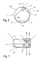
- FIG. 1 shows a side view of a single-cut reamer 1 with a cutter head 3 and an adjoining shaft 5.
- a cutter plate 7 is clamped in a suitable manner in the cutter head, here by means of a clamping claw 9, which is held by a clamping screw 11.
- the knife plate 7 can be adjusted radially with the aid of two adjusting members 13.
- the knife plate 7 is - seen in the direction of rotation shown by an arrow - a second guide bar 19, which is introduced into the outer wall of the knife head 3.
- the base body 23 of the knife head 3 is removed along a circular chord, so that a chip space 25 is used for chip removal.
- first guide bar 15 is arranged in a first groove 27 and the second guide bar 19 in a second groove 29.
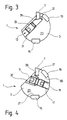
- the arrangement and structure of the setting members 13 can be seen more clearly from the cross section according to FIG. They have an adjusting screw 33 which is displaceably arranged in a bore 31 provided in the base body 23 and has an internal thread, and an adjusting wedge 35 which interacts with it.
- the essentially cylindrical adjusting wedge 35 which is also arranged in the bore 31, has a bevel on one side, which is in engagement with the underside of the knife plate 7 arranged in the groove 21. From FIG. 3 it can be seen that the knife plate 7 continues from the Circumferential line of the knife body 3 is pushed out when the set screw is screwed further into the bore 31, where by the adjusting wedge 35 in the direction of the knife plate 7.
- the clamping claw 9 is designed such that its surface 37 is flush with the outer surface of the cutter head 3 in the region of the chip space 25.
- the clamping claw 9 is supported with a clamping lip 39 on the front of the knife plate 7, so that the rear wall of the latter is pressed against a shoulder of the groove 21 and is thus held securely.
- the clamping claw 9 is held by the clamping screw 11 in the base body 23 of the cutter head, the clamping screw meshing on the one hand with an internal thread in the clamping claw 9 and on the other hand with an internal thread which is provided in a bore 41 in the base body 23 of the cutter head 3.
- the guide strips 17 and 19 are fastened in grooves 27 and 29 made in the cutter head by means of an adhesive. It is important to ensure that the bottom of the grooves is smooth and level so that the guide strips are supported as evenly as possible and do not break due to the forces generated when machining bores.
- the guide strips consist of highly compressed, hot isostatically pressed mixed ceramic, which is characterized in that it contains aluminum oxide and titanium carbide, a mixing ratio which contains less than 10% titanium carbide being preferred.
- the surfaces of such guide strips are characterized by a special low pore content, which means that they are practically pore-free. As a result, they have less tendency to weld than known ceramic guide rails or even hard metal guide rails, which means that the material of the machined bore wall does not settle as easily on the guide rails. It is therefore possible to dispense with coolants and lubricants when machining bores without the surface quality or dimensional accuracy of the bores produced being adversely affected. Post-processing times are also significantly reduced due to the reduced tendency to weld. The most important aspect, however, is that the chips generated when reworking surfaces can be easily disposed of. No post-treatment of the waste is required, since contamination from greases in the lubricant cannot occur, which have often forced the waste to be specially processed and stored.
- the surface of the guide strips has a radius of curvature which is somewhat smaller than that of the bore wall 17 to be machined.
- the surface of the guide strips is machined by grinding, in particular diamond grinding, so that a very smooth surface results, which is due to the special ceramic used here has particularly few pores or is practically pore-free.
- the surface quality is R Z ⁇ 1 ⁇ m, preferably ⁇ 0.5 ⁇ m.
- pores in the surface of the guide strips could be advantageous, for example for taking along and taking up coolants and lubricants.
- more and more emulsions are used that contain very little oil. This significantly reduced the lubrication properties and greatly reduced the service life of the guide strips and the tool.
- the guide strips used here have such a smooth surface that coolants and lubricants are hardly taken along. Nevertheless, such agents can be dispensed with, in particular when using diamond-ground cutting ceramics, for example when machining bores in workpieces made of cast and non-ferrous metal, without the surface quality or dimensional accuracy of the machined bore being adversely affected. As mentioned, the disposal of the resulting chips is considerably simplified.
- the thermal conductivity of the ceramic guide rails is significantly lower than that of hard metal guide rails. This results in thermal insulation, which leads to the tool body remaining cooler than with conventional reamers. The thermal stress on the tool is consequently reduced. The heat insulation is further promoted by the fact that the guide strips are preferably chosen thicker than is the case with hard metal strips. Due to the brittleness of the material, it was difficult to insert and fasten the guide rails in the grooves if the guide rails were too thin, because the rails would otherwise break easily.
Landscapes
- Engineering & Computer Science (AREA)
- Mechanical Engineering (AREA)
- Milling, Broaching, Filing, Reaming, And Others (AREA)
- Acyclic And Carbocyclic Compounds In Medicinal Compositions (AREA)
- Medicines Containing Plant Substances (AREA)
- Electronic Switches (AREA)
- Structures Of Non-Positive Displacement Pumps (AREA)
- Turbine Rotor Nozzle Sealing (AREA)
- Compositions Of Oxide Ceramics (AREA)
- Microwave Tubes (AREA)
- Earth Drilling (AREA)
- Magnetic Resonance Imaging Apparatus (AREA)
Abstract
Description
- Die Erfindung betrifft eine Einmesser-Reibahle mit einem eine Messerplatte und zwei Führungsleisten aufweisenden Messerkopf.
- Es sind Einschneiden-Reibahlen mit einem Messerkopf bekannt, in den auf geeignete Weise, beispielsweise mittels einer Spannpratze, eine Messerplatte fest eingespannt ist. Am Umfang des Messerkopfs sind gegenüber der Messerplatte eine erste und -in Drehrichtung gesehen- hinter der Messerplatte eine zweite Führungsleiste aus Keramik vorgesehen.
- Bei der Bearbeitung von Oberflächen mit Hilfe dieser bekannten Einmesser-Reibahlen werden zur Kühlung bzw. Schmierung Emulsionen eingesetzt, die einerseits der Kühlung der Schneide, andererseits auch der Kühlung aber insbesondere der Schmierung der Führungsleisten dienen. Die Entsorgung der mit dem Kühl-/Schmiermittel versetzten Späne ist, unter anderem aufgrund der verwendeten speziellen, der Emulsion beigesetzten Schmierstoffe, problematisch. Häufig bedarf es der Behandlung als Sondermüll. Das heißt, der bei der Bearbeitung von Oberflächen anfallende Abfall bedarf bei der Entsorgung einer besonderen Behandlung, die sehr kostenintensiv ist.
- Es ist daher Aufgabe der Erfindung, eine Einschneiden-Reibahle zu schaffen, bei der bei gleichbleibendem Verschleiß der Führungsleisten die beim Stand der Technik auftretenden Nachteile vermieden werden.
- Diese Aufgabe wird bei einer Einschneiden-Reibahle der eingangs genannten Art mit Hilfe der in Anspruch 1 genannten Merkmale gelöst. Die aus hoch verdichteter, heiß isostatisch gepreßter Mischkeramik bestehenden Führungsleisten zeichnen sich durch eine besonders porenarme Oberfläche aus. Überdies hat die Aluminiumoxid und Titankarbid enthaltende Keramik eine geringere Affinität zum Material der Bohrungswand, z.B. Guß oder Aluminium, als herkömmliche Materialien. Dadurch ist sichergestellt, daß sich -auch ohne Einsatz von fetthaltigen Kühl- bzw. Schmieremulsionen- Material der Wand der bearbeiteten Bohrung nicht an den Führungsleisten festsetzen und aufschweißen kann. Solche Aufschweißungen würden auch eine Bearbeitung bzw. einen Austausch der Führungsleisten erzwingen, das heißt, die Standzeit des Werkzeugs reduzieren. Die anfallenden Späne können wegen der Trockenbearbeitung der Oberflächen ohne besondere Reinigungsverfahren und ohne die teilweise aufwendige Rückgewinnung von Kühl- bzw. Schmiermitteln entsorgt werden.
- Die aus der hier angesprochenen Mischkeramik bestehenden Führungsleisten zeichnen sich überdies dadurch aus, daß sie besonders unempfindlich gegenüber Stößen aber auch gegen Wasser sind. Da die Keramik härter als Hartmetall ist, wird der Verschleiß sehr stark reduziert, was ebenfalls zur Verbesserung der Lebensdauer der Führungsleisten und damit des Werkzeugs beiträgt.
- Besonders bevorzugt wird eine Einschneiden-Reibahle mit Führungsleisten aus einer Mischkeramik, die Anteile von Aluminiumoxid und Titankarbid enthält, wobei der Titankarbidanteil vorzugsweise ≦ 10 % ausmacht. Derartige Führungsleisten zeichnen sich durch eine besonders hohe Standzeit aus.
- Schließlich wird eine Weiterbildung einer Einschneiden-Reibahle bevorzugt, bei der die Führungsleisten mittels Klebstoff in im Messerkopf vorgesehenen Nuten befestigt sind. Eine derartige Anbringung der Führungsleisten ist damit relativ einfach und preiswert.
- Wenn die Oberflächen der Führungsleisten durch Schleifen, vorzugsweise durch Diamantschleifen bearbeitet werden, ist es möglich, auch Bohrungen in Werkstücken aus Guß- und Buntmetall ohne Kühlmittel zu bearbeiten. Die Trockenbearbeitung ist hier des halb möglich, weil weniger Wärme über die Führungsleisten aufgenommen und dadurch die Aufschweißneigung vermindert wird.
- Die Erfindung wird im folgenden anhand der ein Ausführungsbeispiel wiedergebenden Zeichnung näher erläutert. Es zeigen:
- Figur 1 eine Seitenansicht einer Einschneiden-Reibahle;
- Figur 2 eine Vorderansicht einer Einschneiden-Reibahle gemäß Figur 1;
- Figur 3 einen Querschnitt entlang der in Figur 1 eingezeichneten Linie III-III und
- Figur 4 einen Querschnitt durch die in Figur 1 dargestellte Reibahle entlang der Linie IV-IV.
- Figur 1 zeigt eine Seitenansicht einer Einschneiden-Reibahle 1 mit einem Messerkopf 3 und einem sich daran anschließenden Schaft 5. In dem Messerkopf ist eine Messerplatte 7 auf geeignete Weise festgespannt, hier mittels einer Spannpratze 9, die von einer Spannschraube 11 gehalten wird. Die Messerplatte 7 ist radial einstellbar und zwar mit Hilfe zweier Einstellglieder 13. Am Umfang des Messerkopfs 3 befindet sich eine erste Führungsleiste 15, die der Messerplatte 7 gegenüberliegt.
- In der Vorderansicht gemäß Figur 2 sind gleiche Teile mit gleichen Bezugszeichen versehen. Bei die ser Darstellung ist zusätzlich die Umfangslinie 17 einer zu bearbeitenden Bohrung eingezeichnet.
- Der Messerplatte 7 ist -in der durch einen Pfeil dargestellten Drehrichtung gesehen- eine zweite Führungsleiste 19 nachgeordnet, die in die Außenwand des Messerkopfs 3 eingebracht ist.
- Auf der Vorderseite der in einer Nut 21 liegenden Messerplatte ist der Grundkörper 23 des Messerkopfs 3 entlang einer Kreissehne abgetragen, so daß ein der Spanabfuhr dienender Spanraum 25 entsteht.
- Aus der Darstellung ist erkennbar, daß die erste Führungsleiste 15 in einer ersten Nut 27 und die zweite Führungsleite 19 in einer zweiten Nut 29 angeordnet sind.
- Aus dem Querschnitt gemäß Figur 3 sind die Anordnung und der Aufbau der Einstellglieder 13 genauer ersichtlich. Sie weisen eine in einer in den Grundkörper 23 eingebrachten, mit einem Innengewinde versehenen Bohrung 31 verschiebbar angeordnete Stellschraube 33 sowie einen mit dieser zusammenwirkenden Stellkeil 35 auf. Der ebenfalls in der Bohrung 31 angeordnete, im wesentlichen zylindrische Stellkeil 35 weist auf einer Seite eine Abschrägung auf, die in Eingriff steht mit der Unterseite der in der Nut 21 angeordneten Messerplatte 7. Aus Figur 3 ist ersichtlich, daß die Messerplatte 7 weiter aus der Umfangslinie des Messerkörpers 3 herausgeschoben wird, wenn die Stellschraube weiter in die Bohrung 31 hineingeschraubt wird, wo durch der Stellkeil 35 weiter in Richtung auf die Messerplatte 7 verschoben wird.
- Aus dem Querschnitt gemäß Figur 4 ist ersichtlich, daß die Spannpratze 9 so ausgebildet ist, daß ihre Oberfläche 37 mit der Außenfläche des Messerkopfs 3 im Bereich des Spanraums 25 fluchtet. Die Spannpratze 9 stützt sich mit einer Spannlippe 39 auf der Vorderseite der Messerplatte 7 ab, so daß diese mit ihrer Rückwand gegen eine Schulter der Nut 21 gepreßt und so sicher gehalten wird.
- Die Spannpratze 9 wird durch die Spannschraube 11 im Grundkörper 23 des Messerkopfs gehalten, wobei die Spannschraube einerseits mit einem Innengewinde in der Spannpratze 9 und andererseits mit einem Innengewinde kämmt, das in einer Bohrung 41 im Grundkörper 23 des Messerkopfs 3 vorgesehen ist.
- Die Führungsleisten 17 und 19 sind in im Messerkopf eingebrachten Nuten 27 und 29 mittels eines Klebstoffs befestigt. Es ist darauf zu achten, daß der Boden der Nuten glatt und eben ist, damit die Führungsleisten möglichst gleichmäßig abgestützt werden und nicht aufgrund der bei der Bearbeitung von Bohrungen entstehenden Kräfte zerbrechen.
- Die Führungsleisten bestehen aus hoch verdichteter, heiß isostatisch gepreßter Mischkeramik, die sich dadurch auszeichnet, daß sie Aluminiumoxid und Titankarbid enthält, wobei ein Mischungsverhältnis bevorzugt wird, das weniger als 10 % Titankarbid enthält.
- Die Oberflächen derartiger Führungsleisten zeichnen sich durch eine besondere Porenarmut aus, das heißt, sie sind praktisch porenfrei. Dadurch haben sie weit weniger als bekannte Keramik-Führungsleisten oder gar Hartmetall-Führungsleisten die Tendenz zum Aufschweißen, das heißt, Material der bearbeiteten Bohrungswand setzt sich nicht so leicht auf den Führungsleisten ab. Daher kann bei der Bearbeitung von Bohrungen auf Kühl- und Schmiermittel verzichtet werden, ohne daß die Oberflächenqualität oder Maßhaltigkeit der hergestellten Bohrungen nachteilig beeinflußt würde. Auch werden aufgrund der reduzierten Aufschweißneigung Nachbearbeitungszeiten deutlich reduziert. Der wesentlichste Gesichtspunkt ist jedoch, daß die bei der Überarbeitung von Oberflächen anfallenden Späne ohne weiteres entsorgt werden können. Es bedarf keinerlei Nachbehandlung des anfallenden Abfalls, da Verunreinigungen durch im Schmiermittel vorhandene Fette nicht auftreten können, die häufig eine besondere Aufarbeitung und Lagerung des Abfalls erzwungen haben.
- Die Oberfläche der Führungsleisten weist einen Krümmungsradius auf, der etwas kleiner ist als der der zu bearbeitenden Bohrungswandung 17. Die Oberfläche der Führungsleisten ist durch Schleifen, insbesondere durch Diamantschleifen bearbeitet, so daß sich eine sehr glatte Oberfläche ergibt, die aufgrund der hier verwendeten speziellen Keramik besonders wenig Poren aufweist bzw. praktisch porenfrei ist. Es ergibt sich eine Oberflächengüte von RZ < 1µm vorzugsweise von < 0,5 µm.
- Grundsätzlich wurde davon ausgegangen, daß Poren in der Oberflache der Führungsleisten von Vorteil sein könnten, beispielsweise zur Mitnahme und Aufnahme von Kühl- und Schmiermitteln. Aus Gründen des Umweltschutzes werden mehr und mehr Emulsionen verwendet, die sehr wenig Öl enthalten. Dadurch wurden die Schmierungseigenschaften wesentlich verringert und die Standzeit der Führungsleisten bzw. des Werkzeugs stark verkürzt.
- Die hier verwendeten Führungsleisten haben eine derartig glatte Oberfläche, daß Kühl- und Schmiermittel kaum noch mitgenommen werden. Dennoch kann, insbesondere beim Einsatz von diamantgeschliffener Schneidkeramik, beispielsweise bei der Bearbeitung von Bohrungen in Werkstücken aus Guß- und Buntmetall auf derartige Mittel verzichtet werden, ohne daß die Oberflächengüte oder Maßhaltigkeit der bearbeiteten Bohrung nachteilig beeinflußt würde. Damit wird die Entsorgung der anfallenden Späne, wie gesagt, wesentlich vereinfacht.
- Durch den Einsatz der hier beschriebenen Keramik-Führungsleisten ergibt sich noch einer weitere Ersparnis dadurch, daß auf Kühl- und Schmiermittel bei der Bearbeitung von Bohrungen verzichtet werden kann.
- Die Wärmeleitfähigkeit der Keramik-Führungsleisten ist wesentlich geringer als die von Hartmetall-Führungsleisten. Dadurch findet eine Wärmeisolation statt, die dazu führt, daß der Werkzeugkörper kühler bleibt als bei herkömmlichen Reibahlen. Die thermische Belastung des Werkzeugs wird folglich reduziert. Die Wärmeisolation wird noch dadurch gefördert, daß die Führungsleisten vorzugsweise dikker gewählt werden als dies bei Hartmetalleisten der Fall ist. Aufgrund der Sprödigkeit des Materials wurde bei zu dünnen Führungsleisten das Einbringen und Befestigen der Führungsleisten in den Nuten erschwert, weil die Leisten sonst leicht brechen.
Claims (4)
Priority Applications (1)
| Application Number | Priority Date | Filing Date | Title |
|---|---|---|---|
| AT90114066T ATE90246T1 (de) | 1989-07-28 | 1990-07-23 | Einmesser-reibahle. |
Applications Claiming Priority (2)
| Application Number | Priority Date | Filing Date | Title |
|---|---|---|---|
| DE3924998A DE3924998A1 (de) | 1989-07-28 | 1989-07-28 | Einmesser-reibahle |
| DE3924998 | 1989-07-28 |
Publications (3)
| Publication Number | Publication Date |
|---|---|
| EP0410342A2 true EP0410342A2 (de) | 1991-01-30 |
| EP0410342A3 EP0410342A3 (en) | 1991-06-05 |
| EP0410342B1 EP0410342B1 (de) | 1993-06-09 |
Family
ID=6386030
Family Applications (1)
| Application Number | Title | Priority Date | Filing Date |
|---|---|---|---|
| EP90114066A Expired - Lifetime EP0410342B1 (de) | 1989-07-28 | 1990-07-23 | Einmesser-Reibahle |
Country Status (6)
| Country | Link |
|---|---|
| EP (1) | EP0410342B1 (de) |
| AT (1) | ATE90246T1 (de) |
| DD (1) | DD296628A5 (de) |
| DE (2) | DE3924998A1 (de) |
| DK (1) | DK0410342T3 (de) |
| ES (1) | ES2044338T3 (de) |
Cited By (4)
| Publication number | Priority date | Publication date | Assignee | Title |
|---|---|---|---|---|
| EP0558811A1 (de) * | 1992-01-31 | 1993-09-08 | MAPAL Fabrik für Präzisionswerkzeuge Dr. Kress KG | Einmesser-Reibahle |
| EP0713747A1 (de) * | 1994-11-23 | 1996-05-29 | August Beck GmbH & Co. | Verfahren zur Herstellung von Rohlingen für Führungsleisten für Einschneiden-Reibahlen und zum Finishen von Einschneiden-Reibahlen |
| US5921727A (en) * | 1998-01-20 | 1999-07-13 | Cogsdill Tool Products, Inc. | Reamer with friction resistant layer and method for forming same |
| WO2005107987A1 (de) * | 2004-05-04 | 2005-11-17 | MAPAL Fabrik für Präzisionswerkzeuge Dr. Kress KG | Messerplatte und reibahle |
Families Citing this family (6)
| Publication number | Priority date | Publication date | Assignee | Title |
|---|---|---|---|---|
| DE4329553C2 (de) * | 1993-09-02 | 1997-12-18 | Beck August Gmbh Co | Einmesser-Reibahle |
| DE4405750C2 (de) † | 1994-02-23 | 1997-04-30 | Mapal Fab Praezision | Reibahle mit mindestens einer Messerplatte, die auf ihrer Vorderseite mit einer im wesentlichen V-förmigen Spannkerbe versehen ist |
| DE19518241C2 (de) * | 1995-05-15 | 1998-07-16 | Mapal Fab Praezision | Reibahle |
| DE19746462C1 (de) * | 1997-10-21 | 1999-04-01 | Itw E V | Verfahren zur Herstellung einer Einschneiden-Reibahle und dergleichen |
| DE102005034422B4 (de) * | 2005-07-13 | 2008-10-23 | MAPAL Fabrik für Präzisionswerkzeuge Dr. Kress KG | Reibahle und Verfahren zu deren Herstellung |
| DE102009042951B3 (de) * | 2009-09-24 | 2011-03-03 | Hans Langesee Ges.M.B.H. | Reibahle und deren Verwendung |
Family Cites Families (5)
| Publication number | Priority date | Publication date | Assignee | Title |
|---|---|---|---|---|
| US2977829A (en) * | 1955-03-03 | 1961-04-04 | Masch Und Prazisionswerkzeugf | Machine reamer |
| DE1477708A1 (de) * | 1962-04-12 | 1969-07-24 | Sandco Ltd | Spanabhebend arbeitender Drehbohrer |
| DE2939134A1 (de) * | 1978-10-02 | 1980-04-17 | Keramik Wtb Veb | Verfahren und vorrichtung zum isostatischen pressen von keramischen gegenstaenden |
| DE3151413A1 (de) * | 1981-12-24 | 1983-07-14 | MTU Motoren- und Turbinen-Union München GmbH, 8000 München | "schaufel einer stroemungsmaschine, insbesondere gasturbine" |
| JPS60204687A (ja) * | 1984-03-30 | 1985-10-16 | 三菱マテリアル株式会社 | 表面被覆窒化珪素基セラミック工具部材 |
-
1989
- 1989-07-28 DE DE3924998A patent/DE3924998A1/de active Granted
-
1990
- 1990-07-23 ES ES90114066T patent/ES2044338T3/es not_active Expired - Lifetime
- 1990-07-23 DK DK90114066.5T patent/DK0410342T3/da active
- 1990-07-23 EP EP90114066A patent/EP0410342B1/de not_active Expired - Lifetime
- 1990-07-23 AT AT90114066T patent/ATE90246T1/de not_active IP Right Cessation
- 1990-07-23 DE DE9090114066T patent/DE59001680D1/de not_active Expired - Fee Related
- 1990-07-27 DD DD90343112A patent/DD296628A5/de not_active IP Right Cessation
Cited By (5)
| Publication number | Priority date | Publication date | Assignee | Title |
|---|---|---|---|---|
| EP0558811A1 (de) * | 1992-01-31 | 1993-09-08 | MAPAL Fabrik für Präzisionswerkzeuge Dr. Kress KG | Einmesser-Reibahle |
| US5328304A (en) * | 1992-01-31 | 1994-07-12 | Mapal Fabrik Fur Prazisionswerkzeuge Dr. Kress Kg | Reamer |
| EP0713747A1 (de) * | 1994-11-23 | 1996-05-29 | August Beck GmbH & Co. | Verfahren zur Herstellung von Rohlingen für Führungsleisten für Einschneiden-Reibahlen und zum Finishen von Einschneiden-Reibahlen |
| US5921727A (en) * | 1998-01-20 | 1999-07-13 | Cogsdill Tool Products, Inc. | Reamer with friction resistant layer and method for forming same |
| WO2005107987A1 (de) * | 2004-05-04 | 2005-11-17 | MAPAL Fabrik für Präzisionswerkzeuge Dr. Kress KG | Messerplatte und reibahle |
Also Published As
| Publication number | Publication date |
|---|---|
| DE3924998A1 (de) | 1991-02-07 |
| ES2044338T3 (es) | 1994-01-01 |
| EP0410342B1 (de) | 1993-06-09 |
| EP0410342A3 (en) | 1991-06-05 |
| DE3924998C2 (de) | 1992-08-27 |
| DD296628A5 (de) | 1991-12-12 |
| ATE90246T1 (de) | 1993-06-15 |
| DK0410342T3 (da) | 1993-11-15 |
| DE59001680D1 (de) | 1993-07-15 |
Similar Documents
| Publication | Publication Date | Title |
|---|---|---|
| EP1317985B1 (de) | Werkzeug zur Feinstbearbeitung von Oberflächen | |
| DE69930449T3 (de) | Drehendes Schneidwerkzeug mit Wendeschneideinsatz | |
| EP2670550B1 (de) | Bohrwerkzeug und verfahren zur herstellung von bohrungen | |
| EP1511590B1 (de) | Fräser mit wiper-radius | |
| AT410188B (de) | Schneidwerkzeug und wendeschneidplatte | |
| EP0410342B1 (de) | Einmesser-Reibahle | |
| DE202015009493U1 (de) | Schneidplatte und Schneidwerkzeug | |
| EP0485546B1 (de) | Schneideinsatz für werkzeuge | |
| EP1901873A1 (de) | Verfahren zur zerspanenden bearbeitung von kurbelwellen und vorrichtung zur durchführung dieses verfahrens | |
| DD272618A1 (de) | Drehwerkzeuge zur aussenbearbeitung rotationssymmetrischer werkstuecke | |
| DE29603475U1 (de) | Bohrwerkzeug | |
| EP0264599B1 (de) | Aufbohrwerkzeug | |
| DE102004008166A1 (de) | Werkzeug zur spanenden Bearbeitung von Präzisionsbohrungen | |
| DE4408335C2 (de) | Entgratungswerkzeug | |
| DE69407589T2 (de) | Einstellbares schneidwerkzeug für schälbearbeitung | |
| AT389831B (de) | Werkzeug zum bearbeiten von bohrungen | |
| DE2510653C2 (de) | Fräswerkzeug mit in Kassetten angeordneten Wendeschneidplatten | |
| DE3504296A1 (de) | Drehmaschinenwerkzeug mit einem schaft als traegermaterial fuer den eigentlichen, die zerspanung vornehmenden drehmeissel | |
| EP0884125A3 (de) | Reibahle | |
| DE20221097U1 (de) | Fräser mit Wiper-Radius | |
| DE4012243A1 (de) | Einmesser-reibahle | |
| DE8627969U1 (de) | Gewindebohrer | |
| DE29603473U1 (de) | Stufenbohrer | |
| DE29607213U1 (de) | Mehrbereichs Fasensenker mit Wendeschneidplatte zur Kantenbearbeitung an Bohrungen | |
| DE3233856A1 (de) | Schleifwerkzeug, insbesondere honwerkzeug |
Legal Events
| Date | Code | Title | Description |
|---|---|---|---|
| PUAI | Public reference made under article 153(3) epc to a published international application that has entered the european phase |
Free format text: ORIGINAL CODE: 0009012 |
|
| AK | Designated contracting states |
Kind code of ref document: A2 Designated state(s): AT BE CH DE DK ES FR GB IT LI NL SE |
|
| PUAL | Search report despatched |
Free format text: ORIGINAL CODE: 0009013 |
|
| AK | Designated contracting states |
Kind code of ref document: A3 Designated state(s): AT BE CH DE DK ES FR GB IT LI NL SE |
|
| 17P | Request for examination filed |
Effective date: 19911109 |
|
| 17Q | First examination report despatched |
Effective date: 19921119 |
|
| GRAA | (expected) grant |
Free format text: ORIGINAL CODE: 0009210 |
|
| AK | Designated contracting states |
Kind code of ref document: B1 Designated state(s): AT BE CH DE DK ES FR GB IT LI NL SE |
|
| REF | Corresponds to: |
Ref document number: 90246 Country of ref document: AT Date of ref document: 19930615 Kind code of ref document: T |
|
| REF | Corresponds to: |
Ref document number: 59001680 Country of ref document: DE Date of ref document: 19930715 |
|
| ET | Fr: translation filed | ||
| ITF | It: translation for a ep patent filed | ||
| GBT | Gb: translation of ep patent filed (gb section 77(6)(a)/1977) |
Effective date: 19930826 |
|
| REG | Reference to a national code |
Ref country code: DK Ref legal event code: T3 |
|
| REG | Reference to a national code |
Ref country code: ES Ref legal event code: FG2A Ref document number: 2044338 Country of ref document: ES Kind code of ref document: T3 |
|
| PLBE | No opposition filed within time limit |
Free format text: ORIGINAL CODE: 0009261 |
|
| STAA | Information on the status of an ep patent application or granted ep patent |
Free format text: STATUS: NO OPPOSITION FILED WITHIN TIME LIMIT |
|
| 26N | No opposition filed | ||
| PGFP | Annual fee paid to national office [announced via postgrant information from national office to epo] |
Ref country code: FR Payment date: 19940609 Year of fee payment: 5 |
|
| PGFP | Annual fee paid to national office [announced via postgrant information from national office to epo] |
Ref country code: AT Payment date: 19940614 Year of fee payment: 5 |
|
| PGFP | Annual fee paid to national office [announced via postgrant information from national office to epo] |
Ref country code: SE Payment date: 19940615 Year of fee payment: 5 |
|
| PGFP | Annual fee paid to national office [announced via postgrant information from national office to epo] |
Ref country code: GB Payment date: 19940620 Year of fee payment: 5 |
|
| PGFP | Annual fee paid to national office [announced via postgrant information from national office to epo] |
Ref country code: CH Payment date: 19940627 Year of fee payment: 5 |
|
| PGFP | Annual fee paid to national office [announced via postgrant information from national office to epo] |
Ref country code: DK Payment date: 19940630 Year of fee payment: 5 |
|
| PGFP | Annual fee paid to national office [announced via postgrant information from national office to epo] |
Ref country code: BE Payment date: 19940705 Year of fee payment: 5 |
|
| PGFP | Annual fee paid to national office [announced via postgrant information from national office to epo] |
Ref country code: ES Payment date: 19940706 Year of fee payment: 5 |
|
| PGFP | Annual fee paid to national office [announced via postgrant information from national office to epo] |
Ref country code: NL Payment date: 19940731 Year of fee payment: 5 |
|
| EAL | Se: european patent in force in sweden |
Ref document number: 90114066.5 |
|
| PG25 | Lapsed in a contracting state [announced via postgrant information from national office to epo] |
Ref country code: GB Effective date: 19950723 Ref country code: DK Effective date: 19950723 Ref country code: AT Effective date: 19950723 |
|
| REG | Reference to a national code |
Ref country code: DK Ref legal event code: EBP |
|
| PG25 | Lapsed in a contracting state [announced via postgrant information from national office to epo] |
Ref country code: SE Effective date: 19950724 Ref country code: ES Free format text: LAPSE BECAUSE OF THE APPLICANT RENOUNCES Effective date: 19950724 |
|
| PG25 | Lapsed in a contracting state [announced via postgrant information from national office to epo] |
Ref country code: BE Effective date: 19950731 Ref country code: LI Effective date: 19950731 Ref country code: CH Effective date: 19950731 |
|
| BERE | Be: lapsed |
Owner name: MAPAL FABRIK FUR PRAZISIONSWERKZEUGE DR. KRESS K. Effective date: 19950731 |
|
| PG25 | Lapsed in a contracting state [announced via postgrant information from national office to epo] |
Ref country code: NL Effective date: 19960201 |
|
| REG | Reference to a national code |
Ref country code: CH Ref legal event code: PL |
|
| GBPC | Gb: european patent ceased through non-payment of renewal fee |
Effective date: 19950723 |
|
| NLV4 | Nl: lapsed or anulled due to non-payment of the annual fee |
Effective date: 19960201 |
|
| EUG | Se: european patent has lapsed |
Ref document number: 90114066.5 |
|
| PG25 | Lapsed in a contracting state [announced via postgrant information from national office to epo] |
Ref country code: FR Effective date: 19960430 |
|
| REG | Reference to a national code |
Ref country code: FR Ref legal event code: ST |
|
| REG | Reference to a national code |
Ref country code: FR Ref legal event code: ST |
|
| REG | Reference to a national code |
Ref country code: FR Ref legal event code: ST |
|
| REG | Reference to a national code |
Ref country code: ES Ref legal event code: FD2A Effective date: 19991102 |
|
| PG25 | Lapsed in a contracting state [announced via postgrant information from national office to epo] |
Ref country code: IT Free format text: LAPSE BECAUSE OF NON-PAYMENT OF DUE FEES;WARNING: LAPSES OF ITALIAN PATENTS WITH EFFECTIVE DATE BEFORE 2007 MAY HAVE OCCURRED AT ANY TIME BEFORE 2007. THE CORRECT EFFECTIVE DATE MAY BE DIFFERENT FROM THE ONE RECORDED. Effective date: 20050723 |
|
| PGFP | Annual fee paid to national office [announced via postgrant information from national office to epo] |
Ref country code: DE Payment date: 20080726 Year of fee payment: 19 |
|
| PG25 | Lapsed in a contracting state [announced via postgrant information from national office to epo] |
Ref country code: DE Free format text: LAPSE BECAUSE OF NON-PAYMENT OF DUE FEES Effective date: 20100202 |