EP0407768B1 - Vollhydraulische Servolenkeinrichtung - Google Patents
Vollhydraulische Servolenkeinrichtung Download PDFInfo
- Publication number
- EP0407768B1 EP0407768B1 EP90111582A EP90111582A EP0407768B1 EP 0407768 B1 EP0407768 B1 EP 0407768B1 EP 90111582 A EP90111582 A EP 90111582A EP 90111582 A EP90111582 A EP 90111582A EP 0407768 B1 EP0407768 B1 EP 0407768B1
- Authority
- EP
- European Patent Office
- Prior art keywords
- hydraulic pressure
- steering unit
- steering apparatus
- power steering
- hydraulic
- Prior art date
- Legal status (The legal status is an assumption and is not a legal conclusion. Google has not performed a legal analysis and makes no representation as to the accuracy of the status listed.)
- Expired - Lifetime
Links
Images


Classifications
-
- B—PERFORMING OPERATIONS; TRANSPORTING
- B62—LAND VEHICLES FOR TRAVELLING OTHERWISE THAN ON RAILS
- B62D—MOTOR VEHICLES; TRAILERS
- B62D5/00—Power-assisted or power-driven steering
- B62D5/06—Power-assisted or power-driven steering fluid, i.e. using a pressurised fluid for most or all the force required for steering a vehicle
- B62D5/09—Power-assisted or power-driven steering fluid, i.e. using a pressurised fluid for most or all the force required for steering a vehicle characterised by means for actuating valves
- B62D5/093—Telemotor driven by steering wheel movement
- B62D5/097—Telemotor driven by steering wheel movement gerotor type
Definitions
- the present invention relates to a full hydraulic power steering apparatus for a vehicle, especially an off-highway vehicle such as a tractor or construction vehicle.
- the kind of conventional apparatus (known e.g. from DE-A-21 23 933) is constructed as follows.
- the conventional apparatus is provided with a steering unit having a directional control valve operated by a handle, such as the vehicle steering wheel.
- a steering cylinder is connected with the steering unit through first hydraulic pressure lines comprising a pair of left and right lines, and steers a steered wheel.
- a pump of a hydraulic power source supplies hydraulic pressure to the steering unit through a second hydraulic pressure line.
- Such power steering apparatus can amend the displacement state with ease without shifting the target position of the cylinder with respect to the handle position.
- manual steering operation is intended to be carried out during the non-operation of a pump, the problem is created in that there is a fear that discharged oil is not supplied to the steering cylinder, but reversely flows.
- An object of the invention is to provide a power steering apparatus which allows to preserve registry or correspondence between the steered wheel and the steering wheel positions irrespective of leakage of hydraulic fluid or the like, and maintains the advantage of the power steering apparatus, so that, even when manually steered, it can prevent the discharged oil from reversely flowing.
- a full hydraulic power steering appartus of the type including a steering unit having a directional control valve operated by an input handle; a steering cylinder which is connected with said steering unit through first hydraulic pressure lines comprising a left line and a right line, and steers a steered wheel; a hydraulic power source for supplying hydraulic pressure to said steering cylinder through said steering unit and said first hydraulic pressure lines; a second hydraulic pressure line for connecting said hydraulic power source and said steering unit; first and second detection members for outputting signals corresponding to displacement from the neutral positions of said input handle and said steering cylinder, respectively; and a controller for inputting therein the signals from said detection members (with all the afore-mentioned features being known from DE-A-21 23 933); is characterized by:
- a full hydraulic power steering apparatus of the type including a steering unit having a directional control valve operated by an input handle; a steering cylinder which is connected with said steering unit through left and right hydraulic pressure lines to steer a steered wheel; a hydraulic power source for supplying hydraulic pressure to said steering cylinder through said steering unit and said left and right hydraulic pressure lines; an inlet hydraulic pressure line for connecting said hydraulic power source and said steering unit; detection means operable to detect a predetermined condition of said power steering apparatus and output a signal corresponding to said detected condition; and a controller for inputting said signal outputted by said detection means; said steering unit comprising a housing cooperating with said directional control valve to define a main fluid path connecting an inlet port to one of said left and right hydraulic pressure lines; said steering unit further comprising a fluid meter for imparting follow-up movement to said directional control valve proportional to the volume of fluid flow through said fluid meter, said fluid meter being disposed in series flow relationship in said main fluid path (with all the afore-
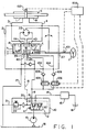
- FIG. 1 is a hydraulic circuit diagram of an embodiment of the invention when in the neutral condition.
- FIG. 2 is a longitudinally sectional view of a typical example of a steering unit of the type shown schematically in FIG. 1.
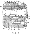
- FIG. 3 is a fragmentary, enlarged view of a portion of the steering unit shown in FIG. 2.
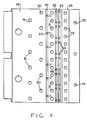
- FIG. 4 is a developed view of the surface of the sleeve of the steering unit shown in FIG. 2.
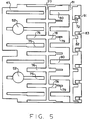
- FIG. 5 is a developed view of the surface of the spool of the steering unit shown in FIG. 2.
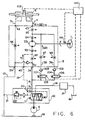
- FIG. 6 is a hydraulic circuit diagram of the embodiment during the normal steering operation.
- FIG. 7 is a hydraulic circuit diagram of the same embodiment when the stroke of the cylinder is short with respect to the rotation of the handle.
- FIG. 8 is a hydraulic circuit diagram of the same embodiment when the stroke of the cylinder is over with respect to the rotation of the handle.
- FIGs. 9-(A), -(B) and -(C) are graphs showing the relations with respect to the target set value between the rotation of the handle and the stroke of the cylinder in FIGs. 6, 7 and 8, respectively.
- FIG. 1 illustrates a system including a steering unit 2 having a directional control valve 7 operated by a handle 1.
- a steering cylinder 5 is connected the steering unit 2 through first hydraulic pressure lines 3 and 4 comprising a pair of left and right lines, and the cylinder 5 steers a steered wheel (or typically, a pair of steered wheels, not shown herein).
- a pump 6 comprises part of a hydraulic power source for supplying hydraulic pressure to the steering unit 2 through a second hydraulic pressure line 8.
- Reference numeral 10 designates a flow rate compensating valve, a valve body 12 being biased in one direction by a spring 11 which is provided in a casing. Oil flows into the valve 10 from a pump 6 and is fed, on the one hand, into a steering unit 2 from an inlet port 34 thereof to be discussed below through the second hydraulic pressure line 8, and on the other hand, into an actuator 15 through a separate pipe line 14.
- a pilot port 40 at the steering unit 2 communicates with both sides of the valve body 12 of the pressure and flow rate compensating valve 10 through a pilot hydraulic pressure line 18, and orifices 19 and 20 are provided in the hydraulic pressure line 18, at the spring 11 side of the valve 10.
- Hydraulic pressure line 18 is provided with a pipe line 21 communicating with the pipe line 17, and a relief valve 22 is provided in the pipe line 21.
- Reference numeral 31 designates a housing. At the right end thereof are disposed, in order, a spacer plate 32, an amplified portion 33 (also referred to as a fluid meter), and an end cap 28, which are coupled with the housing 31 through bolts 29.
- a spacer plate 32 At the right end thereof are disposed, in order, a spacer plate 32, an amplified portion 33 (also referred to as a fluid meter), and an end cap 28, which are coupled with the housing 31 through bolts 29.
- an inlet port 34 In the housing 31 are formed an inlet port 34, an outlet port 35, first and second auxiliary inlet ports 38, and 39, a pilot port 40, a right-hand port 43, and a left-hand port 44.
- a central bore 36 At a central bore 36 are formed annular grooves 41, 42, 45 and 50 communicating with the ports 34, 35, 43 and 44 respectively.
- a directional control valve 7 provided with a rotatable spool 47 and a relatively rotatable, follow-up sleeve 48 in association therewith.
- An input shaft 37 of the handle 1 is connected to one end of the spool 47.
- a centering spring 49 is fitted at both ends into through-bores provided in the spool 47 and sleeve 48, and 51 designates a stopper pin which circumferentially movably extends at both ends thereof through bores 52 at the spool 47 and thereafter is supported by through-bores at the sleeve 48.
- 53 designates a driving shaft which transmits rotary motion from the amplified portion (meter) 33 to the sleeve 48.
- the driving shaft 53 is provided at one axial end with a bifurcated portion through which the stopper pin 51 extends and at the other axial end with a splined head 54.
- the amplified portion 33 has an internally toothed member 55 and an externally toothed member 56 engageable with the internal teeth of internally toothed member 55, having teeth less by one in number than the internally toothed member 55, and provided eccentrically therein, so as to perform both orbital movement and rotation.
- Splines 57 are provided at the center bore of the externally toothed member 56 and engage with the splined head of driving shaft 53.
- the sleeve 48 is provided with an annular groove 65 communicating with the annular groove 41 at the housing 31, through-bores 59, 60 and 61 communicating with the annular grooves 42, 45 and 50 respectively, and annular grooves 62, 63 and 64 communicating with the ports 38, 39 and 40 respectively. Furthermore, the sleeve 48, as shown in FIG. 4, is provided with the through-bores 68, 69 and 58 communicating with the annular grooves 62, 63 and 65 respectively.
- a slanted through-bore 67 communicates with the annular groove 64, a plurality of radial through-bores 71 is disposed axially between the annular grooves 62 and 64, and a plurality through-bores 72 is disposed rightwardly from the annular groove 65.
- the spool 47 as shown in FIG. 5, is provided with axial grooves 75 communicating in part with the through bores 52.
- Axial grooves 76 are disposed alternately with the grooves 75, and an annular groove 77 circumferentially communicates with the grooves 76.
- An axial groove 78 extends from the annular groove 77 in a direction opposite to that of the grooves 76, a smaller width groove 79 extending from the utmost end of each groove 78 in the same direction as the groove 78 (i.e., to the right in FIG. 5).
- Axial grooves 80 are disposed alternately with the axial grooves 78, an annular groove 81 circumferentially communicating with the grooves 80, and axial grooves 82 extending from the annular groove 81 in a direction opposite that of the axial grooves 80.
- An axial groove 83 extends from an intermediate portion of each axial groove 82, to the right in FIG. 5, to the edge of the spool 47.
- the housing 31 is provided with a radial bore 86 communicating with the through-bore 71 at the sleeve 48, and a bore 87 axially extending from the end of bore 86 to the amplified portion 33, the bore 87 communicating with a through-bore 88 provided in a spacer plate 32, the through-bore 88 communicating with a pressure chamber 89 at the amplified portion 33.
- a first orifice 91 (shown only in FIG. 1), is formed between the through-bores 72 at the sleeve 48 and the axial grooves 82 and 83 at the spool 47.
- a second orifice 92 (also referred to as the A1 orifice) is formed between the through-bores 58 at the sleeve 48 and the axial grooves 80 at the spool 47.
- a third orifice 93 (also referred to as the A2 orifice) is formed between the through-bores 71 at the sleeve 48 and the axial groove 80 at the spool 47.
- a fourth orifice 94 also referred to as the A3 orifice is formed between the through-bores 71 at the sleeve 48 and the axial grooves 78 at the spool 47.
- a fifth orifice 95 (also referred to as the A4 orifice) is formed between the through-bores 60 at the sleeve 48 and the axial grooves 76 at the spool 47.
- a sixth orifice 96 (also referred to as the A5 orifice) is formed between the through-bores 61 at the sleeve 48 and the axial grooves 75 at the spool 47.
- a seventh orifice 97 is formed between the through-bore 68 at the sleeve 48 and the axial groove 79 at the spool 47
- an eighth orifice 98 is formed between the through-bore 69 at the sleeve 48 and the axial groove 79 at the spool 47.
- the apparatus of the present invention is provided with a controller 100, as shown in FIG. 1, which includes a second detecting member 102, for detecting the linear position of the cylinder 5.
- First and second auxiliary open-close valves 105 and 106 (which may preferably be solenoid valves) are provided in third and fourth hydraulic pressure lines 103 and 104, for communicating the second hydraulic pressure line 8 with the first and second auxiliary inlet ports 38 and 39, respectively.
- a first detecting member 101 comprises a rotational angle sensor for the handle 1 and is disposed adjacent the input shaft 37.
- Check valves 108 and 109 are provided in the third and fourth hydraulic pressure lines 103 and 104, on the downstream sides of the first and second auxiliary open-close valves 105 and 106, respectively.
- the flow rate of oil is determined by the orifice 19, and the pressure of the spring 11 at the pressure and flow rate compensating valve 10.
- the flow rate is reduced by the relation between the orifice 19 and the pressure of the spring 11, resulting in that most of the oil discharged from the pump 6 flows to the actuator 15 through the pipe line 14.
- the directional control valve 7 is in the neutral position and is blocked in the same way as the conventional one, thereby preventing the oil from flowing through the steering unit 2.
- the centering spring 49 in the steering unit 2 deflects to cause angular displacement between the sleeve 48 and the spool 47, so that each orifice 92 through 98 begins to open.
- the first orifice 91 which comprises the axial grooves 82 and 83 at the spool 47 and the through-bore 72, and is open when the handle is positioned in the neutral position, begins to close.
- oil which flows into the steering unit 2 from the inlet port 34 at the housing 31, through the pressure and flow rate compensating valve 10 and second hydraulic pressure line 8 passes through the annular groove 41 at the housing 31, annular groove 65 at the sleeve 48, second orifice 92 composed of the through-bore 58 at the sleeve 48 and axial groove 80 at the spool 47, and third orifice 93 composed of the through-bore 71 at the sleeve 48 and axial groove 78 at the spool 47.
- This fluid flows to the bores 86 and 87 at the housing 31, and passes through the through-bore 88 at the spacer plate 32 to rotate the externally toothed member 56 at the amplified portion 33.
- the portion 33 thereby measures an amount of discharged oil.
- the oil again passes through the bores 86 at the housing 31, through the fourth orifice 94 composed of the through-bore 71 at the sleeve 48 and groove 78 at the spool 47, the axial groove 78 at the spool 47, the annular groove 77, and the axial groove 76, and flows to the cylinder 5 from the right-hand port 43 through the fifth orifice 95, composed of the through bore 60 at the sleeve 48 and axial groove 76 at the spool 47 and through the annular groove 45 at the housing 31.
- the flow rate is Q1+q, the same as in the conventional apparatus.
- the first auxiliary open-close valve 105 is open, so that oil flowing therein flows to the first auxiliary inlet port 38 at the steering unit 2 through the third hydraulic pressure line 103.
- the oil flows to the annular groove 62 at the sleeve 48, passes through the seventh orifice 97, composed of the through-bore 68 at the sleeve 48 and axial groove 79 at the spool 47, and flows with the flow rate Q21 to the fifth orifice 95, then to the cylinder 5, in the same way as the aforesaid oil, thereby obtaining the total flow rate Q1+Q21+q into the cylinder 5.
- a corresponding amount of rotation of handle 1 to a stroke of cylinder 5 is determined as a target setting value as shown in FIG. 9-(A) and input to the controller 100.
- Return oil from the cylinder 5 flows into the steering unit 2 through the left-hand port 44 and to the sixth orifice 96, composed of the through-bore 61 at the sleeve 48 and axial groove at the spool 47 from the annular groove 50 at the housing 31, so as to pass through the inside of the spool 47 and return from the external port 35 to the tank 16.
- flow rates Q21 and Q22 of correction flow are not affected by load pressure, or the like, of the cylinder 5, but instead, are decided by the area of each orifice 97 and 98, respectively.
- the area of the orifices 97 and 98 correspond to the angular displacement between the spool 47 and the sleeve 48 following the rotation of handle 1. Accordingly, the area of each orifice is changed to enable the flow rate of correction oil to be changed, thereby enabling a proper amount of oil to be supplied.
- Pressure of cylinder 5 is not different from the correction pressure of the third and fourth hydraulic pressure lines 103 and 104 during the correction, and therefore, an operator is not subjected to an uncomfortable feeling, such as a shock on the vehicle body.
- auxiliary open-close valves 105 and 106, and the check valves 108 and 109 which are illustrated as being separate from the steering unit 2, may be integral therewith, i.e., may be built into the housing 31, but are separate from the directional control valve 7.
- a circuit which is capable of putting both the auxiliary open-close valves 105 and 106 simultaneously open or closed.
- both the auxiliary open-close valves 105 and 106 are closed, the stroke of cylinder 5 is small with respect to the rotation of handle 1, thereby improving the straight forward running efficiency. Accordingly, it is possible to perform relatively fine steering in a restricted place.
- both the auxiliary valves 105 and 106 are open, the stroke of cylinder 5 becomes larger with respect to the rotation of handle 1, thereby enabling the work efficiency to be improved, by increasing the "gain" of the system, i.e., the amount of movement of the cylinder 5 per unit of rotation of the handle 1.
- the conventional steering apparatus is provided at the third and fourth hydraulic pressure lines with the check valves 108 and 109, respectively, so that when the cylinder stroke is short with respect to the rotation of handle, the controller opens or closes the first and second auxiliary open-close valves 105 and 106 by the appropriate signal from the first and second detecting members 101 and 102, respectively, thereby correcting the over and short conditions.
- the apparatus is advantageous in that the neutral position of the cylinder 5 can be identified with the neutral position of the handle 1, and fluid may be continuously supplied during the normal steering so as to prevent idling of the handle. Even in emergency steering situations, if oil discharged from the hydraulic pressure source stops during the steering, the oil discharge corresponding to the torque of the handle 1 continues, thereby enabling the steering to be continued.
- valves 105 and 106 have been illustrated and described as separate valve members, in order to explain the concept, it should be apparent to those skilled in the art that a single proportional solenoid valve could be used instead.
Claims (15)
- Vollhydraulische Servolenkeinrichtung mit einer Lenkeinheit (2), die ein Richtungssteuerventil (7) aufweist, das mittels eines handbetätigten Eingabeorgans (1) betätigt wird; einem Lenkzylinder (5), der mit der Lenkeinheit über erste Hydraulikdruckleitungen, zu denen eine Linksleitung (3) und eine Rechtsleitung (4) gehören, verbunden ist und der ein gelenktes Rad lenkt; einer Hydraulikkraftquelle (6, 10) zum Beaufschlagen des Lenkzylinders mit Hydraulikdruck über die Lenkeinheit und die ersten Hydraulikdruckleitungen; einer zweiten Hydraulikdruckleitung (8) zum Verbinden der Hydraulikkraftquelle (6, 10) und der Lenkeinheit (2); einem ersten (101) und einem zweiten (102) Detektorglied zur Ausgabe von Signalen entsprechend einer Verlagerung des handbetätigten Eingabeorgans (1) bzw. des Lenkzylinders (5) aus der betreffenden Neutralstellung; und einem Steuergerät (100), in das Signale von den Detektorgliedern (101, 102) eingebbar sind;
gekennzeichnet durch:(a) eine dritte Hydraulikdruckleitung (103) und eine vierte Hydraulikdruckleitung (104), welche die zweite Hydraulikdruckleitung (8) mit der Lenkeinheit (2) verbinden und in welchen ein erstes (105) bzw. ein zweites (106) Absperr-Hilfsventil liegen; wobei das Öffnen und Schließen der Absperr-Hilfsventile (105, 106) mittels des Steuergerätes (100) bewirkt wird; und(b) Rückschlagventile (108, 109), die in der dritten (103) bzw. der vierten (104) Hydraulikleitung liegen. - Servolenkeinrichtung nach Anspruch 1, dadurch gekennzeichnet, daß die Lenkeinheit (2) eine Verstärkeranordnung (33) aufweist, welche das Richtungssteuerventil (7) zu einer Nachlaufbewegung veranlaßt, die proportional zu dem Volumen des Fluidstromes durch die Verstärkeranordnung ist.
- Servolenkeinrichtung nach Anspruch 1, dadurch gekennzeichnet, daß das Richtungssteuerventil (7) eine mittels des handbetätigten Eingabeorgans (1) betätigbare drehbare Ventilspule (47) und eine damit zusammenwirkende Ventilhülse (48) aufweist, die mit Bezug auf die Ventilspule drehbar ist.
- Servolenkeinrichtung nach Anspruch 1, dadurch gekennzeichnet, daß die Lenkeinheit (2) mit einem Gehäuse (31) versehen ist, das einen mit der zweiten Hydraulikdruckleitung (8) verbundenen Einlaßanschluß (34) und einen Rechtsanschluß (43) sowie einen Linksanschluß (44) aufweist, die mit den ersten Hydraulikdruckleitungen (3, 4) verbunden sind.
- Servolenkeinrichtung nach Anspruch 4, dadurch gekennzeichnet, daß die dritte (103) und die vierte (104) Hydraulikdruckleitung außerhalb des Gehäuses (31) der Lenkeinheit (2) angeordnet sind und das Gehäuse mit einem ersten (38) und einem zweiten (39) Hilfseinlaßanschluß versehen ist, die mit der dritten (103) bzw. der vierten (104) Hydraulikdruckleitung verbunden sind.
- Servolenkeinrichtung nach Anspruch 5, dadurch gekennzeichnet, daß die Lenkeinheit (2) eine Verstärkeranordnung (33) aufweist, die strömungsmäßig in Reihe in einem Hauptfluidweg liegt, welcher den Einlaßanschluß (34) und einen der Rechts- und Linksanschlüsse (43 bzw. 44) verbindet, wobei das Gehäuse (31) und das Richtungssteuerventil (7) gemeinsam einen ersten und einen zweiten Verstärkungsstromweg bilden, zu denen eine erste und eine zweite verstellbare Verstärkungsdrosselöffnung (97 bzw. 98 gehören, die eine Verbindung zwischen dem ersten (38) bzw. dem zweiten (39) Hilfseinlaßanschluß und dem Hauptfluidweg stromabwärts von der Verstärkeranordnung (33) herstellen.
- Servolenkeinrichtung nach Anspruch 1, dadurch gekennzeichnet, daß das erste und das zweite Absperr-Hilfsventil (105 bzw. 106) Magnetventile aufweisen, die in Abhängigkeit von von dem Steuergerät (100) kommenden elektrischen Eingangssignalen unabhängig betätigbar sind, um sich zwischen einer Schließstellung und einer Offenstellung zu bewegen.
- Servolenkeinrichtung nach Anspruch 7, dadurch gekennzeichnet, daß das Steuergerät (100) betätigbar ist, um die von dem ersten und dem zweiten Detektorglied (100 bzw. 102) ausgegebenen Signale zu vergleichen und grobe und feine Fehlerkorrektursignale zu erzeugen, und daß mittels elektrischer Eingangssignale, die von dem Steuergerät (100) übermittelt werden, eines der Absperr-Hilfsventile (105 oder 106) in die Offenstellung verstellbar ist, wenn das Fehlerkorrektursignal fein ist, und beide Absperr-Hilfsventile in die Offenstellung verstellbar sind, wenn das Fehlerkorrektursignal grob ist.
- Vollhydraulische Servolenkeinrichtung mit einer Lenkeinheit (2), die ein Richtungssteuerventil (7) aufweist, das mittels eines handbetätigten Eingabeorgans (1) betätigt wird; einem Lenkzylinder (5), der mit der Lenkeinheit über eine Links-Hydraulikdruckleitung (3) und eine Rechts-Hydraulikdruckleitung (4) verbunden ist, um ein gelenktes Rad zu lenken; einer Hydraulikkraftquelle (6, 10) zum Beaufschlagen des Lenkzylinders mit Hydraulikdruck über die Lenkeinheit und die Links- und Rechts-Hydraulikdruckleitungen; einer Hydraulikdruck-Einlaßleitung (8) zum Verbinden der Hydraulikkraftquelle (6, 10) und der Lenkeinheit (2); einer Detektoranordnung (101, 102) zum Erfassen eines vorbestimmten Zustandes der Servolenkeinrichtung und zur Ausgabe eines Signals entsprechend dem erfaßten Zustand; und einem Steuergerät (100), in welches das von der Detektoranordnung (101, 102) ausgegebene Signal eingebbar ist; wobei die Lenkeinheit ein Gehäuse (31) aufweist, das zusammen mit dem Richtungssteuerventil (7) einen Hauptfluidweg bildet, welcher einen Einlaßanschluß (34) mit der Links-Hydraulikdruckleitung (3) oder der Rechts-Hydraulikdruckleitung (4) verbindet; wobei die Lenkeinheit ferner mit einem Fluiddosiergerät (33) versehen ist, welches das Richtungssteuerventil (7) zu einer Nachlaufbewegung veranlaßt, die dem Volumen des Fluidstromes durch das Fluiddosiergerät proportional ist; und wobei das Fluiddosiergerät in dem Hauptfluidweg strömungsmäßig in Reihe liegt; gekennzeichnet durch:(a) eine Hydraulikleitungsanordnung (103) zum Verbinden der Hydraulikdruck-Einlaßleitung (8) mit einem Verstärkungsanschluß (38);(b) einer in der Hydraulikleitungsanordnung (103) liegenden Hilfsventilanordnung (105), mittels deren der durch die Hilfsventilanordnung hindurchtretende Strom in Abhängigkeit von einem von dem Steuergerät (100) erzeugten Eingangssignal steuerbar ist; und(c) wobei das Gehäuse (31) und das Richtungssteuerventil (7) gemeinsam einen Verstärkungsstromweg bilden, zu dem eine verstellbare Verstärkungsdrosselöffnung (97) gehört, die für eine Verbindung zwischen dem Verstärkungsanschluß (38) und dem Hauptfluidweg stromabwärts von dem Fluiddosiergerät (33) sorgt.
- Servolenkeinrichtung nach Anspruch 9, dadurch gekennzeichnet, daß das Richtungssteuerventil (7) eine mittels des handbetätigten Eingabeorgans (1) betätigbare drehbare Ventilspule (47) und eine damit zusammenwirkende Ventilhülse (48) aufweist, die mit Bezug auf die Ventilspule drehbar ist.
- Servolenkeinrichtung nach Anspruch 10, dadurch gekennzeichnet, daß die verstellbare Verstärkungsdrosselöffnung (97) an einer Grenzfläche zwischen der Ventilspule (47) und der Ventilhülse (48) gebildet ist und eine Durchflußfläche hat, die in Abhängigkeit von der relativen Drehbewegung zwischen der Ventilspule und der Ventilhülse verstellbar ist.
- Servolenkeinrichtung nach Anspruch 9, dadurch gekennzeichnet, daß die Hydraulikleitungsanordnung (103) außerhalb des Gehäuses (31) der Lenkeinheit (2) angeordnet ist.
- Servolenkeinrichtung nach Anspruch 12, dadurch gekennzeichnet, daß die Hilfsventilanordnung (105) außerhalb des Gehäuses (31) angeordnet ist und der Strom durch die Hilfsventilanordnung in Abhängigkeit von einem elektrischen Eingangssignal steuerbar ist.
- Servolenkeinrichtung nach Anspruch 9, dadurch gekennzeichnet, daß die Detektoranordnung (101, 102) Mittel zum Erfassen der Stellung des handbetätigten Eingabeorgans (1) und Mittel (102) zum Erfassen der Stellung des Lenkzylinders (5) aufweist.
- Servolenkeinrichtung nach Anspruch 9, gekennzeichnet durch eine weitere Hydraulikleitungsanordnung (104) zum Verbinden der Hydraulikdruck-Einlaßleitung (8) mit einem weiteren Verstärkungsanschluß (39), eine in der weiteren Leitungsanordnung (104) liegenden weitere Hilfsventilanordnung (106), mittels deren der Strom durch die weitere Hilfsventilanordnung in Abhängigkeit von einem weiteren Eingangssignal steuerbar ist; wobei das Steuergerät (100) betätigbar ist, um das weitere Eingangssignal zu erzeugen; und wobei das Gehäuse (31) und das Richtungssteuerventil (7) gemeinsam einen weiteren Verstärkungsstromweg bilden, zu dem eine weitere verstellbare Verstärkungsdrosselöffnung (98) gehört, die eine Verbindung zwischen dem weiteren Verstärkungsanschluß (39) und dem Hauptfluidweg stromabwärts von dem Fluiddosiergerät (33) herstellt.
Applications Claiming Priority (2)
| Application Number | Priority Date | Filing Date | Title |
|---|---|---|---|
| JP1177957A JP2669474B2 (ja) | 1989-07-12 | 1989-07-12 | 全油圧式パワーステアリング装置 |
| JP177957/89 | 1989-07-12 |
Publications (2)
| Publication Number | Publication Date |
|---|---|
| EP0407768A1 EP0407768A1 (de) | 1991-01-16 |
| EP0407768B1 true EP0407768B1 (de) | 1993-12-01 |
Family
ID=16040038
Family Applications (1)
| Application Number | Title | Priority Date | Filing Date |
|---|---|---|---|
| EP90111582A Expired - Lifetime EP0407768B1 (de) | 1989-07-12 | 1990-06-19 | Vollhydraulische Servolenkeinrichtung |
Country Status (4)
| Country | Link |
|---|---|
| US (1) | US5020618A (de) |
| EP (1) | EP0407768B1 (de) |
| JP (1) | JP2669474B2 (de) |
| DE (1) | DE69004877T2 (de) |
Cited By (1)
| Publication number | Priority date | Publication date | Assignee | Title |
|---|---|---|---|---|
| US6912455B2 (en) | 2002-06-11 | 2005-06-28 | Sauer-Danfoss (Nordborg) A/S | Vehicle steering system and method of steering |
Families Citing this family (35)
| Publication number | Priority date | Publication date | Assignee | Title |
|---|---|---|---|---|
| WO1990012725A1 (en) * | 1989-04-18 | 1990-11-01 | Kabushiki Kaisha Komatsu Seisakusho | Steering wheel position compensator of fully hydraulic steering system |
| JPH0345471A (ja) * | 1989-07-14 | 1991-02-27 | Komatsu Ltd | 全油圧式ステアリングシステムのハンドル位置補正装置 |
| US5115640A (en) * | 1990-04-23 | 1992-05-26 | Eaton Corporation | Fluid controller and logic control system for use therewith |
| US5303636A (en) * | 1990-04-23 | 1994-04-19 | Eaton Corporation | Fluid controller and logic control system for use therewith |
| DE4031951C2 (de) * | 1990-10-09 | 1994-06-09 | Danfoss As | Hydraulisches Lenksystem für Fahrzeuge |
| DE4042151C2 (de) * | 1990-12-28 | 1996-12-12 | Danfoss As | Steuereinrichtung für ein vollhydraulisches Lenksystem |
| JP2791244B2 (ja) * | 1992-03-19 | 1998-08-27 | 住友イートン機器株式会社 | 入力検出装置付全油圧パワーステアリング装置 |
| US5549173A (en) * | 1993-10-13 | 1996-08-27 | Sumitomo Precision Products Co., Ltd. | Control device for hydraulic actuator used in steering |
| US5596498A (en) * | 1994-01-14 | 1997-01-21 | Danfoss A/S | Hydraulic steering arrangement for vehicles |
| US5520262A (en) * | 1995-04-28 | 1996-05-28 | Caterpillar Inc. | Electrohydraulic steering system |
| JP3641514B2 (ja) * | 1995-08-24 | 2005-04-20 | ティーアールダブリュ オートモーティブ ジャパン株式会社 | 電動式パワーステアリング装置 |
| ES2121457T3 (es) * | 1996-11-02 | 1998-11-16 | Hydraulik Nord Gmbh | Mecanismo hidraulico de direccion con variacion de la transmision e intensificacion de corriente. |
| US5960694A (en) * | 1998-02-23 | 1999-10-05 | Eaton Corporation | Hydrostatic power steering system having reduced wheel slip |
| DE19841101C2 (de) * | 1998-09-09 | 2000-06-21 | Daimler Chrysler Ag | Lenksystem für nicht spurgebundene Kraftfahrzeuge |
| US6076349A (en) * | 1999-04-29 | 2000-06-20 | Eaton Corporation | Hydrostatic automotive or high speed steering system |
| DE19945122B4 (de) * | 1999-09-21 | 2004-08-12 | Sauer-Danfoss Holding Aps | Hydraulische Steuereinrichtung |
| US6218336B1 (en) * | 1999-10-26 | 2001-04-17 | Applied Carbochemicals | Enhanced herbicides |
| DE19962124A1 (de) * | 1999-12-21 | 2001-07-12 | Sauer Danfoss Nordborg As Nord | Hydraulisches Zweikreis-Lenksystem |
| US6560961B2 (en) * | 2001-09-18 | 2003-05-13 | Eaton Corporation | Steering system with ability to stop steering wheel rotation |
| DE50303334D1 (de) * | 2002-04-18 | 2006-06-22 | Still Gmbh | Hydraulische Lenkeinrichtung |
| JP4156271B2 (ja) * | 2002-05-16 | 2008-09-24 | 株式会社アミテック | パワーステアリング装置用制御ユニット |
| DE10259038A1 (de) * | 2002-12-17 | 2004-07-08 | Still Gmbh | Hydraulischer Antrieb |
| WO2004082548A2 (en) * | 2003-03-20 | 2004-09-30 | R82 A/S | Active wheelchair |
| DE102006010696B4 (de) * | 2006-03-08 | 2009-01-22 | Sauer-Danfoss Aps | Hydraulische Lenkung |
| DE102006010695B4 (de) * | 2006-03-08 | 2009-05-14 | Sauer-Danfoss Aps | Hydraulische Lenkung |
| DE102006010697B4 (de) | 2006-03-08 | 2009-01-22 | Sauer-Danfoss Aps | Hydraulische Lenkung |
| US7913800B2 (en) * | 2006-10-30 | 2011-03-29 | Deere & Company | Steering system with variable flow rate amplification ratio and associated method |
| DE102006051541B4 (de) * | 2006-11-02 | 2009-06-04 | Sauer-Danfoss Aps | Hydraulische Lenkeinrichtung |
| US7984785B2 (en) | 2008-02-28 | 2011-07-26 | Eaton Corporation | Control valve assembly for electro-hydraulic steering system |
| US7931112B2 (en) * | 2008-05-02 | 2011-04-26 | Eaton Corporation | Isolation valve for a load-reaction steering system |
| BRPI1003170B1 (pt) * | 2010-08-31 | 2018-05-29 | Agco Do Brasil Máquinas E Equipamentos Agrícolas Ltda. | Sistema hidráulico para tratores agrícolas |
| US11408445B2 (en) | 2018-07-12 | 2022-08-09 | Danfoss Power Solutions Ii Technology A/S | Dual power electro-hydraulic motion control system |
| US11104234B2 (en) | 2018-07-12 | 2021-08-31 | Eaton Intelligent Power Limited | Power architecture for a vehicle such as an off-highway vehicle |
| DE102018125049B4 (de) * | 2018-10-10 | 2020-08-20 | Danfoss Power Solutions Aps | Hydraulische Lenkanordnung |
| CN113830169B (zh) * | 2021-11-26 | 2022-03-04 | 徐工集团工程机械股份有限公司科技分公司 | 一种安全液压转向系统及其控制方法 |
Family Cites Families (4)
| Publication number | Priority date | Publication date | Assignee | Title |
|---|---|---|---|---|
| DE2123933C3 (de) * | 1971-05-14 | 1981-07-16 | Zahnradfabrik Friedrichshafen Ag, 7990 Friedrichshafen | Hydrostatische Hilfskraft-Lenkeinrichtung |
| US4703819A (en) * | 1985-02-27 | 1987-11-03 | Nissan Motor Co., Ltd. | Full hydraulic power steering system |
| JPS63195064A (ja) * | 1987-02-10 | 1988-08-12 | Toyota Autom Loom Works Ltd | 全油圧式パワ−ステアリング装置 |
| US4759182A (en) * | 1987-07-24 | 1988-07-26 | Eaton Corporation | Steering control unit with flow amplification |
-
1989
- 1989-07-12 JP JP1177957A patent/JP2669474B2/ja not_active Expired - Fee Related
-
1990
- 1990-06-13 US US07/537,403 patent/US5020618A/en not_active Expired - Lifetime
- 1990-06-19 DE DE90111582T patent/DE69004877T2/de not_active Expired - Lifetime
- 1990-06-19 EP EP90111582A patent/EP0407768B1/de not_active Expired - Lifetime
Cited By (1)
| Publication number | Priority date | Publication date | Assignee | Title |
|---|---|---|---|---|
| US6912455B2 (en) | 2002-06-11 | 2005-06-28 | Sauer-Danfoss (Nordborg) A/S | Vehicle steering system and method of steering |
Also Published As
| Publication number | Publication date |
|---|---|
| JPH0345470A (ja) | 1991-02-27 |
| DE69004877D1 (de) | 1994-01-13 |
| DE69004877T2 (de) | 1994-04-21 |
| EP0407768A1 (de) | 1991-01-16 |
| US5020618A (en) | 1991-06-04 |
| JP2669474B2 (ja) | 1997-10-27 |
Similar Documents
| Publication | Publication Date | Title |
|---|---|---|
| EP0407768B1 (de) | Vollhydraulische Servolenkeinrichtung | |
| EP0300269B1 (de) | Lenkungssteuereinheit mit Strömungsverstärkung | |
| EP0038542B1 (de) | Druckmittelbetätigtes Steuergerät | |
| EP0388711B1 (de) | Steuereinheit für eine Lenkung mit Durchflussverstärkung und offener Mitte | |
| US3996838A (en) | Diverter valve for power steering with power beyond | |
| US6539710B2 (en) | Hydrostatic steering system having improved steering sensing | |
| US6560961B2 (en) | Steering system with ability to stop steering wheel rotation | |
| US4558720A (en) | Closed-center controller for use with unequal area cylinder | |
| EP0362534B1 (de) | Lenkungssteuereinheit mit Strömungsverstärkung und Handsteuermöglichkeit | |
| EP1048549B1 (de) | Hydrostatische Kraftfahrzeugservolenkung für erhöhte Geschwindigkeit | |
| US4828067A (en) | Electronic power assist control steering system | |
| EP0480431B1 (de) | Steuergerät mit verringertem Schlupf des Endausschlags | |
| USRE34746E (en) | Open-center steering control unit with flow amplification | |
| EP0545113B1 (de) | Hydraulisches Ventil mit integriertem Hilfsventil | |
| US5609221A (en) | Steering control system | |
| EP0561401B1 (de) | Hydraulische Servolenkungseinrichtung mit Eingabeerkennungsmöglichkeit | |
| EP0264613A2 (de) | Flüssigkeitssteuerung und gedämpfter Flüssigkeitsweg | |
| US3957129A (en) | Steering system | |
| US5244052A (en) | Steering control unit for multiple steerable axles | |
| JP2669473B2 (ja) | 全油圧式パワーステアリング装置 | |
| JP2659097B2 (ja) | 全油圧式パワーステアリング装置 | |
| US7490626B2 (en) | Steer valve with hydraulic vehicle position feedback |
Legal Events
| Date | Code | Title | Description |
|---|---|---|---|
| PUAI | Public reference made under article 153(3) epc to a published international application that has entered the european phase |
Free format text: ORIGINAL CODE: 0009012 |
|
| AK | Designated contracting states |
Kind code of ref document: A1 Designated state(s): DE FR GB IT |
|
| 17P | Request for examination filed |
Effective date: 19910204 |
|
| 17Q | First examination report despatched |
Effective date: 19921002 |
|
| GRAA | (expected) grant |
Free format text: ORIGINAL CODE: 0009210 |
|
| AK | Designated contracting states |
Kind code of ref document: B1 Designated state(s): DE FR GB IT |
|
| REF | Corresponds to: |
Ref document number: 69004877 Country of ref document: DE Date of ref document: 19940113 |
|
| ITF | It: translation for a ep patent filed |
Owner name: ING. C. GREGORJ S.P.A. |
|
| ET | Fr: translation filed | ||
| PLBE | No opposition filed within time limit |
Free format text: ORIGINAL CODE: 0009261 |
|
| STAA | Information on the status of an ep patent application or granted ep patent |
Free format text: STATUS: NO OPPOSITION FILED WITHIN TIME LIMIT |
|
| 26N | No opposition filed | ||
| REG | Reference to a national code |
Ref country code: GB Ref legal event code: IF02 |
|
| PGFP | Annual fee paid to national office [announced via postgrant information from national office to epo] |
Ref country code: IT Payment date: 20090620 Year of fee payment: 20 Ref country code: FR Payment date: 20090605 Year of fee payment: 20 |
|
| PGFP | Annual fee paid to national office [announced via postgrant information from national office to epo] |
Ref country code: GB Payment date: 20090507 Year of fee payment: 20 Ref country code: DE Payment date: 20090630 Year of fee payment: 20 |
|
| REG | Reference to a national code |
Ref country code: GB Ref legal event code: PE20 Expiry date: 20100618 |
|
| PG25 | Lapsed in a contracting state [announced via postgrant information from national office to epo] |
Ref country code: GB Free format text: LAPSE BECAUSE OF EXPIRATION OF PROTECTION Effective date: 20100618 |
|
| PG25 | Lapsed in a contracting state [announced via postgrant information from national office to epo] |
Ref country code: DE Free format text: LAPSE BECAUSE OF EXPIRATION OF PROTECTION Effective date: 20100619 |