EP0407768B1 - Full hydraulic power steering apparatus - Google Patents
Full hydraulic power steering apparatus Download PDFInfo
- Publication number
- EP0407768B1 EP0407768B1 EP90111582A EP90111582A EP0407768B1 EP 0407768 B1 EP0407768 B1 EP 0407768B1 EP 90111582 A EP90111582 A EP 90111582A EP 90111582 A EP90111582 A EP 90111582A EP 0407768 B1 EP0407768 B1 EP 0407768B1
- Authority
- EP
- European Patent Office
- Prior art keywords
- hydraulic pressure
- steering unit
- steering apparatus
- power steering
- hydraulic
- Prior art date
- Legal status (The legal status is an assumption and is not a legal conclusion. Google has not performed a legal analysis and makes no representation as to the accuracy of the status listed.)
- Expired - Lifetime
Links
Images


Classifications
-
- B—PERFORMING OPERATIONS; TRANSPORTING
- B62—LAND VEHICLES FOR TRAVELLING OTHERWISE THAN ON RAILS
- B62D—MOTOR VEHICLES; TRAILERS
- B62D5/00—Power-assisted or power-driven steering
- B62D5/06—Power-assisted or power-driven steering fluid, i.e. using a pressurised fluid for most or all the force required for steering a vehicle
- B62D5/09—Power-assisted or power-driven steering fluid, i.e. using a pressurised fluid for most or all the force required for steering a vehicle characterised by means for actuating valves
- B62D5/093—Telemotor driven by steering wheel movement
- B62D5/097—Telemotor driven by steering wheel movement gerotor type
Definitions
- the present invention relates to a full hydraulic power steering apparatus for a vehicle, especially an off-highway vehicle such as a tractor or construction vehicle.
- the kind of conventional apparatus (known e.g. from DE-A-21 23 933) is constructed as follows.
- the conventional apparatus is provided with a steering unit having a directional control valve operated by a handle, such as the vehicle steering wheel.
- a steering cylinder is connected with the steering unit through first hydraulic pressure lines comprising a pair of left and right lines, and steers a steered wheel.
- a pump of a hydraulic power source supplies hydraulic pressure to the steering unit through a second hydraulic pressure line.
- Such power steering apparatus can amend the displacement state with ease without shifting the target position of the cylinder with respect to the handle position.
- manual steering operation is intended to be carried out during the non-operation of a pump, the problem is created in that there is a fear that discharged oil is not supplied to the steering cylinder, but reversely flows.
- An object of the invention is to provide a power steering apparatus which allows to preserve registry or correspondence between the steered wheel and the steering wheel positions irrespective of leakage of hydraulic fluid or the like, and maintains the advantage of the power steering apparatus, so that, even when manually steered, it can prevent the discharged oil from reversely flowing.
- a full hydraulic power steering appartus of the type including a steering unit having a directional control valve operated by an input handle; a steering cylinder which is connected with said steering unit through first hydraulic pressure lines comprising a left line and a right line, and steers a steered wheel; a hydraulic power source for supplying hydraulic pressure to said steering cylinder through said steering unit and said first hydraulic pressure lines; a second hydraulic pressure line for connecting said hydraulic power source and said steering unit; first and second detection members for outputting signals corresponding to displacement from the neutral positions of said input handle and said steering cylinder, respectively; and a controller for inputting therein the signals from said detection members (with all the afore-mentioned features being known from DE-A-21 23 933); is characterized by:
- a full hydraulic power steering apparatus of the type including a steering unit having a directional control valve operated by an input handle; a steering cylinder which is connected with said steering unit through left and right hydraulic pressure lines to steer a steered wheel; a hydraulic power source for supplying hydraulic pressure to said steering cylinder through said steering unit and said left and right hydraulic pressure lines; an inlet hydraulic pressure line for connecting said hydraulic power source and said steering unit; detection means operable to detect a predetermined condition of said power steering apparatus and output a signal corresponding to said detected condition; and a controller for inputting said signal outputted by said detection means; said steering unit comprising a housing cooperating with said directional control valve to define a main fluid path connecting an inlet port to one of said left and right hydraulic pressure lines; said steering unit further comprising a fluid meter for imparting follow-up movement to said directional control valve proportional to the volume of fluid flow through said fluid meter, said fluid meter being disposed in series flow relationship in said main fluid path (with all the afore-
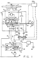
- FIG. 1 is a hydraulic circuit diagram of an embodiment of the invention when in the neutral condition.
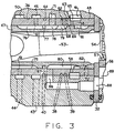
- FIG. 2 is a longitudinally sectional view of a typical example of a steering unit of the type shown schematically in FIG. 1.
- FIG. 3 is a fragmentary, enlarged view of a portion of the steering unit shown in FIG. 2.
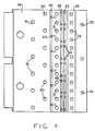
- FIG. 4 is a developed view of the surface of the sleeve of the steering unit shown in FIG. 2.
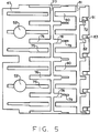
- FIG. 5 is a developed view of the surface of the spool of the steering unit shown in FIG. 2.
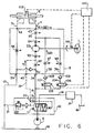
- FIG. 6 is a hydraulic circuit diagram of the embodiment during the normal steering operation.
- FIG. 7 is a hydraulic circuit diagram of the same embodiment when the stroke of the cylinder is short with respect to the rotation of the handle.
- FIG. 8 is a hydraulic circuit diagram of the same embodiment when the stroke of the cylinder is over with respect to the rotation of the handle.
- FIGs. 9-(A), -(B) and -(C) are graphs showing the relations with respect to the target set value between the rotation of the handle and the stroke of the cylinder in FIGs. 6, 7 and 8, respectively.
- FIG. 1 illustrates a system including a steering unit 2 having a directional control valve 7 operated by a handle 1.
- a steering cylinder 5 is connected the steering unit 2 through first hydraulic pressure lines 3 and 4 comprising a pair of left and right lines, and the cylinder 5 steers a steered wheel (or typically, a pair of steered wheels, not shown herein).
- a pump 6 comprises part of a hydraulic power source for supplying hydraulic pressure to the steering unit 2 through a second hydraulic pressure line 8.
- Reference numeral 10 designates a flow rate compensating valve, a valve body 12 being biased in one direction by a spring 11 which is provided in a casing. Oil flows into the valve 10 from a pump 6 and is fed, on the one hand, into a steering unit 2 from an inlet port 34 thereof to be discussed below through the second hydraulic pressure line 8, and on the other hand, into an actuator 15 through a separate pipe line 14.
- a pilot port 40 at the steering unit 2 communicates with both sides of the valve body 12 of the pressure and flow rate compensating valve 10 through a pilot hydraulic pressure line 18, and orifices 19 and 20 are provided in the hydraulic pressure line 18, at the spring 11 side of the valve 10.
- Hydraulic pressure line 18 is provided with a pipe line 21 communicating with the pipe line 17, and a relief valve 22 is provided in the pipe line 21.
- Reference numeral 31 designates a housing. At the right end thereof are disposed, in order, a spacer plate 32, an amplified portion 33 (also referred to as a fluid meter), and an end cap 28, which are coupled with the housing 31 through bolts 29.
- a spacer plate 32 At the right end thereof are disposed, in order, a spacer plate 32, an amplified portion 33 (also referred to as a fluid meter), and an end cap 28, which are coupled with the housing 31 through bolts 29.
- an inlet port 34 In the housing 31 are formed an inlet port 34, an outlet port 35, first and second auxiliary inlet ports 38, and 39, a pilot port 40, a right-hand port 43, and a left-hand port 44.
- a central bore 36 At a central bore 36 are formed annular grooves 41, 42, 45 and 50 communicating with the ports 34, 35, 43 and 44 respectively.
- a directional control valve 7 provided with a rotatable spool 47 and a relatively rotatable, follow-up sleeve 48 in association therewith.
- An input shaft 37 of the handle 1 is connected to one end of the spool 47.
- a centering spring 49 is fitted at both ends into through-bores provided in the spool 47 and sleeve 48, and 51 designates a stopper pin which circumferentially movably extends at both ends thereof through bores 52 at the spool 47 and thereafter is supported by through-bores at the sleeve 48.
- 53 designates a driving shaft which transmits rotary motion from the amplified portion (meter) 33 to the sleeve 48.
- the driving shaft 53 is provided at one axial end with a bifurcated portion through which the stopper pin 51 extends and at the other axial end with a splined head 54.
- the amplified portion 33 has an internally toothed member 55 and an externally toothed member 56 engageable with the internal teeth of internally toothed member 55, having teeth less by one in number than the internally toothed member 55, and provided eccentrically therein, so as to perform both orbital movement and rotation.
- Splines 57 are provided at the center bore of the externally toothed member 56 and engage with the splined head of driving shaft 53.
- the sleeve 48 is provided with an annular groove 65 communicating with the annular groove 41 at the housing 31, through-bores 59, 60 and 61 communicating with the annular grooves 42, 45 and 50 respectively, and annular grooves 62, 63 and 64 communicating with the ports 38, 39 and 40 respectively. Furthermore, the sleeve 48, as shown in FIG. 4, is provided with the through-bores 68, 69 and 58 communicating with the annular grooves 62, 63 and 65 respectively.
- a slanted through-bore 67 communicates with the annular groove 64, a plurality of radial through-bores 71 is disposed axially between the annular grooves 62 and 64, and a plurality through-bores 72 is disposed rightwardly from the annular groove 65.
- the spool 47 as shown in FIG. 5, is provided with axial grooves 75 communicating in part with the through bores 52.
- Axial grooves 76 are disposed alternately with the grooves 75, and an annular groove 77 circumferentially communicates with the grooves 76.
- An axial groove 78 extends from the annular groove 77 in a direction opposite to that of the grooves 76, a smaller width groove 79 extending from the utmost end of each groove 78 in the same direction as the groove 78 (i.e., to the right in FIG. 5).
- Axial grooves 80 are disposed alternately with the axial grooves 78, an annular groove 81 circumferentially communicating with the grooves 80, and axial grooves 82 extending from the annular groove 81 in a direction opposite that of the axial grooves 80.
- An axial groove 83 extends from an intermediate portion of each axial groove 82, to the right in FIG. 5, to the edge of the spool 47.
- the housing 31 is provided with a radial bore 86 communicating with the through-bore 71 at the sleeve 48, and a bore 87 axially extending from the end of bore 86 to the amplified portion 33, the bore 87 communicating with a through-bore 88 provided in a spacer plate 32, the through-bore 88 communicating with a pressure chamber 89 at the amplified portion 33.
- a first orifice 91 (shown only in FIG. 1), is formed between the through-bores 72 at the sleeve 48 and the axial grooves 82 and 83 at the spool 47.
- a second orifice 92 (also referred to as the A1 orifice) is formed between the through-bores 58 at the sleeve 48 and the axial grooves 80 at the spool 47.
- a third orifice 93 (also referred to as the A2 orifice) is formed between the through-bores 71 at the sleeve 48 and the axial groove 80 at the spool 47.
- a fourth orifice 94 also referred to as the A3 orifice is formed between the through-bores 71 at the sleeve 48 and the axial grooves 78 at the spool 47.
- a fifth orifice 95 (also referred to as the A4 orifice) is formed between the through-bores 60 at the sleeve 48 and the axial grooves 76 at the spool 47.
- a sixth orifice 96 (also referred to as the A5 orifice) is formed between the through-bores 61 at the sleeve 48 and the axial grooves 75 at the spool 47.
- a seventh orifice 97 is formed between the through-bore 68 at the sleeve 48 and the axial groove 79 at the spool 47
- an eighth orifice 98 is formed between the through-bore 69 at the sleeve 48 and the axial groove 79 at the spool 47.
- the apparatus of the present invention is provided with a controller 100, as shown in FIG. 1, which includes a second detecting member 102, for detecting the linear position of the cylinder 5.
- First and second auxiliary open-close valves 105 and 106 (which may preferably be solenoid valves) are provided in third and fourth hydraulic pressure lines 103 and 104, for communicating the second hydraulic pressure line 8 with the first and second auxiliary inlet ports 38 and 39, respectively.
- a first detecting member 101 comprises a rotational angle sensor for the handle 1 and is disposed adjacent the input shaft 37.
- Check valves 108 and 109 are provided in the third and fourth hydraulic pressure lines 103 and 104, on the downstream sides of the first and second auxiliary open-close valves 105 and 106, respectively.
- the flow rate of oil is determined by the orifice 19, and the pressure of the spring 11 at the pressure and flow rate compensating valve 10.
- the flow rate is reduced by the relation between the orifice 19 and the pressure of the spring 11, resulting in that most of the oil discharged from the pump 6 flows to the actuator 15 through the pipe line 14.
- the directional control valve 7 is in the neutral position and is blocked in the same way as the conventional one, thereby preventing the oil from flowing through the steering unit 2.
- the centering spring 49 in the steering unit 2 deflects to cause angular displacement between the sleeve 48 and the spool 47, so that each orifice 92 through 98 begins to open.
- the first orifice 91 which comprises the axial grooves 82 and 83 at the spool 47 and the through-bore 72, and is open when the handle is positioned in the neutral position, begins to close.
- oil which flows into the steering unit 2 from the inlet port 34 at the housing 31, through the pressure and flow rate compensating valve 10 and second hydraulic pressure line 8 passes through the annular groove 41 at the housing 31, annular groove 65 at the sleeve 48, second orifice 92 composed of the through-bore 58 at the sleeve 48 and axial groove 80 at the spool 47, and third orifice 93 composed of the through-bore 71 at the sleeve 48 and axial groove 78 at the spool 47.
- This fluid flows to the bores 86 and 87 at the housing 31, and passes through the through-bore 88 at the spacer plate 32 to rotate the externally toothed member 56 at the amplified portion 33.
- the portion 33 thereby measures an amount of discharged oil.
- the oil again passes through the bores 86 at the housing 31, through the fourth orifice 94 composed of the through-bore 71 at the sleeve 48 and groove 78 at the spool 47, the axial groove 78 at the spool 47, the annular groove 77, and the axial groove 76, and flows to the cylinder 5 from the right-hand port 43 through the fifth orifice 95, composed of the through bore 60 at the sleeve 48 and axial groove 76 at the spool 47 and through the annular groove 45 at the housing 31.
- the flow rate is Q1+q, the same as in the conventional apparatus.
- the first auxiliary open-close valve 105 is open, so that oil flowing therein flows to the first auxiliary inlet port 38 at the steering unit 2 through the third hydraulic pressure line 103.
- the oil flows to the annular groove 62 at the sleeve 48, passes through the seventh orifice 97, composed of the through-bore 68 at the sleeve 48 and axial groove 79 at the spool 47, and flows with the flow rate Q21 to the fifth orifice 95, then to the cylinder 5, in the same way as the aforesaid oil, thereby obtaining the total flow rate Q1+Q21+q into the cylinder 5.
- a corresponding amount of rotation of handle 1 to a stroke of cylinder 5 is determined as a target setting value as shown in FIG. 9-(A) and input to the controller 100.
- Return oil from the cylinder 5 flows into the steering unit 2 through the left-hand port 44 and to the sixth orifice 96, composed of the through-bore 61 at the sleeve 48 and axial groove at the spool 47 from the annular groove 50 at the housing 31, so as to pass through the inside of the spool 47 and return from the external port 35 to the tank 16.
- flow rates Q21 and Q22 of correction flow are not affected by load pressure, or the like, of the cylinder 5, but instead, are decided by the area of each orifice 97 and 98, respectively.
- the area of the orifices 97 and 98 correspond to the angular displacement between the spool 47 and the sleeve 48 following the rotation of handle 1. Accordingly, the area of each orifice is changed to enable the flow rate of correction oil to be changed, thereby enabling a proper amount of oil to be supplied.
- Pressure of cylinder 5 is not different from the correction pressure of the third and fourth hydraulic pressure lines 103 and 104 during the correction, and therefore, an operator is not subjected to an uncomfortable feeling, such as a shock on the vehicle body.
- auxiliary open-close valves 105 and 106, and the check valves 108 and 109 which are illustrated as being separate from the steering unit 2, may be integral therewith, i.e., may be built into the housing 31, but are separate from the directional control valve 7.
- a circuit which is capable of putting both the auxiliary open-close valves 105 and 106 simultaneously open or closed.
- both the auxiliary open-close valves 105 and 106 are closed, the stroke of cylinder 5 is small with respect to the rotation of handle 1, thereby improving the straight forward running efficiency. Accordingly, it is possible to perform relatively fine steering in a restricted place.
- both the auxiliary valves 105 and 106 are open, the stroke of cylinder 5 becomes larger with respect to the rotation of handle 1, thereby enabling the work efficiency to be improved, by increasing the "gain" of the system, i.e., the amount of movement of the cylinder 5 per unit of rotation of the handle 1.
- the conventional steering apparatus is provided at the third and fourth hydraulic pressure lines with the check valves 108 and 109, respectively, so that when the cylinder stroke is short with respect to the rotation of handle, the controller opens or closes the first and second auxiliary open-close valves 105 and 106 by the appropriate signal from the first and second detecting members 101 and 102, respectively, thereby correcting the over and short conditions.
- the apparatus is advantageous in that the neutral position of the cylinder 5 can be identified with the neutral position of the handle 1, and fluid may be continuously supplied during the normal steering so as to prevent idling of the handle. Even in emergency steering situations, if oil discharged from the hydraulic pressure source stops during the steering, the oil discharge corresponding to the torque of the handle 1 continues, thereby enabling the steering to be continued.
- valves 105 and 106 have been illustrated and described as separate valve members, in order to explain the concept, it should be apparent to those skilled in the art that a single proportional solenoid valve could be used instead.
Description
- The present invention relates to a full hydraulic power steering apparatus for a vehicle, especially an off-highway vehicle such as a tractor or construction vehicle.
- The kind of conventional apparatus (known e.g. from DE-A-21 23 933) is constructed as follows. The conventional apparatus is provided with a steering unit having a directional control valve operated by a handle, such as the vehicle steering wheel. A steering cylinder is connected with the steering unit through first hydraulic pressure lines comprising a pair of left and right lines, and steers a steered wheel. A pump of a hydraulic power source supplies hydraulic pressure to the steering unit through a second hydraulic pressure line.
- In such full hydraulic power steering apparatus, because the handle and steered wheels are not mechanically, but hydraulically, connected, and in spite of the fact that the handle is put in a neutral position, the steering cylinder is frequently displaced from the neutral position due to leakage of hydraulic fluid at the steering unit and steering cylinder, whereby the vehicle may travel zigzag. The applicant of the present invention has proposed the system shown in the Japanese Patent Application No. Sho 63- 321,430, in which a power steering apparatus is disclosed which solves the problem created in the aforesaid power steering apparatus and which can easily amend the actual position of the cylinder with respect to the target position, as set by the position of the handle, without the operator shifting the steering wheel position.
- Such power steering apparatus can amend the displacement state with ease without shifting the target position of the cylinder with respect to the handle position. However, when manual steering operation is intended to be carried out during the non-operation of a pump, the problem is created in that there is a fear that discharged oil is not supplied to the steering cylinder, but reversely flows.
- An object of the invention is to provide a power steering apparatus which allows to preserve registry or correspondence between the steered wheel and the steering wheel positions irrespective of leakage of hydraulic fluid or the like, and maintains the advantage of the power steering apparatus, so that, even when manually steered, it can prevent the discharged oil from reversely flowing.
- In conformity with one aspect of the present invention a full hydraulic power steering appartus of the type including a steering unit having a directional control valve operated by an input handle; a steering cylinder which is connected with said steering unit through first hydraulic pressure lines comprising a left line and a right line, and steers a steered wheel; a hydraulic power source for supplying hydraulic pressure to said steering cylinder through said steering unit and said first hydraulic pressure lines; a second hydraulic pressure line for connecting said hydraulic power source and said steering unit; first and second detection members for outputting signals corresponding to displacement from the neutral positions of said input handle and said steering cylinder, respectively; and a controller for inputting therein the signals from said detection members (with all the afore-mentioned features being known from DE-A-21 23 933); is characterized by:
- (a) third and fourth hydraulic pressure lines for communicating said second hydraulic pressure line with said steering unit and including first and second auxiliary open-close valves, respectively; opening and closing of said auxiliary open-close valves respectively being achieved by said controller; and
- (b) check valves disposed in said third and fourth hydraulic pressure lines, respectively.
- According to another aspect of the subject invention a full hydraulic power steering apparatus of the type including a steering unit having a directional control valve operated by an input handle; a steering cylinder which is connected with said steering unit through left and right hydraulic pressure lines to steer a steered wheel; a hydraulic power source for supplying hydraulic pressure to said steering cylinder through said steering unit and said left and right hydraulic pressure lines; an inlet hydraulic pressure line for connecting said hydraulic power source and said steering unit; detection means operable to detect a predetermined condition of said power steering apparatus and output a signal corresponding to said detected condition; and a controller for inputting said signal outputted by said detection means; said steering unit comprising a housing cooperating with said directional control valve to define a main fluid path connecting an inlet port to one of said left and right hydraulic pressure lines; said steering unit further comprising a fluid meter for imparting follow-up movement to said directional control valve proportional to the volume of fluid flow through said fluid meter, said fluid meter being disposed in series flow relationship in said main fluid path (with all the afore-mentioned features being known from DE-A-21 23 933); is characterized by:
- (a) hydraulic conduit means for communicating said inlet hydraulic pressure line with an amplification port;
- (b) auxiliary valve means disposed in said hydraulic conduit means and operable to control the flow therethrough in response to an input signal, generated by said controller; and
- (c) said housing and said directional control valve cooperating to define an amplification flow path, including a variable amplification orifice communicating between said amplification port and said main fluid path, downstream of said fluid meter.
- FIG. 1 is a hydraulic circuit diagram of an embodiment of the invention when in the neutral condition.
- FIG. 2 is a longitudinally sectional view of a typical example of a steering unit of the type shown schematically in FIG. 1.
- FIG. 3 is a fragmentary, enlarged view of a portion of the steering unit shown in FIG. 2.
- FIG. 4 is a developed view of the surface of the sleeve of the steering unit shown in FIG. 2.
- FIG. 5 is a developed view of the surface of the spool of the steering unit shown in FIG. 2.
- FIG. 6 is a hydraulic circuit diagram of the embodiment during the normal steering operation.
- FIG. 7 is a hydraulic circuit diagram of the same embodiment when the stroke of the cylinder is short with respect to the rotation of the handle.
- FIG. 8 is a hydraulic circuit diagram of the same embodiment when the stroke of the cylinder is over with respect to the rotation of the handle.
- FIGs. 9-(A), -(B) and -(C) are graphs showing the relations with respect to the target set value between the rotation of the handle and the stroke of the cylinder in FIGs. 6, 7 and 8, respectively.
- Referring now to the drawings, which are not intended to limit the present invention, FIG. 1 illustrates a system including a
steering unit 2 having a directional control valve 7 operated by a handle 1. Asteering cylinder 5 is connected thesteering unit 2 through firsthydraulic pressure lines 3 and 4 comprising a pair of left and right lines, and thecylinder 5 steers a steered wheel (or typically, a pair of steered wheels, not shown herein). Apump 6 comprises part of a hydraulic power source for supplying hydraulic pressure to thesteering unit 2 through a second hydraulic pressure line 8. -
Reference numeral 10 designates a flow rate compensating valve, avalve body 12 being biased in one direction by a spring 11 which is provided in a casing. Oil flows into thevalve 10 from apump 6 and is fed, on the one hand, into asteering unit 2 from aninlet port 34 thereof to be discussed below through the second hydraulic pressure line 8, and on the other hand, into anactuator 15 through aseparate pipe line 14. - Return oil from the
steering cylinder 5 returns to atank 16 from anoutlet port 35, to be discussed below, at thesteering unit 2 in the same way as the return oil from theactuator 15. - A
pilot port 40, to be discussed below, at thesteering unit 2 communicates with both sides of thevalve body 12 of the pressure and flowrate compensating valve 10 through a pilothydraulic pressure line 18, andorifices hydraulic pressure line 18, at the spring 11 side of thevalve 10.Hydraulic pressure line 18 is provided with apipe line 21 communicating with the pipe line 17, and arelief valve 22 is provided in thepipe line 21. - In FIGs. 2 and 3, an example of
steering unit 2 will be described in detail.Reference numeral 31 designates a housing. At the right end thereof are disposed, in order, aspacer plate 32, an amplified portion 33 (also referred to as a fluid meter), and anend cap 28, which are coupled with thehousing 31 throughbolts 29. - In the
housing 31 are formed aninlet port 34, anoutlet port 35, first and secondauxiliary inlet ports pilot port 40, a right-hand port 43, and a left-hand port 44. At acentral bore 36 are formedannular grooves ports central bore 36 is rotatably disposed a directional control valve 7 provided with arotatable spool 47 and a relatively rotatable, follow-up sleeve 48 in association therewith. Aninput shaft 37 of the handle 1 is connected to one end of thespool 47. - A centering
spring 49 is fitted at both ends into through-bores provided in thespool 47 andsleeve 48, and 51 designates a stopper pin which circumferentially movably extends at both ends thereof throughbores 52 at thespool 47 and thereafter is supported by through-bores at thesleeve 48. 53 designates a driving shaft which transmits rotary motion from the amplified portion (meter) 33 to thesleeve 48. Thedriving shaft 53 is provided at one axial end with a bifurcated portion through which the stopper pin 51 extends and at the other axial end with asplined head 54. The amplifiedportion 33 has an internallytoothed member 55 and an externallytoothed member 56 engageable with the internal teeth of internallytoothed member 55, having teeth less by one in number than the internallytoothed member 55, and provided eccentrically therein, so as to perform both orbital movement and rotation.Splines 57 are provided at the center bore of the externallytoothed member 56 and engage with the splined head of drivingshaft 53. - The
sleeve 48, as best shown in FIGs. 3 and 4, is provided with anannular groove 65 communicating with the annular groove 41 at thehousing 31, through-bores annular grooves annular grooves ports sleeve 48, as shown in FIG. 4, is provided with the through-bores annular grooves bore 67 communicates with theannular groove 64, a plurality of radial through-bores 71 is disposed axially between theannular grooves bores 72 is disposed rightwardly from theannular groove 65. - The
spool 47, as shown in FIG. 5, is provided withaxial grooves 75 communicating in part with thethrough bores 52.Axial grooves 76 are disposed alternately with thegrooves 75, and anannular groove 77 circumferentially communicates with thegrooves 76. Anaxial groove 78 extends from theannular groove 77 in a direction opposite to that of thegrooves 76, asmaller width groove 79 extending from the utmost end of eachgroove 78 in the same direction as the groove 78 (i.e., to the right in FIG. 5).Axial grooves 80 are disposed alternately with theaxial grooves 78, anannular groove 81 circumferentially communicating with thegrooves 80, andaxial grooves 82 extending from theannular groove 81 in a direction opposite that of theaxial grooves 80. Anaxial groove 83 extends from an intermediate portion of eachaxial groove 82, to the right in FIG. 5, to the edge of thespool 47. - Referring again to FIGs. 2 and 3, the
housing 31 is provided with aradial bore 86 communicating with the through-bore 71 at thesleeve 48, and a bore 87 axially extending from the end ofbore 86 to the amplifiedportion 33, the bore 87 communicating with a through-bore 88 provided in aspacer plate 32, the through-bore 88 communicating with apressure chamber 89 at the amplifiedportion 33. - In the aforesaid apparatus, the
spool 47 andsleeve 48 rotate relative to each other when actuated, thereby constituting the following orifices at the respective ports, which are described with reference primarily to FIGs. 4 and 5. In detail, a first orifice 91 (shown only in FIG. 1), is formed between the through-bores 72 at thesleeve 48 and theaxial grooves spool 47. A second orifice 92 (also referred to as the A1 orifice) is formed between the through-bores 58 at thesleeve 48 and theaxial grooves 80 at thespool 47. a third orifice 93 (also referred to as the A2 orifice) is formed between the through-bores 71 at thesleeve 48 and theaxial groove 80 at thespool 47. Afourth orifice 94 also referred to as the A3 orifice) is formed between the through-bores 71 at thesleeve 48 and theaxial grooves 78 at thespool 47. A fifth orifice 95 (also referred to as the A4 orifice) is formed between the through-bores 60 at thesleeve 48 and theaxial grooves 76 at thespool 47. A sixth orifice 96 (also referred to as the A5 orifice) is formed between the through-bores 61 at thesleeve 48 and theaxial grooves 75 at thespool 47. - All of the orifices described in the previous paragraph are conventional, and therefore, well known to those skilled in the art. A
seventh orifice 97 is formed between the through-bore 68 at thesleeve 48 and theaxial groove 79 at thespool 47, and aneighth orifice 98 is formed between the through-bore 69 at thesleeve 48 and theaxial groove 79 at thespool 47. A better understanding of theorifices - In addition to the above, the apparatus of the present invention is provided with a
controller 100, as shown in FIG. 1, which includes a second detectingmember 102, for detecting the linear position of thecylinder 5. First and second auxiliary open-close valves 105 and 106 (which may preferably be solenoid valves) are provided in third and fourthhydraulic pressure lines auxiliary inlet ports member 101 comprises a rotational angle sensor for the handle 1 and is disposed adjacent theinput shaft 37. Checkvalves hydraulic pressure lines close valves - Next, explanation will be given regarding operation of the above-mentioned apparatus. When the handle 1 is in the neutral position (FIG. 1) oil, which flows into the
steering unit 2 from the pressure and flowrate compensating valve 10, flows through thepilot port 40 at thehousing 31 and pilothydraulic pressure line 18, passes through theannular groove 64 and slanted through-bore 67, flows toward thegrooves spool 47, then enters into the through-bores 72 at thesleeve 48. This fluid again enters thespool 47 from theaxial groove 83 at thespool 48, and flows from theoutlet port 35 to thetank 16. - In the situation described above, the flow rate of oil is determined by the
orifice 19, and the pressure of the spring 11 at the pressure and flowrate compensating valve 10. The flow rate is reduced by the relation between theorifice 19 and the pressure of the spring 11, resulting in that most of the oil discharged from thepump 6 flows to theactuator 15 through thepipe line 14. - At this time, although the first auxiliary open-
close valve 105 is open, the directional control valve 7 is in the neutral position and is blocked in the same way as the conventional one, thereby preventing the oil from flowing through thesteering unit 2. - When the handle 1 is operated, the centering
spring 49 in thesteering unit 2 deflects to cause angular displacement between thesleeve 48 and thespool 47, so that eachorifice 92 through 98 begins to open. However, thefirst orifice 91, which comprises theaxial grooves spool 47 and the through-bore 72, and is open when the handle is positioned in the neutral position, begins to close. - Referring now to FIGs. 6 and 9- (A), oil which flows into the
steering unit 2 from theinlet port 34 at thehousing 31, through the pressure and flowrate compensating valve 10 and second hydraulic pressure line 8, passes through the annular groove 41 at thehousing 31,annular groove 65 at thesleeve 48,second orifice 92 composed of the through-bore 58 at thesleeve 48 andaxial groove 80 at thespool 47, andthird orifice 93 composed of the through-bore 71 at thesleeve 48 andaxial groove 78 at thespool 47. This fluid flows to thebores 86 and 87 at thehousing 31, and passes through the through-bore 88 at thespacer plate 32 to rotate the externallytoothed member 56 at the amplifiedportion 33. Theportion 33 thereby measures an amount of discharged oil. Thereafter, the oil again passes through thebores 86 at thehousing 31, through thefourth orifice 94 composed of the through-bore 71 at thesleeve 48 andgroove 78 at thespool 47, theaxial groove 78 at thespool 47, theannular groove 77, and theaxial groove 76, and flows to thecylinder 5 from the right-hand port 43 through thefifth orifice 95, composed of the throughbore 60 at thesleeve 48 andaxial groove 76 at thespool 47 and through theannular groove 45 at thehousing 31. In this case the flow rate is Q1+q, the same as in the conventional apparatus. - This case is the same as when the handle is in the neutral position, the first auxiliary open-
close valve 105 is open, so that oil flowing therein flows to the firstauxiliary inlet port 38 at thesteering unit 2 through the thirdhydraulic pressure line 103. The oil flows to theannular groove 62 at thesleeve 48, passes through theseventh orifice 97, composed of the through-bore 68 at thesleeve 48 andaxial groove 79 at thespool 47, and flows with the flow rate Q21 to thefifth orifice 95, then to thecylinder 5, in the same way as the aforesaid oil, thereby obtaining the total flow rate Q1+Q21+q into thecylinder 5. - A corresponding amount of rotation of handle 1 to a stroke of
cylinder 5 is determined as a target setting value as shown in FIG. 9-(A) and input to thecontroller 100. Return oil from thecylinder 5 flows into thesteering unit 2 through the left-hand port 44 and to thesixth orifice 96, composed of the through-bore 61 at thesleeve 48 and axial groove at thespool 47 from theannular groove 50 at thehousing 31, so as to pass through the inside of thespool 47 and return from theexternal port 35 to thetank 16. - When the stroke of the
cylinder 5 is short with respect to the amount of rotation of handle 1 (refer to FIGs. 7 and 9-(B1)), thereby correction of the stroke is required. The second auxiliary open-close valve 106 is now opened by thecontroller 100, so that oil flowing through thevalve 106 flows to the secondauxiliary inlet port 39 at thesteering unit 2 through the fourthhydraulic pressure line 104. This fluid then flows through theeighth orifice 98, which is composed of the through-bore 69 at thesleeve 48 andaxial groove 79 at thespool 47. Oil in excess of the usual by a flow rate of Q22 flows into thecylinder 5 to compensate for the shortage of the stroke of thecylinder 5. Accordingly, the flow rate of fluid to the cylinder at this time becomes Q1+Q21+Q22+q. - When the stroke of
cylinder 5 exceeds the rotation of handle 1 (refer to FIG. 8 and FIG. 9 (C)), thereby correction of the stroke is required. Hence, thecontroller 100 closes both of the auxiliary open-close valves auxiliary inlet ports cylinder 5, thereby correcting the excessive stroke of thecylinder 5. - In the conditions shown in FIGs. 6 and 7, assuming that manual steering is carried out in an emergency, such as when the
pump 6 stops, the oil is discharged to the right-hand port 43 from the amplifiedportion 33 of thesteering unit 2, in an amount corresponding to torque applied to the handle 1. Because both the auxiliary open-close valves check valves - In the above-mentioned case, the relation between the torque T and the generated pressure dP, when capacity of amplified
portion 33 is represented by Q, is given in the following equation:
The above description is for the right-hand rotation of handle 1, but for the left-hand rotation thereof, merely the direction is reversed, such that description thereof will be omitted. - In the present embodiment, flow rates Q21 and Q22 of correction flow are not affected by load pressure, or the like, of the
cylinder 5, but instead, are decided by the area of eachorifice orifices spool 47 and thesleeve 48 following the rotation of handle 1. Accordingly, the area of each orifice is changed to enable the flow rate of correction oil to be changed, thereby enabling a proper amount of oil to be supplied. Pressure ofcylinder 5 is not different from the correction pressure of the third and fourthhydraulic pressure lines - Even when trouble is created in the
controller 100, or auxiliary open-close valves steering unit 2 at the end of the stroke does not shift the rotation of handle 1 from the detection region of the first detectingmember 101. Also, the auxiliary open-close valves check valves steering unit 2, may be integral therewith, i.e., may be built into thehousing 31, but are separate from the directional control valve 7. - In addition, in the
controller 100 is disposed a circuit which is capable of putting both the auxiliary open-close valves close valves cylinder 5 is small with respect to the rotation of handle 1, thereby improving the straight forward running efficiency. Accordingly, it is possible to perform relatively fine steering in a restricted place. On the contrary, when both theauxiliary valves cylinder 5 becomes larger with respect to the rotation of handle 1, thereby enabling the work efficiency to be improved, by increasing the "gain" of the system, i.e., the amount of movement of thecylinder 5 per unit of rotation of the handle 1. - In the present invention, as was mentioned above, the conventional steering apparatus is provided at the third and fourth hydraulic pressure lines with the
check valves close valves members cylinder 5 can be identified with the neutral position of the handle 1, and fluid may be continuously supplied during the normal steering so as to prevent idling of the handle. Even in emergency steering situations, if oil discharged from the hydraulic pressure source stops during the steering, the oil discharge corresponding to the torque of the handle 1 continues, thereby enabling the steering to be continued. - Although the
valves - The invention has been described in great detail in the foregoing specification, and it is believed that various alterations and modifications of the invention will become apparent to those skilled in the art from a reading and understanding of this specification. It is intended that all such alterations and modifications are included in the invention, insofar as they come within the scope of the appended claims.
Claims (15)
- A full hydraulic power steering apparatus of the type including a steering unit (2) having a directional control valve (7) operated by an input handle (1); a steering cylinder (5) which is connected with said steering unit through first hydraulic pressure lines comprising a left line (3) and a right line (4), and steers a steered wheel; a hydraulic power source (6, 10) for supplying hydraulic pressure to said steering cylinder through said steering unit and said first hydraulic pressure lines; a second hydraulic pressure line (8) for connecting said hydraulic power source (6, 10) and said steering unit (2); first (101) and second (102) detection members for outputting signals corresponding to displacement from the neutral positions of said input handle (1) and said steering cylinder (5), respectively; and a controller (100) for inputting therein the signals from said detection members (101, 102); characterized by:(a) third (103) and fourth (104) hydraulic pressure lines for communicating said second hydraulic pressure line (8) with said steering unit (2) and including first (105) and second (106) auxiliary open-close valves, respectively; opening and closing of said auxiliary open-close valves (105, 106) respectively being achieved by said controller (100); and(b) check valves (108, 109) disposed in said third (103) and fourth (104) hydraulic pressure lines; respectively.
- A power steering apparatus as claimed in claim 1 characterized by said steering unit (2) comprising an amplified portion (33) for imparting follow-up movement to said directional control valve (7) proportional to the volume of fluid flow through said amplified portion.
- A power steering apparatus as claimed in claim 1 characterized by said directional control valve (7) comprising a rotatable spool (47) adapted to be operated by said input handle (1), and a cooperating, relatively rotatable sleeve (48).
- A power steering apparatus as claimed in claim 1 characterized by said steering unit (2) comprising a housing (31) defining an inlet port (34) connected to said second hydraulic pressure line (8) and right-hand (43) and left-hand (44) ports connected to said first hydraulic pressure lines (3, 4).
- A power steering apparatus as claimed in claim 4 characterized by said third (103) and fourth (104) hydraulic pressure lines being disposed external to said housing (31) of said steering unit (2), said housing defining first (38) and second (39) auxiliary inlet ports connected to said third (103) and fourth (104) hydraulic pressure lines, respectively.
- A power steering apparatus as claimed in claim 5 characterized by said steering unit (2) comprising an amplified portion (33) disposed in series flow relationship in a main fluid path connecting said inlet port (34) and one of said right-hand (43) and left-hand (44) ports, said housing (31) and said directional control valve (7) cooperating to define first and second amplification flow paths, including first (97) and second (98) variable amplification orifices communicating between said first (38) and second (39) auxiliary inlet ports, respectively, and said main fluid path downstream of said amplified portion (33).
- A power steering apparatus as claimed in claim 1 characterized by said first (105) and second (106) auxiliary open-close valves comprising solenoid valves independently operable in response to electrical input signals from said controller (100) to move between a closed position and an open position.
- A power steering apparatus as claimed in claim 7 characterized by said controller (100) being operable to compare said signals being outputted by said first (101) and second (102) detection members and to generate coarse and fine error correction signals, and electrical input signals transmitted from said controller (100) being operable to move one of said auxiliary open-close valves (105 or 106) to said open position when said error correction signal is fine, and being operable to move both of said auxiliary open-close valves to said open position when said error correction signal is coarse.
- A full hydraulic power steering apparatus of the type including a steering unit (2) having a directional control valve (7) operated by an input handle (1); a steering cylinder (5) which is connected with said steering unit through left (3) and right (4) hydraulic pressure lines to steer a steered wheel; a hydraulic power source (6, 10) for supplying hydraulic pressure to said steering cylinder through said steering unit and said left and right hydraulic pressure lines; an inlet hydraulic pressure line (8) for connecting said hydraulic power source (6, 10) and said steering unit (2); detection means (101, 102) operable to detect a predetermined condition of said power steering apparatus and output a signal corresponding to said detected condition; and a controller (100) for inputting said signal outputted by said detection means (101, 102); said steering unit comprising a housing (31) cooperating with said directional control valve (7) to define a main fluid path connecting an inlet port (34) to one of said left (3) and right (4) hydraulic pressure lines; said steering unit further comprising a fluid meter (33) for imparting follow-up movement to said directional control valve (7) proportional to the volume of fluid flow through said fluid meter, said fluid meter being disposed in series flow relationship in said main fluid path; characterized by:(a) hydraulic conduit means (103) for communicating said inlet hydraulic pressure line (8) with an amplification port (38);(b) auxiliary valve means (105) disposed in said hydraulic conduit means (103) and operable to control the flow therethrough in response to an input signal, generated by said controller (100); and(c) said housing (31) and said directional control valve (7) cooperating to define an amplification flow path, including a variable amplification orifice (97) communicating between said amplifiaction port (38) and said main fluid path, downstream of said fluid meter (33).
- A power steering apparatus as claimed in claim 9 characterized by said directional control valve (7) comprising a rotatable spool (47) adapted to be operated by said input handle (1), and a cooperating, relatively rotatable sleeve (48).
- A power steering apparatus as claimed in claim 10 characterized by said variable amplification orifice (97) being defined at an interface of said spool (47) and said sleeve (48), and having a variable flow area in response to said relative rotation between said spool and said sleeve.
- A power steering apparatus as claimed in claim 9 characterized by said hydraulic conduit means (103) being disposed external to said housing (31) of said steering unit (2).
- A power steering apparatus as claimed in claim 12 characterized by said auxiliary valve means (105) by disposed external to said housing (31), and operable to control the flow therethrough in response to an electrical input signal.
- A power steering apparatus as claimed in claim 9 characterized by said detection means (101, 102) comprising means operable to detect the position of said input handle (1), and means (102) operable to detect the position of said steering cylinder (5).
- A power steering apparatus as claimed in claim 9 further characterized by another hydraulic conduit means (104) for communicating said inlet hydraulic pressure line (8) with another amplification port (39); another auxiliary valve means (106) disposed in said another conduit means (104) and operable to control the flow therethrough in response to another input signal; said controller (100) being operable to generate said another input signal; and said housing (31) and said directional control valve (7) cooperating to define another amplification flow path, including another variable amplification orifice (98) communicating between said another amplification port (39) and said main fluid path, downstream of said fluid meter (33).
Applications Claiming Priority (2)
| Application Number | Priority Date | Filing Date | Title |
|---|---|---|---|
| JP177957/89 | 1989-07-12 | ||
| JP1177957A JP2669474B2 (en) | 1989-07-12 | 1989-07-12 | All hydraulic power steering system |
Publications (2)
| Publication Number | Publication Date |
|---|---|
| EP0407768A1 EP0407768A1 (en) | 1991-01-16 |
| EP0407768B1 true EP0407768B1 (en) | 1993-12-01 |
Family
ID=16040038
Family Applications (1)
| Application Number | Title | Priority Date | Filing Date |
|---|---|---|---|
| EP90111582A Expired - Lifetime EP0407768B1 (en) | 1989-07-12 | 1990-06-19 | Full hydraulic power steering apparatus |
Country Status (4)
| Country | Link |
|---|---|
| US (1) | US5020618A (en) |
| EP (1) | EP0407768B1 (en) |
| JP (1) | JP2669474B2 (en) |
| DE (1) | DE69004877T2 (en) |
Cited By (1)
| Publication number | Priority date | Publication date | Assignee | Title |
|---|---|---|---|---|
| US6912455B2 (en) | 2002-06-11 | 2005-06-28 | Sauer-Danfoss (Nordborg) A/S | Vehicle steering system and method of steering |
Families Citing this family (35)
| Publication number | Priority date | Publication date | Assignee | Title |
|---|---|---|---|---|
| DE4090612C1 (en) * | 1989-04-18 | 1997-04-24 | Komatsu Mfg Co Ltd | Steering wheel position compensator of fully hydraulic steering system |
| JPH0345471A (en) * | 1989-07-14 | 1991-02-27 | Komatsu Ltd | Compensator for handle position of all hydraulic steering system |
| US5303636A (en) * | 1990-04-23 | 1994-04-19 | Eaton Corporation | Fluid controller and logic control system for use therewith |
| US5115640A (en) * | 1990-04-23 | 1992-05-26 | Eaton Corporation | Fluid controller and logic control system for use therewith |
| DE4031951C2 (en) * | 1990-10-09 | 1994-06-09 | Danfoss As | Hydraulic steering system for vehicles |
| DE4042151C2 (en) * | 1990-12-28 | 1996-12-12 | Danfoss As | Control device for a fully hydraulic steering system |
| JP2791244B2 (en) * | 1992-03-19 | 1998-08-27 | 住友イートン機器株式会社 | All-hydraulic power steering device with input detection device |
| US5549173A (en) * | 1993-10-13 | 1996-08-27 | Sumitomo Precision Products Co., Ltd. | Control device for hydraulic actuator used in steering |
| US5596498A (en) * | 1994-01-14 | 1997-01-21 | Danfoss A/S | Hydraulic steering arrangement for vehicles |
| US5520262A (en) * | 1995-04-28 | 1996-05-28 | Caterpillar Inc. | Electrohydraulic steering system |
| JP3641514B2 (en) * | 1995-08-24 | 2005-04-20 | ティーアールダブリュ オートモーティブ ジャパン株式会社 | Electric power steering device |
| DK0839703T3 (en) * | 1996-11-02 | 1999-04-19 | Mannesmann Rexroth Ag | Hydraulic control device with translation change and current gain |
| US5960694A (en) * | 1998-02-23 | 1999-10-05 | Eaton Corporation | Hydrostatic power steering system having reduced wheel slip |
| DE19841101C2 (en) * | 1998-09-09 | 2000-06-21 | Daimler Chrysler Ag | Steering system for non-track-bound motor vehicles |
| US6076349A (en) * | 1999-04-29 | 2000-06-20 | Eaton Corporation | Hydrostatic automotive or high speed steering system |
| DE19945122B4 (en) * | 1999-09-21 | 2004-08-12 | Sauer-Danfoss Holding Aps | Hydraulic control device |
| US6218336B1 (en) * | 1999-10-26 | 2001-04-17 | Applied Carbochemicals | Enhanced herbicides |
| DE19962124A1 (en) * | 1999-12-21 | 2001-07-12 | Sauer Danfoss Nordborg As Nord | Hydraulic dual-circuit steering system |
| US6560961B2 (en) * | 2001-09-18 | 2003-05-13 | Eaton Corporation | Steering system with ability to stop steering wheel rotation |
| DE50303334D1 (en) * | 2002-04-18 | 2006-06-22 | Still Gmbh | Hydraulic steering device |
| JP4156271B2 (en) * | 2002-05-16 | 2008-09-24 | 株式会社アミテック | Control unit for power steering system |
| DE10259038A1 (en) * | 2002-12-17 | 2004-07-08 | Still Gmbh | Hydraulic drive |
| WO2004082548A2 (en) * | 2003-03-20 | 2004-09-30 | R82 A/S | Active wheelchair |
| DE102006010696B4 (en) * | 2006-03-08 | 2009-01-22 | Sauer-Danfoss Aps | Hydraulic steering |
| DE102006010695B4 (en) * | 2006-03-08 | 2009-05-14 | Sauer-Danfoss Aps | Hydraulic steering |
| DE102006010697B4 (en) * | 2006-03-08 | 2009-01-22 | Sauer-Danfoss Aps | Hydraulic steering |
| US7913800B2 (en) * | 2006-10-30 | 2011-03-29 | Deere & Company | Steering system with variable flow rate amplification ratio and associated method |
| DE102006051541B4 (en) * | 2006-11-02 | 2009-06-04 | Sauer-Danfoss Aps | Hydraulic steering device |
| US7984785B2 (en) | 2008-02-28 | 2011-07-26 | Eaton Corporation | Control valve assembly for electro-hydraulic steering system |
| US7931112B2 (en) * | 2008-05-02 | 2011-04-26 | Eaton Corporation | Isolation valve for a load-reaction steering system |
| BRPI1003170B1 (en) * | 2010-08-31 | 2018-05-29 | Agco Do Brasil Máquinas E Equipamentos Agrícolas Ltda. | HYDRAULIC SYSTEM FOR AGRICULTURAL TRACTORS |
| US11104234B2 (en) | 2018-07-12 | 2021-08-31 | Eaton Intelligent Power Limited | Power architecture for a vehicle such as an off-highway vehicle |
| US11408445B2 (en) | 2018-07-12 | 2022-08-09 | Danfoss Power Solutions Ii Technology A/S | Dual power electro-hydraulic motion control system |
| DE102018125049B4 (en) * | 2018-10-10 | 2020-08-20 | Danfoss Power Solutions Aps | Hydraulic steering arrangement |
| CN113830169B (en) * | 2021-11-26 | 2022-03-04 | 徐工集团工程机械股份有限公司科技分公司 | Safe hydraulic steering system and control method thereof |
Family Cites Families (4)
| Publication number | Priority date | Publication date | Assignee | Title |
|---|---|---|---|---|
| DE2123933C3 (en) * | 1971-05-14 | 1981-07-16 | Zahnradfabrik Friedrichshafen Ag, 7990 Friedrichshafen | Hydrostatic power steering device |
| US4703819A (en) * | 1985-02-27 | 1987-11-03 | Nissan Motor Co., Ltd. | Full hydraulic power steering system |
| JPS63195064A (en) * | 1987-02-10 | 1988-08-12 | Toyota Autom Loom Works Ltd | Fully-hydraulic power steering device |
| US4759182A (en) * | 1987-07-24 | 1988-07-26 | Eaton Corporation | Steering control unit with flow amplification |
-
1989
- 1989-07-12 JP JP1177957A patent/JP2669474B2/en not_active Expired - Fee Related
-
1990
- 1990-06-13 US US07/537,403 patent/US5020618A/en not_active Expired - Lifetime
- 1990-06-19 DE DE90111582T patent/DE69004877T2/en not_active Expired - Lifetime
- 1990-06-19 EP EP90111582A patent/EP0407768B1/en not_active Expired - Lifetime
Cited By (1)
| Publication number | Priority date | Publication date | Assignee | Title |
|---|---|---|---|---|
| US6912455B2 (en) | 2002-06-11 | 2005-06-28 | Sauer-Danfoss (Nordborg) A/S | Vehicle steering system and method of steering |
Also Published As
| Publication number | Publication date |
|---|---|
| JP2669474B2 (en) | 1997-10-27 |
| US5020618A (en) | 1991-06-04 |
| DE69004877D1 (en) | 1994-01-13 |
| EP0407768A1 (en) | 1991-01-16 |
| DE69004877T2 (en) | 1994-04-21 |
| JPH0345470A (en) | 1991-02-27 |
Similar Documents
| Publication | Publication Date | Title |
|---|---|---|
| EP0407768B1 (en) | Full hydraulic power steering apparatus | |
| EP0300269B1 (en) | Steering control unit with flow amplification | |
| EP0038542B1 (en) | Load sensing controller | |
| EP0388711B1 (en) | Open-center steering control unit with flow amplification | |
| US3996838A (en) | Diverter valve for power steering with power beyond | |
| US6539710B2 (en) | Hydrostatic steering system having improved steering sensing | |
| US6560961B2 (en) | Steering system with ability to stop steering wheel rotation | |
| US4558720A (en) | Closed-center controller for use with unequal area cylinder | |
| EP0362534B1 (en) | Steering control unit with both flow amplification and manual steering capability | |
| EP1048549B1 (en) | Hydrostatic automotive or high speed steering system | |
| US4828067A (en) | Electronic power assist control steering system | |
| EP0480431B1 (en) | Controller with reduced travel limit slip | |
| USRE34746E (en) | Open-center steering control unit with flow amplification | |
| EP0545113B1 (en) | Fluid controller with integral auxiliary valving | |
| US5609221A (en) | Steering control system | |
| EP0561401B1 (en) | Hydraulic power steering system with input detection capability | |
| EP0264613A2 (en) | Improved fluid controller and dampening fluid path | |
| US3957129A (en) | Steering system | |
| US5244052A (en) | Steering control unit for multiple steerable axles | |
| JP2669473B2 (en) | All hydraulic power steering system | |
| JP2659097B2 (en) | All hydraulic power steering system | |
| US7490626B2 (en) | Steer valve with hydraulic vehicle position feedback |
Legal Events
| Date | Code | Title | Description |
|---|---|---|---|
| PUAI | Public reference made under article 153(3) epc to a published international application that has entered the european phase |
Free format text: ORIGINAL CODE: 0009012 |
|
| AK | Designated contracting states |
Kind code of ref document: A1 Designated state(s): DE FR GB IT |
|
| 17P | Request for examination filed |
Effective date: 19910204 |
|
| 17Q | First examination report despatched |
Effective date: 19921002 |
|
| GRAA | (expected) grant |
Free format text: ORIGINAL CODE: 0009210 |
|
| AK | Designated contracting states |
Kind code of ref document: B1 Designated state(s): DE FR GB IT |
|
| REF | Corresponds to: |
Ref document number: 69004877 Country of ref document: DE Date of ref document: 19940113 |
|
| ITF | It: translation for a ep patent filed |
Owner name: ING. C. GREGORJ S.P.A. |
|
| ET | Fr: translation filed | ||
| PLBE | No opposition filed within time limit |
Free format text: ORIGINAL CODE: 0009261 |
|
| STAA | Information on the status of an ep patent application or granted ep patent |
Free format text: STATUS: NO OPPOSITION FILED WITHIN TIME LIMIT |
|
| 26N | No opposition filed | ||
| REG | Reference to a national code |
Ref country code: GB Ref legal event code: IF02 |
|
| PGFP | Annual fee paid to national office [announced via postgrant information from national office to epo] |
Ref country code: IT Payment date: 20090620 Year of fee payment: 20 Ref country code: FR Payment date: 20090605 Year of fee payment: 20 |
|
| PGFP | Annual fee paid to national office [announced via postgrant information from national office to epo] |
Ref country code: GB Payment date: 20090507 Year of fee payment: 20 Ref country code: DE Payment date: 20090630 Year of fee payment: 20 |
|
| REG | Reference to a national code |
Ref country code: GB Ref legal event code: PE20 Expiry date: 20100618 |
|
| PG25 | Lapsed in a contracting state [announced via postgrant information from national office to epo] |
Ref country code: GB Free format text: LAPSE BECAUSE OF EXPIRATION OF PROTECTION Effective date: 20100618 |
|
| PG25 | Lapsed in a contracting state [announced via postgrant information from national office to epo] |
Ref country code: DE Free format text: LAPSE BECAUSE OF EXPIRATION OF PROTECTION Effective date: 20100619 |