EP0406736B1 - Verfahren und Vorrichtung zum Überwachen der Spannung und Qualität eines laufenden Fadens - Google Patents
Verfahren und Vorrichtung zum Überwachen der Spannung und Qualität eines laufenden Fadens Download PDFInfo
- Publication number
- EP0406736B1 EP0406736B1 EP90112524A EP90112524A EP0406736B1 EP 0406736 B1 EP0406736 B1 EP 0406736B1 EP 90112524 A EP90112524 A EP 90112524A EP 90112524 A EP90112524 A EP 90112524A EP 0406736 B1 EP0406736 B1 EP 0406736B1
- Authority
- EP
- European Patent Office
- Prior art keywords
- yarn
- quality
- value
- alarm
- mean value
- Prior art date
- Legal status (The legal status is an assumption and is not a legal conclusion. Google has not performed a legal analysis and makes no representation as to the accuracy of the status listed.)
- Expired - Lifetime
Links
- 238000000034 method Methods 0.000 title claims description 13
- 238000012544 monitoring process Methods 0.000 title claims description 8
- 238000004804 winding Methods 0.000 claims description 5
- 238000010586 diagram Methods 0.000 description 24
- 238000003860 storage Methods 0.000 description 9
- 230000007812 deficiency Effects 0.000 description 5
- 241000428199 Mustelinae Species 0.000 description 3
- 238000004519 manufacturing process Methods 0.000 description 3
- 230000000875 corresponding effect Effects 0.000 description 2
- 238000013441 quality evaluation Methods 0.000 description 2
- 238000009751 slip forming Methods 0.000 description 2
- 241001589086 Bellapiscis medius Species 0.000 description 1
- 239000003990 capacitor Substances 0.000 description 1
- 230000002596 correlated effect Effects 0.000 description 1
- 238000005520 cutting process Methods 0.000 description 1
- 230000001419 dependent effect Effects 0.000 description 1
- 230000006698 induction Effects 0.000 description 1
- 230000001052 transient effect Effects 0.000 description 1
- 238000011144 upstream manufacturing Methods 0.000 description 1
Images

Classifications
-
- G—PHYSICS
- G01—MEASURING; TESTING
- G01N—INVESTIGATING OR ANALYSING MATERIALS BY DETERMINING THEIR CHEMICAL OR PHYSICAL PROPERTIES
- G01N33/00—Investigating or analysing materials by specific methods not covered by groups G01N1/00 - G01N31/00
- G01N33/36—Textiles
- G01N33/365—Filiform textiles, e.g. yarns
-
- B—PERFORMING OPERATIONS; TRANSPORTING
- B65—CONVEYING; PACKING; STORING; HANDLING THIN OR FILAMENTARY MATERIAL
- B65H—HANDLING THIN OR FILAMENTARY MATERIAL, e.g. SHEETS, WEBS, CABLES
- B65H59/00—Adjusting or controlling tension in filamentary material, e.g. for preventing snarling; Applications of tension indicators
- B65H59/40—Applications of tension indicators
-
- B—PERFORMING OPERATIONS; TRANSPORTING
- B65—CONVEYING; PACKING; STORING; HANDLING THIN OR FILAMENTARY MATERIAL
- B65H—HANDLING THIN OR FILAMENTARY MATERIAL, e.g. SHEETS, WEBS, CABLES
- B65H63/00—Warning or safety devices, e.g. automatic fault detectors, stop-motions ; Quality control of the package
-
- B—PERFORMING OPERATIONS; TRANSPORTING
- B65—CONVEYING; PACKING; STORING; HANDLING THIN OR FILAMENTARY MATERIAL
- B65H—HANDLING THIN OR FILAMENTARY MATERIAL, e.g. SHEETS, WEBS, CABLES
- B65H2701/00—Handled material; Storage means
- B65H2701/30—Handled filamentary material
- B65H2701/31—Textiles threads or artificial strands of filaments
Definitions
- the present invention relates to a method and apparatus for monitoring the tension of an advancing yarn, and which also provides for the qualitative classification of the produced yarn and the produced packages, without interruption of the production.
- U.S. Patent No. 4,720,702 to Martens discloses a method for continuously monitoring the yarn tension at each of a plurality of yarn processing stations, and which involves continuously determining the mean value of the monitored tension at each station, and continuously determining the differential between the monitored value and the mean value. An alarm signal is generated whenever the mean value leaves a predetermined tolerance range, and also whenever the differential value leaves a second predetermined tolerance range.
- a method and apparatus which includes the steps of continuously monitoring the value U of the tension of the advancing yarn, while continuously determining the mean value MU of the monitored tension, and while also continuously determining the differential DU between the monitored value and the mean value.
- a first alarm signal is generated whenever the mean value MU leaves a predetermined tolerance range UMU;LMU for a predetermined time
- a second alarm signal is generated whenever the differential value DU leaves a second predetermined tolerance range UDU;LDU for a predetermined time.
- the first and second alarm signals occurring during a predetermined time SR are logged so as to provide an indication of the quality of the yarn.
- the logging step preferably includes generating a quality signal QSM (representing a mean value fault) or QSE (representing a differential value fault) in predetermined intervals of repetition TR for as long as either one of the first and second alarm signals is present. Also, the times during which the first alarm signal is present may be summed to provide a first quality signal QLM, and the times during which the second alarm signal is present may be summed to provide a second quality signal QLE, and such that the signals QLM and QLE represent the length of the yarn of inferior quality.
- the logging step may include separately counting the first and second alarm signals, and a further alarm signal is preferably generated when the sum of the counted alarm signals exceeds a predetermined limit value. Further, in accordance with one embodiment of the invention, the advancing yarn is wound into a package, and suitable indicia are printed on the package which represents the sum of the counted alarm signals and thus the quality of the yarn in the package.
- the number of quality signals may be logged jointly for those generated by deviations of the mean value from its tolerance range and by deviations of the differential signals from their tolerance range. However, it is also possible and preferred to detect as an occurrence and to separately sum by a quality signal a deviation of the mean value from its tolerance range, and a deviation of the differential signal from its tolerance range. In so doing, it is also possible to differently rate the two quality signals of the mean value on the one hand and the differential signal on the other hand. If the total number of one of the quality signals exceeds a certain limiting quality signal, for example 10, an alarm signal can be emitted at the measuring point, or it is possible to cut the yarn and shut down the processing position. The limiting quality signal may be different for the mean value and the differential value.
- the damage and the extent of damage of the yarn is not only determined by the number of damaged spots as represented by the number of quality signals, but also by the length of yarn which is damaged.
- Another object of this invention is to determine the length of yarn of inferior quality. This object is achieved by repeating the quality signal in regular time intervals as long as an alarm signal is present to show that a mean value fault and/or an extreme value fault is present for a time which is longer than a predetermined time TRM for the mean value fault or TRE for the extreme value fault.
- the total number of quality signals generated in this way during a predetermined time SR is the measure for determining the quality of the package.
- An alternative embodiment for achieving the above named object is also disclosed, and which provides that the yarn lengths are detected and summed up which are produced under unacceptable conditions, i.e., when the respective tolerance ranges are exceeded by the mean value and/or the differential value, respectively.
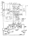
- FIG. 1 is a schematic diagram illustrating a yarn processing station and associated control circuitry in accordance with the present invention.
- the left hand portion of the diagram illustrates a yarn processing station, and wherein a yarn 10 is withdrawn from a supply roll or other source (not shown) by delivery roll 11.
- the yarn advances past a conventional yarn cutter 12, and then it is guided across and in contact with a heater 13, through a false twister 14, and past a yarn sensor 15.
- the yarn is withdrawn from the false twisting zone by delivery roll 16 and wound onto a package 17 by means of a conventional winder.
- the output signal U of the sensor 15 is transmitted to a circuit 20, which is illustrated within the dash-dot line of Figure 2.
- Circuit 20 is associated with each position of a multi-position false twist machine, and with the yarn sensor 15 of such position.
- the circuit 20 receives predetermined tolerance values from a set limit values memory 22 which is described below in more detail.
- Memory 22 is associated with a group of stations of the multi-position texturing machine.
- Circuit 20 produces one output signal to the yarn cutter 12 and another output signal to a general alarm unit 23 which is also associated with a group of stations.
- Circuit 20, furthermore, produces output signals to alarm unite 25, 26, 27, 28 which will be described below in more detail. These alarm units are correlated to the associated processing station.
- the output signal of yarn sensor 15 is fed to amplifier 30 and then to filter 32.
- the filter is a circuit containing an induction coil and a capacitor, the circuit having a delay time constant of for example one to three seconds.
- the output signal of the amplifier 30 is a voltage U which may be fed to a central microprocessor for further processing and calculation via line 34.
- the output of filter 32 is the mean value MU which may also be fed to a general microprocessor via line 35 for further processing and calculation.
- signal U and signal MU are fed to differential amplifier 38 producing an output signal DU which represents the difference of the input signals U and MU.
- the output signal DU of the differential amplifier 38 may be fed via line 36 to the central microprocessor for further processing and calculation.
- the output signal MU of the filter 32 is furthermore used to produce alarm signals A1 and A2, if the mean value MU leaves the predetermined range of tolerance.
- the predetermined range of tolerance is defined by the upper limit of the mean value UMU and by the lower limit of the mean value LMU, both of which are stored in the limit values memory 22 and fed to circuit 20 via respective lines.
- the circuit 20 for this purpose contains triggers 40 and 41.
- Trigger 40 is fed by the mean value MU and the upper limit of the mean value UMU, and it is designed to produce an output signal A1, if the mean value exceeds the set upper limit of the mean value.
- Trigger 41 is designed to receive the mean value MU and set lower limit of the mean value LMU as an input signal and to produce an output signal A2, if the mean value Mu is lower than the set lower limit of the mean value.
- the circuit 20 also produces alarm signals A3, A4, if the differential signal DU exceeds the predetermined range which is defined by a set upper limit of the differential value UDU and the set lower value of the differential value LDU.
- the predetermined upper and lower limits are stored in the limit values memory 22 and fed as input signals to triggers 42 and 43, respectively, of the circuit 20.
- the other input signal to the triggers 42 and 43 is the differential signal DU which is the output of differential amplifier 38 as described above. If the differential signal DU is greater than the set upper limit UDU, trigger 42 produces alarm signal A3. If differential value DU is smaller than the set lower limit LDU, trigger 43 produces alarm signal A4.
- Each of the alarm signals A1, A2, A3, A4 is fed to either one of the alarm units 25-28 which are associated with this position and which are, e.g., designed as a light emitting diode integrated into the circuit 20. Furthermore, alarm signals A1 to A4 are fed to OR gate 44, delay time unit 45, memory 46 and amplifier 47.
- the OR gate 44 produces an output signal, if any one of the alarm signals A1 to A4 is present.
- the delay time unit has a delay constant of about 10 msec, and is designed to prevent an output signal from a transient and irrelevant disturbance of the yarn texturing process, and which could result in the yarn 10 being cut by yarn cutter 12.
- the memory 46 ensures that a general alarm unit 23, which is associated with a group of stations or with the entire machine, will be able to generate a permanent signal to show that the production is disturbed and/or terminated.
- the output signal of the memory 46 is also fed to an amplifier 47 and from there to OR gate 48, which receives another signal to be more fully described below.
- the output signal of the amplifier 47 produces an output signal of the OR gate 48, which in turn is fed to the yarn cutter 12 to cause cutting of the yarn and interruption of the texturizing or draw-texturizing process, as the case may be.
- the other input signal to OR gate 48 is produced by trigger 49 via delay time unit 50 and amplifier 51.
- Trigger 49 is fed by the value U representing the measured yarn tension and by a second set value LU stored in set limit value memory 22 and representing the lowest accepted value of the yarn tension. It should be noted that this value LU is preferably set at zero.
- Trigger 49 produces an output signal, if the measured value U is lower than or equal to the set value LU.
- the delay time constant of unit 50 may be about 10 msec.
- the output signal of trigger 49 is, as mentioned above, fed to OR gate 48 and causes yarn cutter 12 to cut the yarn upstream of delivery roll 11, if and when the yarn tension is below a set value or in case of a yarn break between delivery rolls 11 and 16.
- the apparatus and circuit to the extent described above, generally conforms to that disclosed in the above noted U.S. patent to Martens, No. 4,720,702.
- an alarm signal A1-A4 is produced, when the continuously formed mean value of the measured value and the differential value between the continuously picked up measuring signal and the continuously formed mean value leave their respective tolerance ranges, which are predetermined separately for the mean value and for the differential value.
- these occurrences are counted and the number of the occurrences in a predetermined time SR results in a quality determining signal.
- the time period may, for example, be a winding cycle or a portion thereof.
- the quality signals QSM for the deviations of the mean values and the quality signals QSE for the deviations of the differential value from their respective tolerance ranges are determined and counted separately.
- a quality class or quality classes are determined, by the number QDSM or QDSE, respectively, of quality signals, occurred during the predetermined unit of time SR such as, for example, A-quality for 1 ⁇ QDSM ⁇ 10 and 1 ⁇ QDSE ⁇ 50 B-quality for 10 ⁇ QDSM or 50 ⁇ QDSE C-quality for 10 ⁇ QDSM and 50 ⁇ QDSE.
- the quality of a produced package is thus made dependent on the number of failures which have occurred.
- the failures may occur for different periods of time. The longer a failure occurs, the greater is the damaged yarn length. Consequently, it is possible and preferred to include in the quality evaluation not only the number but also the total duration of failures occurred during a predetermined period of time SR. To this end, the failure times may be summed, i.e., the failure times TM of the mean value faults to sum QLM on the one hand, and the failure times TD of the extreme value faults to the sum QLE on the other. Also these failure times may be used for the classification of quality, or, however, for an alarm or warning signal, or for interrupting a winding process when a preset time limit for QLM and/or QLE is exceeded.
- the alarm signals A1 to A4 are fed to OR gates 80 and 81, respectively. More particularly, alarm signals A1 and A2 representing the failure that the mean value has left its permitted range between the upper limiting value and the lower limiting value, are fed to OR gate 80, whereas the alarm signals A3, A4 representing the failure that the differential signal between the actual measured yarn tension and the mean value has left its predetermined range between the upper and the lower limiting values, are fed to OR gate 81.
- the output signals of the OR gates 80, 81 are fed via time measuring units 82 to storage means 83 and 84.
- Time measuring units 82.1 and 82.2 each have two other inputs.
- One of the inputs serves to store and preset a delay time TD.
- the delay time is the time between the first occurrence of an alarm signal A to time measuring units 82.1 and 82.2, and the first occurrence of the output signals QSM or QSE therefrom.
- the delay time TD can be set differently for each of the time measuring units.
- the other input of the time measuring units serves for storing a predetermined time of repetition TR. This time of repetition is a preset time, after which the output signal QSM or QSE of the time measuring unit is repeated, if the input signal A thereto lasts longer than said time of repetition TR. This means that every occurrence of a failure exceeding the delay time TD set in the time measuring units 82.1 and 82.2 will cause at least one quality signal QSM, QSE to be stored in either one of the storage means 83 or 84.
- Another signal QSM, QSE will be stored in the respective storage means 83 or 84, if an alarm signal fed to the time measuring unit after having been counted, lasts longer than the preset time of repetition TR. That means that each alarm signal causes a first quality signal QSM, QSE, if after its first occurrence the delay time TD has expired and causes a next quality signal QSM, QSE, if it still is present, when the time of repetition has expired after the previous count.
- Each of the storage means 83 and 84 has inputs for classification numbers A, B, and C.
- Each of the classification numbers represents a limited number of quality signals and also a quality classification number. So, for example, the input A may be 10, B may be 20, C may be 30. If the number of quality signals which are summed up in storage means 83 representing mean value faults is less than 10 per winding cycle of one package, the quality classification is A. If the number of failures is between 10 and 20, the quality is B. If the number of failures exceeds 20, the quality is C.
- Using two OR gates 80, 81 and storage means 83 and 84 each attributed to one kind of failures, it is possible to also classify the quality of the packages according to the kind of deficiencies they have, i.e.
- the output signals from storage means 83, 84 are fed to a marking device 85, for example, a printer for printing quality indicia for the package. It is evident that further criteria of quality classification may be derived from either one of the alarm signals or either group of the alarm signals A1 to A4.
- the output signal from OR gates 80, 81 are fed to integrating units 86, 87 measuring the time during which the respective output signal A of the OR gate 80 or 81 is present.
- the measured time also represents the yarn length which has been produced and wound up, while a respective one of a mean value failure or an extreme value failure was present.
- Each of the integrating units 86, 87 has an input for setting and storing a time limit or a yarn length limit LT. If the deficiency time DT stored to the integrating unit exceeds the set time limit LT, an output signal QLM or QLE is caused which may be fed to the marking device 85, showing that more than a permitted range of yarn length is of inferior quality.
- diagram I of Figure 2 represents a segment of a graph of yarn tension versus time with the yarn tension being indicated by an output signal U from a tension sensor as shown in Fig. 1.
- the mean value MU is shown in diagram II. The mean value is determined by supplying the tension signal U to an electrical filter having a relatively long time distance such as filter 32 in Fig. 1.
- Diagrams III to VI show the steps of quality evaluation with respect to the mean value faults as per this invention.
- the segment of the mean value during the time as represented by Diagram II exceeds one time the preset lower limit LMU and causes the alarm signal A2 and exceeds another time the upper limit UMU and causes the alarm signal A1 (see Fig. 1).
- the alarm signals A1 and A2 are fed to OR gate 81, the output of which causes time measuring device 82.1 to run. This is shown in Diagram IV.
- time measuring device 82.1 gives an output signal QSM represented in Diagram IV.
- the output signal QSM is repeated after a preset time interval TR. For example, that during alarm signal Al the first signal is generated after expiration of the delay time TD and four other signals QSM are generated each after expiration of one repetition interval TR.
- the QSM signals are fed to storage unit 84 for summing up all of the QSM signals to a quality determining signal for the mean value faults QDSM which is shown in Diagram V.
- the quality determining signal QSM exceeding one of the preset limits A, B, C determines the quality.
- the output signal of OR-gate 81 as shown in Diagram III is also fed to integrating device 86. Thereby, a quality signal is generated, a graph of which is shown in Diagram VI.
- This quality signal QLM is the total time during which one of the alarm signals A1, A2 was generated. As the yarn speed is constant, this signal QLM also corresponds to the length of yarn which was produced, while a mean value fault was present. This length of yarn is more or less damaged, and the length of yarn therefore also determines the quality. Therefore, the QLM signal is also fed to the printer 85.
- the measured yarn tension U and the mean value of the yarn tension as formed by filter 32 is also fed - as shown in Fig. 1 - to the triggers 42, 43 and a differential signal DU is formed.
- the segment of a graph shown in Diagram VII represents the difference DU between the measured value U and the mean value MU.
- this differential value DU sometimes exceeds the upper limit UDU and the lower limit LDU preset for the value DU. That means that the extreme value of the yarn tension represented by the output signal U exceeds a permitted range. Therefore, signals A3 or A4 are generated, respectively, representing such an extreme value fault.
- These alarm signals A3, A4, respectively, are shown in Diagram VIII.
- Alarm signals A3, A4 are fed via OR gate 80 to time measuring device 82.2.
- Time measuring device 82.2 has two inputs as described with reference to device 82.1.
- the inputs of time measuring device 82.2 can be set differently from that one of time measuring device 82.1. Performance, however, is identical and therefore reference is made to the above description.
- the time measuring device 82.2 gives a quality signal QSE after expiration of the delay time TD and furthermore another quality signal QSE after each interval TR for the whole time during which one of the alarm signals A3, A4 is present.
- Integrating device 83 sums up all of these quality signals QSE to the output signal QDSE determining the quality of the package with respect to extreme value faults occurred during the preset time SR.
- the signal QDSE is shown in Diagram X.
- the output signal of OR gate 80 can also be given to integrating device 87 for integrating the total time during which one of the alarm signals A3, A4 was present. Thereby a quality signal QLE is generated representing the length of yarn damaged by extreme value faults. This is shown in Diagram XI.
Landscapes
- Engineering & Computer Science (AREA)
- Chemical & Material Sciences (AREA)
- Textile Engineering (AREA)
- Health & Medical Sciences (AREA)
- Life Sciences & Earth Sciences (AREA)
- Physics & Mathematics (AREA)
- Food Science & Technology (AREA)
- Medicinal Chemistry (AREA)
- Quality & Reliability (AREA)
- Analytical Chemistry (AREA)
- Biochemistry (AREA)
- General Health & Medical Sciences (AREA)
- General Physics & Mathematics (AREA)
- Immunology (AREA)
- Pathology (AREA)
- Filamentary Materials, Packages, And Safety Devices Therefor (AREA)
- Spinning Or Twisting Of Yarns (AREA)
- Controlling Rewinding, Feeding, Winding, Or Abnormalities Of Webs (AREA)
Claims (8)
- Verfahren zur Überwachung der Fadenzugkraft eines laufenden Fadens mit ununterbrochener Überwachung des Wertes (U) der Fadenzugkraft des laufenden Fadens während ununterbrochener Bestimmung des Mittelwertes (MU) der überwachten Fadenzugkraft und ebenfalls während ununterbrochener Bestimmung der Differenz (DU) zwischen dem überwachtem Wert und dem Mittelwert, mit Erzeugung eines ersten Alarmsignals immer, wenn der Mittelwert (MU) einen vorgegebenen Toleranzbereich (UMU;LMU) für eine vorbestimmte Zeit verläßt, und bei dem ein zweites Alarmsignal immer dann erzeugt wird, wenn der Differenzwert (DU) einen zweiten vorgegebenen Toleranzbereich (UDU;LDU) für eine vorbestimmte Zeit verläßt,
gekennzeichnet durch
Erfassung des ersten und zweiten, während einer vorbestimmten Zeit (SR) auftretenden, Alarmsignals, zur Bestimmung einer Qualitätsangabe des Fadens. - Verfahren nach Anspruch 1,
dadurch gekennzeichnet, daß
die Erfassung die Erzeugung eines Qualitätssignals (QSM oder QSE) in vorbestimmten Wiederholintervallen (TR) einschließt, solange eines der ersten oder zweiten Alarmsignale vorliegt. - Verfahren nach Anspruch 1 oder 2,
dadurch gekennzeichnet, daß
die Zeiten, während denen das erste Alarmsignal vorliegt, zur Erzeugung eines ersten Qualitätssignals (QLM) und/oder die Zeiten, während denen das zweite Alarmsignal vorliegt, zur Erzeugung eines zweiten Qualitätssignals (QLE) aufsummiert werden, wobei das erste und zweite Qualitätssignal die Fadenlänge minderer Qualität repräsentieren. - Verfahren nach Anspruch 1,
dadurch gekennzeichnet, daß
die Erfassung das jeweilige Zählen der ersten und zweiten Alarmsignale beinhaltet und die Erzeugung eines Alarmsignals, wenn die Anzahl der ersten oder zweiten Alarmsignale eine jeweilige Grenzzahl übersteigt. - Verfahren nach Anspruch 1,
dadurch gekennzeichnet, daß laufende Faden auf eine Spule aufgewickelt wird, und daß die Spule mit Kennzeichnungen entsprechend der Summe der erfaßten Alarmsignale und damit entsprechend der Garnqualität bedruckt wird. - Fadenbearbeitungsmaschine,
mit Einrichtungen zur Überwachung der Fadenzugkraft eines laufenden Fadens und mit Sensoreinrichtungen zur ununterbrochenen Überwachung des Wertes (U) der Zugkraft des laufenden Fadens,
mit ersten Schalteinrichtungen, die mit den Sensoreinrichtungen zusammenwirken
zur ununterbrochenen Bestimmung des Mittelwertes (MU) der überwachten Fadenzugkraft, und zur ununterbrochenen Bestimmung der Differenz (D) zwischen dem überwachten Wert und dem Mittelwert, und zur Erzeugung eines ersten Alarmsignals, wenn der Mittelwert (MU) einen vorgegebenen Toleranzbereich (UMU; LMU) während einer vorbestimmten Zeit verläßt, und zur Erzeugung eines zweiten Alarmsignals, wenn die Differenz (D) einen zweiten vorgegebenen Toleranzbereich (UDU;LDU) für eine vorgegebene Zeit verläßt, gekennzeichnet durch
zweite Schaltkreiseinrichtungen zur Erfassung der Anzahl der, während einer vorbestimmten Zeit auftretenden, Alarmsignale, zur Bestimmung einer Qualitätsanzeige des Fadens. - Fadenbearbeitungsmaschine nach Anspruch 6,
dadurch gekennzeichnet, daß
der zweite Schaltkreis Mittel zum jeweiligen Zählen der ersten und zweiten Alarmsignale enthält und zur Erzeugung eines weiteren Alarmsignals, wenn eines oder beide der ersten und zweiten Alarmsignale einen vorgegebenen Grenzwert überschreitet. - Fadenbearbeitungsmaschine nach Anspruch 6,
gekennzeichnet durch
Mittel zum Aufwickeln des Fadens auf eine Spule und zum Drucken von Angaben gemäß der Summe der erfaßten Alarmsignale entsprechend der Qualität der Fadenspule.
Applications Claiming Priority (2)
| Application Number | Priority Date | Filing Date | Title |
|---|---|---|---|
| DE3922244 | 1989-07-06 | ||
| DE3922244 | 1989-07-06 |
Publications (2)
| Publication Number | Publication Date |
|---|---|
| EP0406736A1 EP0406736A1 (de) | 1991-01-09 |
| EP0406736B1 true EP0406736B1 (de) | 1993-08-11 |
Family
ID=6384436
Family Applications (1)
| Application Number | Title | Priority Date | Filing Date |
|---|---|---|---|
| EP90112524A Expired - Lifetime EP0406736B1 (de) | 1989-07-06 | 1990-06-30 | Verfahren und Vorrichtung zum Überwachen der Spannung und Qualität eines laufenden Fadens |
Country Status (4)
| Country | Link |
|---|---|
| US (1) | US5018390A (de) |
| EP (1) | EP0406736B1 (de) |
| DE (1) | DE69002709T2 (de) |
| ES (1) | ES2043190T3 (de) |
Families Citing this family (8)
| Publication number | Priority date | Publication date | Assignee | Title |
|---|---|---|---|---|
| TW354078U (en) * | 1991-01-17 | 1999-03-01 | Barmag Barmer Maschf | Apparatus for monitoring the tension of an advancing yarn |
| RU2073865C1 (ru) * | 1993-04-29 | 1997-02-20 | Бармаг АГ | Способ контроля движущейся нити |
| DE59403291D1 (de) * | 1993-09-21 | 1997-08-14 | Barmag Barmer Maschf | Verfahren zur Qualitätssteuerung bei der Herstellung einer Vielzahl von Fäden |
| EP0875479A1 (de) * | 1997-04-04 | 1998-11-04 | Schärer Schweiter Mettler AG | Verfahren zur Verbesserung des Spulprozesses und Spulstation zur Durchführung des Verfahrens |
| KR100690214B1 (ko) * | 1998-10-09 | 2007-03-12 | 바마크 악티엔게젤샤프트 | 실의 연속 처리 방법, 실의 연속 풀림 장치, 합성 다섬유 실의 직조 방법 및, 실의 직조 및 권취용 직조 기계 |
| SE9900792D0 (sv) * | 1999-03-03 | 1999-03-03 | Iro Patent Ag | Method for monitoring run/stop conditions of a yarn |
| JP3509756B2 (ja) * | 2001-01-17 | 2004-03-22 | 村田機械株式会社 | 糸条加工装置 |
| TWI302903B (en) * | 2003-02-05 | 2008-11-11 | Saurer Gmbh & Co Kg | Yarn withdrawal device |
Family Cites Families (8)
| Publication number | Priority date | Publication date | Assignee | Title |
|---|---|---|---|---|
| US3729635A (en) * | 1970-10-14 | 1973-04-24 | Lindly & Co | Yarn inspector |
| US3931938A (en) * | 1974-03-18 | 1976-01-13 | Toray Industries, Inc. | Method and apparatus for winding yarn into yarn package |
| CH572860A5 (de) * | 1974-07-15 | 1976-02-27 | Apag Apparatebau Ag | |
| CH661913A5 (de) * | 1983-08-19 | 1987-08-31 | Zellweger Uster Ag | Verfahren und vorrichtung zur gleichzeitigen ueberwachung der garnqualitaet an einer vielzahl gleichartiger ueberwachungsstellen einer textilmaschine. |
| EP0158192B1 (de) * | 1984-03-31 | 1991-06-05 | B a r m a g AG | Verfahren zur zentralen Erfassung von Messwerten einer Vielzahl von Messstellen |
| DE3666029D1 (en) * | 1985-03-28 | 1989-11-09 | Teijin Seiki Co Ltd | Monitor of abnormality in a yarn winding apparatus |
| CN1027926C (zh) * | 1985-07-03 | 1995-03-15 | 巴马格巴默机器制造股份公司 | 运转纱线的连续监控方法 |
| DE3716473A1 (de) * | 1987-05-16 | 1988-11-24 | Schlafhorst & Co W | Verfahren zum sortieren von kreuzspulen an einem spulautomaten |
-
1990
- 1990-06-01 US US07/532,217 patent/US5018390A/en not_active Expired - Lifetime
- 1990-06-30 ES ES90112524T patent/ES2043190T3/es not_active Expired - Lifetime
- 1990-06-30 EP EP90112524A patent/EP0406736B1/de not_active Expired - Lifetime
- 1990-06-30 DE DE90112524T patent/DE69002709T2/de not_active Expired - Fee Related
Also Published As
| Publication number | Publication date |
|---|---|
| EP0406736A1 (de) | 1991-01-09 |
| DE69002709D1 (de) | 1993-09-16 |
| ES2043190T3 (es) | 1993-12-16 |
| US5018390A (en) | 1991-05-28 |
| DE69002709T2 (de) | 1994-01-05 |
Similar Documents
| Publication | Publication Date | Title |
|---|---|---|
| US4720702A (en) | Method and apparatus for monitoring the tension of an advancing yarn | |
| DE3928417C2 (de) | Steueranlage für eine Spinnmaschine | |
| US3789595A (en) | Automatic control system for correcting textile machinery malfunctions from sensed and stored malfunction data | |
| US5018390A (en) | Method and apparatus for monitoring the tension and quality of an advancing yarn | |
| EP0648332B1 (de) | Verfahren zur überwachung eines laufenden fadens | |
| EP0406735B1 (de) | Verfahren und Vorrichtung zum Messen der Spannung eines bewegenden Fadens | |
| EP0495446B1 (de) | Verfahren und Vorrichtung zum Überwachen der Qualität eines falschdralltexturierten Garns | |
| CA1254279A (en) | Broken filament detector and system therefor | |
| JPS6141330A (ja) | オープンエンド精紡機 | |
| KR910003227B1 (ko) | 급사체의 판별 교환방법 | |
| US3220758A (en) | Yarn knotting device and control means | |
| US4384596A (en) | Means and method for sensing loom conditions indicative of potential fabric defects | |
| US4977331A (en) | Method of and apparatus for detecting the degree of filling of supply spools on a spinning or twisting frame | |
| US4534042A (en) | Method of and apparatus for the continuous monitoring and analysis of the operation of spinning units in an open-end spinning machine | |
| US5055829A (en) | Method and apparatus for monitoring yarn tension | |
| EP0439106B1 (de) | Verfahren und Vorrichtung zum Überwachen einer Fadenspannung | |
| US3648026A (en) | Data monitoring system | |
| US4513921A (en) | Method and apparatus for detecting fluctuations of monitoring standard of thread-knotting monitor in auto-winder | |
| US3995417A (en) | Process and apparatus for counting yarn breakages | |
| US3796094A (en) | Method and apparatus for continuously detecting abnormal cross-sectional areas in running tow | |
| EP0806503B1 (de) | Maschine zum Falschdrallzwirnen eines Zwirns | |
| US4934814A (en) | Method of and device for determining the quality of running yarns | |
| US3984060A (en) | Apparatus to test for the presence of one only thread in textile machines | |
| GB1325757A (en) | Data monitoring system | |
| JP3658522B2 (ja) | 断糸位置検出方法及び測定装置 |
Legal Events
| Date | Code | Title | Description |
|---|---|---|---|
| PUAI | Public reference made under article 153(3) epc to a published international application that has entered the european phase |
Free format text: ORIGINAL CODE: 0009012 |
|
| AK | Designated contracting states |
Kind code of ref document: A1 Designated state(s): CH DE ES FR GB IT LI |
|
| 17P | Request for examination filed |
Effective date: 19901212 |
|
| 17Q | First examination report despatched |
Effective date: 19920706 |
|
| ITF | It: translation for a ep patent filed | ||
| GRAA | (expected) grant |
Free format text: ORIGINAL CODE: 0009210 |
|
| AK | Designated contracting states |
Kind code of ref document: B1 Designated state(s): CH DE ES FR GB IT LI |
|
| ET | Fr: translation filed | ||
| REF | Corresponds to: |
Ref document number: 69002709 Country of ref document: DE Date of ref document: 19930916 |
|
| REG | Reference to a national code |
Ref country code: ES Ref legal event code: FG2A Ref document number: 2043190 Country of ref document: ES Kind code of ref document: T3 |
|
| PLBE | No opposition filed within time limit |
Free format text: ORIGINAL CODE: 0009261 |
|
| STAA | Information on the status of an ep patent application or granted ep patent |
Free format text: STATUS: NO OPPOSITION FILED WITHIN TIME LIMIT |
|
| 26N | No opposition filed | ||
| REG | Reference to a national code |
Ref country code: CH Ref legal event code: NV Representative=s name: BARMAG GMBH ENGINEERING & MANUFACTURING |
|
| REG | Reference to a national code |
Ref country code: GB Ref legal event code: IF02 |
|
| PGFP | Annual fee paid to national office [announced via postgrant information from national office to epo] |
Ref country code: GB Payment date: 20020610 Year of fee payment: 13 |
|
| PGFP | Annual fee paid to national office [announced via postgrant information from national office to epo] |
Ref country code: ES Payment date: 20020625 Year of fee payment: 13 |
|
| PG25 | Lapsed in a contracting state [announced via postgrant information from national office to epo] |
Ref country code: GB Free format text: LAPSE BECAUSE OF NON-PAYMENT OF DUE FEES Effective date: 20030630 |
|
| PG25 | Lapsed in a contracting state [announced via postgrant information from national office to epo] |
Ref country code: ES Free format text: LAPSE BECAUSE OF NON-PAYMENT OF DUE FEES Effective date: 20030701 |
|
| GBPC | Gb: european patent ceased through non-payment of renewal fee |
Effective date: 20030630 |
|
| REG | Reference to a national code |
Ref country code: ES Ref legal event code: FD2A Effective date: 20030701 |
|
| PGFP | Annual fee paid to national office [announced via postgrant information from national office to epo] |
Ref country code: CH Payment date: 20070626 Year of fee payment: 18 |
|
| PGFP | Annual fee paid to national office [announced via postgrant information from national office to epo] |
Ref country code: DE Payment date: 20070820 Year of fee payment: 18 |
|
| PGFP | Annual fee paid to national office [announced via postgrant information from national office to epo] |
Ref country code: IT Payment date: 20070628 Year of fee payment: 18 |
|
| PGFP | Annual fee paid to national office [announced via postgrant information from national office to epo] |
Ref country code: FR Payment date: 20070625 Year of fee payment: 18 |
|
| REG | Reference to a national code |
Ref country code: CH Ref legal event code: PL |
|
| REG | Reference to a national code |
Ref country code: FR Ref legal event code: ST Effective date: 20090228 |
|
| PG25 | Lapsed in a contracting state [announced via postgrant information from national office to epo] |
Ref country code: DE Free format text: LAPSE BECAUSE OF NON-PAYMENT OF DUE FEES Effective date: 20090101 |
|
| PG25 | Lapsed in a contracting state [announced via postgrant information from national office to epo] |
Ref country code: CH Free format text: LAPSE BECAUSE OF NON-PAYMENT OF DUE FEES Effective date: 20080630 Ref country code: LI Free format text: LAPSE BECAUSE OF NON-PAYMENT OF DUE FEES Effective date: 20080630 |
|
| PG25 | Lapsed in a contracting state [announced via postgrant information from national office to epo] |
Ref country code: IT Free format text: LAPSE BECAUSE OF NON-PAYMENT OF DUE FEES Effective date: 20080630 Ref country code: FR Free format text: LAPSE BECAUSE OF NON-PAYMENT OF DUE FEES Effective date: 20080630 |