EP0406735B1 - Verfahren und Vorrichtung zum Messen der Spannung eines bewegenden Fadens - Google Patents
Verfahren und Vorrichtung zum Messen der Spannung eines bewegenden Fadens Download PDFInfo
- Publication number
- EP0406735B1 EP0406735B1 EP90112523A EP90112523A EP0406735B1 EP 0406735 B1 EP0406735 B1 EP 0406735B1 EP 90112523 A EP90112523 A EP 90112523A EP 90112523 A EP90112523 A EP 90112523A EP 0406735 B1 EP0406735 B1 EP 0406735B1
- Authority
- EP
- European Patent Office
- Prior art keywords
- output signal
- yarn
- drift
- zero point
- tension
- Prior art date
- Legal status (The legal status is an assumption and is not a legal conclusion. Google has not performed a legal analysis and makes no representation as to the accuracy of the status listed.)
- Expired - Lifetime
Links
- 238000000034 method Methods 0.000 title claims description 23
- 238000012544 monitoring process Methods 0.000 claims description 9
- 230000001960 triggered effect Effects 0.000 claims 1
- 238000004804 winding Methods 0.000 description 12
- 238000010586 diagram Methods 0.000 description 4
- 230000000737 periodic effect Effects 0.000 description 3
- 230000003213 activating effect Effects 0.000 description 2
- 230000007547 defect Effects 0.000 description 2
- 238000004519 manufacturing process Methods 0.000 description 2
- 241001589086 Bellapiscis medius Species 0.000 description 1
- 101100532801 Caenorhabditis elegans sdn-1 gene Proteins 0.000 description 1
- 241000428199 Mustelinae Species 0.000 description 1
- 239000003990 capacitor Substances 0.000 description 1
- 230000002596 correlated effect Effects 0.000 description 1
- 230000000875 corresponding effect Effects 0.000 description 1
- 230000006698 induction Effects 0.000 description 1
- 238000005259 measurement Methods 0.000 description 1
- 230000001052 transient effect Effects 0.000 description 1
- 238000011144 upstream manufacturing Methods 0.000 description 1
Images

Classifications
-
- G—PHYSICS
- G01—MEASURING; TESTING
- G01L—MEASURING FORCE, STRESS, TORQUE, WORK, MECHANICAL POWER, MECHANICAL EFFICIENCY, OR FLUID PRESSURE
- G01L25/00—Testing or calibrating of apparatus for measuring force, torque, work, mechanical power, or mechanical efficiency
-
- B—PERFORMING OPERATIONS; TRANSPORTING
- B65—CONVEYING; PACKING; STORING; HANDLING THIN OR FILAMENTARY MATERIAL
- B65H—HANDLING THIN OR FILAMENTARY MATERIAL, e.g. SHEETS, WEBS, CABLES
- B65H59/00—Adjusting or controlling tension in filamentary material, e.g. for preventing snarling; Applications of tension indicators
- B65H59/40—Applications of tension indicators
-
- G—PHYSICS
- G01—MEASURING; TESTING
- G01L—MEASURING FORCE, STRESS, TORQUE, WORK, MECHANICAL POWER, MECHANICAL EFFICIENCY, OR FLUID PRESSURE
- G01L5/00—Apparatus for, or methods of, measuring force, work, mechanical power, or torque, specially adapted for specific purposes
- G01L5/04—Apparatus for, or methods of, measuring force, work, mechanical power, or torque, specially adapted for specific purposes for measuring tension in flexible members, e.g. ropes, cables, wires, threads, belts or bands
- G01L5/10—Apparatus for, or methods of, measuring force, work, mechanical power, or torque, specially adapted for specific purposes for measuring tension in flexible members, e.g. ropes, cables, wires, threads, belts or bands using electrical means
-
- B—PERFORMING OPERATIONS; TRANSPORTING
- B65—CONVEYING; PACKING; STORING; HANDLING THIN OR FILAMENTARY MATERIAL
- B65H—HANDLING THIN OR FILAMENTARY MATERIAL, e.g. SHEETS, WEBS, CABLES
- B65H2557/00—Means for control not provided for in groups B65H2551/00 - B65H2555/00
- B65H2557/60—Details of processes or procedures
- B65H2557/61—Details of processes or procedures for calibrating
-
- B—PERFORMING OPERATIONS; TRANSPORTING
- B65—CONVEYING; PACKING; STORING; HANDLING THIN OR FILAMENTARY MATERIAL
- B65H—HANDLING THIN OR FILAMENTARY MATERIAL, e.g. SHEETS, WEBS, CABLES
- B65H2701/00—Handled material; Storage means
- B65H2701/30—Handled filamentary material
- B65H2701/31—Textiles threads or artificial strands of filaments
Definitions
- the present invention relates to a method and apparatus for measuring the tension of an advancing yarn which is subject to periodic interruptions in its advance, and which is characterized by the ability to correct for any errors in the zero point output signal of the tension sensor.
- German patent 24 12 153 and the corresponding U.S. Patent No. 3,931,938, disclose a yarn winding process wherein the yarn tension is periodically detected by a sensor located at the edge of the area covered by the traverse motion of the yarn. The output of the sensor is compared with a preset desired value, and the difference is fed into a controller which acts upon a regulator for varying the speed of rotation of the winding spindle, thereby keeping the yarn tension at the desired value throughout the winding operation.
- a method and apparatus which includes the steps of continuously monitoring the tension of the advancing yarn with a sensor and so that the sensor produces an output signal representative of the tension, monitoring the output signal of the sensor whenever the yarn is interrupted to thereby produce a zero point output signal UOn upon each interruption, and storing each zero point output signal in a computer memory.
- Each zero point output signal UOn is compared with a previously generated zero output signal UOn-1 to determine a zero point drift D, and an alarm signal is generated when the drift D exceeds a predetermined limit value GD.
- the determined zero point drift D is stored in the computer memory, and the values of the drift D occurring after each of the interruptions are summed to define a drift sum SD.
- the drift sum is then compared to a predetermined drift sum limiting value GSD, and an alarm signal is generated when the drift sum exceeds the drift sum limiting value.
- the indicated output signal is preferably input as the zero point signal for the subsequent yarn advancing cycle.
- a periodic monitoring of the zero point is not performed during a continuous operation, but rather, the monitoring of the zero point during the operation is conducted in such a manner which allows recognition of errors in the system.
- FIG. 1 there is illustrated a typical recording of the tension of an advancing yarn which is being wound on a package.
- a yarn cutter is actuated, when the yarn tension drops for a certain short period of time below a predetermined lower limiting value.
- the yarn tension sensor and a subsequent computer which evaluates the tension signals, emit a signal to the yarn cutter, which precedes the yarn sensor.
- the operation of the yarn treatment or yarn production station and thus the yarn path are interrupted.
- This means that the output signal of the yarn sensor would have to return to its original value, i.e., zero, without any disturbing influences.
- the output signal of the sensor has not returned to zero after a first winding cycle, despite the absence of a yarn.
- the difference between the original zero point signal and the present output signal is indicated as the drift D1 of the zero point.
- the presently obtained output signal is input as the zero point signal for the following winding cycle, and is stored by the computer.
- the yarn tension is recorded on the basis of the newly set zero point.
- the zero point drifts D1, D2 ... Dn which occur during the course of the time are summed, and when the sum of the drifts SD exceed a certain, predetermined limiting value GSD, the computer emits a warning signal, which indicates a defect of the yarn station or respectively the sensor. A new adjustment of the yarn sensor will then become necessary.
- Each individual drift D1, D2 ...Dn is also monitored so that a certain, predetermined limiting value of the drift GD is not exceeded. Also in this case, the computer emits a warning signal, which indicates a defect of the yarn station or respectively the sensor.
- the limiting value of the drift can amount to 5 cN, and the limiting value of drift sum GSD to 20 cN.
- the readjustment of the zero point to the respective drift value preferably occurs only after a certain time T following the interruption of the yarn path.
- the output signal is stored as a new zero point which is present on the yarn sensor only after a certain time T following the interruption of the yarn path. This period of time T may, for example, be 30 seconds. It is thus ensured that the yarn tension sensor reaches first its steady state condition, and that short-time interferences, which may, for example, be produced by servicing, do not enter into the zero point adjustment.
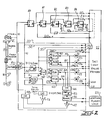
- FIG. 2 is a schematic diagram illustrating a yarn processing station and associated control circuitry in accordance with the present invention.
- the left hand portion of the diagram illustrates one yarn processing station of a multi-position false twist machine, and wherein a yarn 10 is withdrawn from a supply roll or other source (not shown) by delivery roll 11.
- the yarn advances past a conventional yarn cutter 12, and then it is guided across and in contact with a heater 13, through a false twister 14, and past a yarn sensor 15.
- the yarn is withdrawn from the false twisting zone by delivery roll 16 and wound onto a package 17 by means of a conventional winder.
- the output signal U of the sensor 15 is transmitted to a circuit 20, which is illustrated within the dash-dot line of figure 2.
- Circuit 20 is associated with each position of the multi-position false twist machine, and with the yarn sensor 15 of such position.
- the circuit 20 receives predetermined tolerance values from a set limit values memory 22 which is described below in more detail.
- Memory 22 is associated with a group of stations of the multi-position texturing machine.
- Circuit 20 produces one output signal to the yarn cutter 12 and another output signal to a general alarm unit 23 which is also associated with a group of stations.
- Circuit 20, furthermore, produces output signals to alarm units 25, 26, 27, 28 which will be described below in more detail. These alarm units are correlated to the associated processing station.
- the output signal of yarn sensor 15 is fed to amplifier 30 and then to filter 32.
- the filter is a circuit containing an induction coil and a capacitor, the circuit having a delay time constant of for example one to three seconds.
- the output signal of the amplifier 30 is a voltage U which may be fed to a central microprocessor for further processing and calculation via line 34.
- the output of filter 32 is the mean value MU which may also be fed to a general microprocessor via line 35 for further processing and calculation.
- signal U and signal MU are fed to differential amplifier 38 producing an output signal DU which represents the difference of the input signals U and MU.
- the output signal DU of the differential amplifier 38 may be fed via line 36 to the central microprocessor for further processing and calculation.
- the output signal MU of the filter 32 is furthermore used to produce alarm signals A1 and A2, if the mean value MU leaves the predetermined range of tolerance.
- the predetermined range of tolerance is defined by the upper limit of the mean value UMU and by the lower limit of the mean value LMU, both of which are stored in the limit values memory 22 and fed to circuit 20 via respective lines.
- the circuit 20 for this purpose contains triggers 40 and 41.
- Trigger 40 is fed by the mean value MU and the upper limit of the mean value UMU, and it is designed to produce an output signal A1, if the mean value exceeds the set upper limit of the mean value.
- Trigger 41 is designed to receive the mean value MU and set lower limit of the mean value LMU as an input signal and to produce an output signal A2, if the mean value MU is lower than the set lower limit of the mean value.
- the circuit 20 also produces alarm signals A3, A4, if the differential signal DU exceeds the predetermined range which is defined by a set upper limit of the differential value UDU and the set lower value of the differential value LDU.
- the predetermined upper and lower limits are stored in the limit values memory 22 and fed as input signals to triggers 42 and 43, respectively, of the circuit 20.
- the other input signal to the triggers 42 and 43 is the differential signal DU which is the output of differential amplifier 38 as described above. If the differential signal DU is greater than the set upper limit UDU, trigger 42 produces alarm signal A3. If differential value DU is smaller than the set lower limit LDU, trigger 43 produces alarm signal A4.
- Each of the alarm signals A1, A2, A3, A4 is fed to either one of the alarm units 25-28 which are associated with this position and which are, e.g., designed as a light emitting diode integrated into the circuit 20. Furthermore, alarm signals A1 to A4 are fed to OR gate 44, delay time unit 45, memory 46 and amplifier 47.
- the OR gate 44 produces an output signal, if any one of the alarm signals A1 to A4 is present.
- the delay time unit has a delay constant of about 10 msec, and is designed to prevent an output signal from a transient and irrelevant disturbance of the yarn texturing process, and which could result in the yarn 10 being cut by yarn cutter 12.
- the memory 46 ensures that a general alarm unit 23, which is associated with a group of stations or with the entire machine, will be able to generate a permanent signal to show that the production is disturbed and/or terminated.
- the output signal of the memory 46 is also fed to an amplifier 47 and from there to OR gate 48, which receives another signal to be more fully described below.
- the output signal of the amplifier 47 produces an output signal of the OR gate 48, which in turn is fed to the yarn cutter 12 to cause cutting of the yarn and interruption of the texturizing or draw-texturizing process, as the case may be.
- the other input signal to OR gate 48 is produced by trigger 49 via delay time unit 50 and amplifier 51.
- Trigger 49 is fed by the value U representing the measured yarn tension and by a second set value LU stored in set limit values memory 22 and representing the lowest accepted value of the yarn tension. It should be noted that this value LU is preferably set at zero.
- Trigger 49 produces an output signal, if the measured value U is lower than or equal to the set value LU.
- the delay time constant of unit 50 may be about 10 msec.
- the output signal of trigger 49 is, as mentioned above, fed to OR gate 48 and causes yarn cutter 12 to cut the yarn upstream of delivery roll 11, if and when the yarn tension is below a set value or in case of a yarn break between delivery rolls 11 and 16.
- the signal activating the cutter 12 from the OR gate 48, and the signal U from the sensor 15 are fed to an AND gate 80 delivering an output signal, if both the activating signal for the cutter 12 as well the output signal U from the sensor 15 are present.
- the output signal of gate 80 accordingly is equal to the output signal of the sensor 15, if no yarn is present.
- This output signal of gate 80 is called the zero-signal UOn.
- the zero-signal is delivered to the set limit values memory 22 and, furthermore, to a gate 81.
- Gate 81 has another input connected to the memory 22.
- Gate 81 forms the difference Dn between the new zero-signal UOn and the old zero-signal UOn-1 as an output signal.
- This difference Dn is stored in the memory 22.
- the difference Dn is fed to a trigger 82, with the other input being a predetermined limit value GD which has been previously stored in the computer memory 22. If the difference Dn exceeds the limit value GD, an alarm is actuated.
- the difference Dn is also fed to a further AND gate 83.
- the other input of AND gate 83 is the so-called old sum of the difference SDn-1 which has been stored in the memory 22 during occurrence of the previous yarn cuts.
- the output of gate 83 accordingly is the sum SD of all the differences D1 to Dn which have occurred up to the present yarn cut.
- the sum SD is also stored to the memory 22.
- a trigger 84 having two inputs, one of which is the output of preceding gate 82, i.e. the actual sum of differences, and the other input is a limit value GSD representing the maximum allowed sum of differences. If the actual sum of differences is greater than the allowed sum of differences, an alarm is given to the general alarm unit 23.
- the zero-signal UOn will be the basis, i.e. the zero point of tension measurement during the next winding cycle and may also be set in the memory 22 as the lowest accepted value LU of yarn tension.
Landscapes
- Physics & Mathematics (AREA)
- General Physics & Mathematics (AREA)
- Filamentary Materials, Packages, And Safety Devices Therefor (AREA)
- Spinning Or Twisting Of Yarns (AREA)
Claims (10)
- Verfahren zur Messung der Spannung eines laufenden Fadens, der auf seinem Weg Unterbrechungen ausgesetzt ist, mit der Möglichkeit, NULL-Punkt-Abweichungen des Ausgangssignals des Spannungssensors zu berichtigen,
gekennzeichnet durch
die Schritte
der ununterbrochenen Überwachung der Spannung des laufenden Fadens mit einem Sensor derart, daß der Sensor ein die Spannung repräsentierendes Ausgangssignal erzeugt,
der Überwachung des Ausgangssignals des Sensors, sobald der Fadenlauf unterbrochen ist, um hierdurch nach jeder Unterbrechung ein NULL-Punkt-Ausgangssignal (UOn) zu erzeugen , und der Speicherung jedes NULL-Punkt-Ausgangssignals in einem elektronischen Speicher,
des Vergleichens jedes NULL-Punkt-Ausgangssignals (UOn) mit einem vorher erzeugten NULL-Ausgangssignal (UOn-1) zur Berechnung einer NULL-Punkt-Abweichung (D) und der Erzeugung eines Alarmsignals, sobald die Abweichung (D) einen vorgegebenen Grenzwert (GD) übersteigt. - Verfahren nach Anspruch 1,
gekennzeichnet durch
den weiteren Schritt, daß nach jeder Unterbrechung des Fadenlaufs das angezeigte Ausgangssignal als das NULL-Punkt-Signal des nachfolgenden Fadenlaufzyklus zurückgeführt wird. - Verfahren nach Anspruch 1,
dadurch gekennzeichnet, daß
die Speicherung jedes NULL-Punkt-Ausgangssignals um einen, zur Erzielung eines stationären Zustands des Sensors, vorbestimmten Zeitabschnitt verzögert ist. - Verfahren zur Messung der Spannung eines laufenden Fadens, der auf seinem Weg Unterbrechungen ausgesetzt ist, mit der Möglichkeit zur Berichtigung irgendwelcher NULL-Punkt-Abweichungen des-Ausgangssignals des Spannungssensors,
gekennzeichnet durch
ununterbrochene Überwachung der Spannung des laufenden Fadens mit einem Sensor derart, daß der Sensor ein die Spannung repräsentierendes Ausgangssignal erzeugt,
Überwachung des Ausgangssignals des Sensors immer wenn der Fadenlauf unterbrochen ist, um hierdurch nach jeder Unterbrechung ein NULL-Punkt-Ausgangssignal (UOn) zu erzeugen und der Speicherung jedes NULL-Punkt-Ausgangssignals in einem elektronischen Speicher,
Vergleich jedes NULL-Punkt-Ausgangssignals (UOn) mit einem vorher erzeugten NULL-Ausgangssignal (UOn-1) zur Berechnung einer NULL-Punkt-Abweichung (D) und Speicherung dieser Abweichung in einem elektronischen Speicher,
Aufsummieren der Werte der Abweichung (D) nach jeder der Unterbrechungen des Fadenlaufs zur Festlegung einer Abweichungssumme (SD), Vergleich der Abweichungssumme mit einem vorgegebenen Abweichungssummengrenzwert (SD) und Erzeugung eines Alarmsignals, sobald die Abweichungssumme den Abweichungssummengrenzwert übersteigt. - Verfahren nach Anspruch 4,
dadurch gekennzeichnet, daß
der Vergleich jedes NULL-Punkt-Ausgangssignals mit dem vorher erzeugten NULL-Ausgangssignal mit der Erzeugung eines weiteren Alarmsignals erfolgt, sobald die Abweichung (D) einen vorgegebenen Grenzwert (GD) übersteigt. - Verfahren nach Anspruch 4,
dadurch gekennzeichnet, daß
bei Unterbrechung des Fadenlaufs die Trennung des Fadens durch Betätigung eines Fadenmessers erfolgt. - Verfahren nach Anspruch 6,
dadurch gekennzeichnet, daß
die Trennung des Fadens durch Triggerung erfolgt, sobald das Ausgangssignal des Sensors unter einen vorbestimmten unteren Grenzwert (LU) fällt. - Verfahren nach Anspruch 4,
dadurch gekennzeichnet, daß
die Speicherung jedes NULL-Punkt-Ausgangssignals und die Speicherung der Abweichung jeweils in einem elektronischen Speicher mit Verzögerung für einen vorbestimmten Zeitabschnitt nach Unterbrechung des Fadenlaufs zur Erzielung eines stationären Sensorzustands erfolgt. - Verfahren nach Anspruch 4,
dadurch gekennzeichnet, daß
nach jeder Unterbrechung des Fadenlaufs das angezeigte Ausgangssignal das NULL-Punkt-Signal des nachfolgenden Fadenlaufzyklus ist. - Vorrichtung zur Messung der Spannung eines laufenden Fadens, der Unterbrechungen in seinem Lauf durch Trennung ausgesetzt ist, mit einem Sensor zur ununterbrochenen Überwachung der Spannung des laufenden Fadens derart, daß ein die Spannung repräsentierendes Ausgangssignal erzeugt wird, und derart, daß nach jeder Trennung des laufenden Fadens ein NULL-Punkt-Ausgangssignal (UOn) von einem erzeugten Ausgangssignal definiert wird,
gekennzeichnet durch
elektronische Speichereinrichtungen zum Speichern jedes NULL-Punkt-Ausgangssignals,
erste Schalteinrichtungen zum Vergleich jedes NULL-Punkt-Ausgangssignals (UOn) mit einem vorangegangen erzeugten NULL-Ausgangssignal (UOn-1) zur Berechnung einer NULL-Punkt-Abweichung (D), mit Mitteln zur Speicherung dieser Abweichung in besagtem elektronischen Speicher und mit Mitteln zur Erzeugung eines Alarmsignals, sobald die Abweichung einen vorgegebenen Grenzwert (GD) übersteigt und mit
zweiten Schalteinrichtungen zur Aufsummierung der Abweichungswerte (D) nach jeder Trennung des Fadens zur Erzeugung einer Abweichungssumme (SD), und mit Mitteln zum Vergleich der Abweichungssumme mit einem vorgegebenen Abweichungssummengrenzwert (GSD) und mit Mitteln zur Erzeugung eines weiteren Alarmsignals, wenn die Abweichungssumme den Abweichungssummengrenzwert übersteigt.
Applications Claiming Priority (2)
| Application Number | Priority Date | Filing Date | Title |
|---|---|---|---|
| DE3922245 | 1989-07-06 | ||
| DE3922245 | 1989-07-06 |
Publications (3)
| Publication Number | Publication Date |
|---|---|
| EP0406735A2 EP0406735A2 (de) | 1991-01-09 |
| EP0406735A3 EP0406735A3 (en) | 1991-12-27 |
| EP0406735B1 true EP0406735B1 (de) | 1993-10-06 |
Family
ID=6384437
Family Applications (1)
| Application Number | Title | Priority Date | Filing Date |
|---|---|---|---|
| EP90112523A Expired - Lifetime EP0406735B1 (de) | 1989-07-06 | 1990-06-30 | Verfahren und Vorrichtung zum Messen der Spannung eines bewegenden Fadens |
Country Status (4)
| Country | Link |
|---|---|
| US (1) | US5017911A (de) |
| EP (1) | EP0406735B1 (de) |
| DE (1) | DE69003750T2 (de) |
| TW (1) | TW203634B (de) |
Cited By (3)
| Publication number | Priority date | Publication date | Assignee | Title |
|---|---|---|---|---|
| DE19806752B4 (de) * | 1998-02-18 | 2004-03-25 | Conti Temic Microelectronic Gmbh | Offsetregelung |
| WO2015188883A1 (en) | 2014-06-13 | 2015-12-17 | Memminger-Iro Gmbh | Method to control feeding a yarn and yarn feeder |
| DE102015120264B3 (de) * | 2015-11-23 | 2016-12-29 | Memminger-Iro Gmbh | Verfahren zur Steuerung der Fadenlieferung mindestens eines Fadenliefergerätes und Textilmaschine mit einem System mit mindestens einem Fadenliefergerät |
Families Citing this family (11)
| Publication number | Priority date | Publication date | Assignee | Title |
|---|---|---|---|---|
| US5136499A (en) * | 1986-07-07 | 1992-08-04 | Rydborn S A O | Monitoring for distinguishing normal from abnormal deviations in a knitting machine |
| US5682146A (en) * | 1993-04-29 | 1997-10-28 | Barmag Ag | Method of monitoring an advancing yarn |
| US5844494A (en) * | 1993-04-29 | 1998-12-01 | Barmag Ag | Method of diagnosing errors in the production process of a synthetic filament yarn |
| EP0644282B1 (de) * | 1993-09-21 | 1997-07-09 | B a r m a g AG | Verfahren zur Qualitätssteuerung bei der Herstellung einer Vielzahl von Fäden |
| DE19811241A1 (de) * | 1998-03-14 | 1999-09-30 | Memminger Iro Gmbh | Fadenspannungssensor mit wiederholtem Abgleich |
| DE19940161A1 (de) * | 1999-08-25 | 2001-03-01 | Schlafhorst & Co W | Vorrichtung zum Abgleich eines Fadenzugkraftsensors |
| DE10119600A1 (de) | 2001-04-21 | 2002-10-31 | Bosch Gmbh Robert | Einrichtung und Verfahren zur Kalibrierung eines Sensors |
| GB0815038D0 (en) * | 2008-08-18 | 2008-09-24 | Seaman Peter | Improvements in or relating to analysing structual memebers |
| DE102013009452A1 (de) * | 2013-06-06 | 2014-12-11 | Saurer Germany Gmbh & Co. Kg | Nullpunktabgleich eines Fadenzugkraftsensors |
| DE102013009652A1 (de) * | 2013-06-08 | 2014-12-11 | Saurer Germany Gmbh & Co. Kg | Verfahren zum Einstellen einer Drehwinkelstellung eines eine Spule drehbeweglich halternden Spulenrahmens, Spulen herstellende Textilmaschine mit mehreren Spulstellen und Verwendung eines einen Spulenrahmen antreibenden Schrittmotors |
| WO2020201936A1 (en) * | 2019-03-30 | 2020-10-08 | Lohia Corp Limited | A system and method to monitor tape breakage |
Family Cites Families (8)
| Publication number | Priority date | Publication date | Assignee | Title |
|---|---|---|---|---|
| US3931938A (en) * | 1974-03-18 | 1976-01-13 | Toray Industries, Inc. | Method and apparatus for winding yarn into yarn package |
| ES8302594A1 (es) * | 1982-03-04 | 1983-01-16 | Empresa Nac Hulleras Norte | "equipo para control de cables-guia". |
| DE3583057D1 (de) * | 1984-03-31 | 1991-07-11 | Barmag Barmer Maschf | Verfahren zur zentralen erfassung von messwerten einer vielzahl von messstellen. |
| GB2169928B (en) * | 1985-01-19 | 1988-05-11 | Rieter Scragg Ltd | Monitoring the tension of yarn drawn off from a package |
| DE3666029D1 (en) * | 1985-03-28 | 1989-11-09 | Teijin Seiki Co Ltd | Monitor of abnormality in a yarn winding apparatus |
| CN1027926C (zh) * | 1985-07-03 | 1995-03-15 | 巴马格巴默机器制造股份公司 | 运转纱线的连续监控方法 |
| EP0240074A3 (de) * | 1986-04-02 | 1989-09-20 | Picanol N.V. | Vorrichtung zur Prüfung von Garnen |
| DE3708565A1 (de) * | 1987-03-17 | 1988-09-29 | Kugelfischer G Schaefer & Co | Verfahren und vorrichtung zum messen einer fadenzugkraft |
-
1990
- 1990-06-04 US US07/532,340 patent/US5017911A/en not_active Expired - Lifetime
- 1990-06-07 TW TW080107865A patent/TW203634B/zh active
- 1990-06-30 EP EP90112523A patent/EP0406735B1/de not_active Expired - Lifetime
- 1990-06-30 DE DE90112523T patent/DE69003750T2/de not_active Expired - Fee Related
Cited By (5)
| Publication number | Priority date | Publication date | Assignee | Title |
|---|---|---|---|---|
| DE19806752B4 (de) * | 1998-02-18 | 2004-03-25 | Conti Temic Microelectronic Gmbh | Offsetregelung |
| WO2015188883A1 (en) | 2014-06-13 | 2015-12-17 | Memminger-Iro Gmbh | Method to control feeding a yarn and yarn feeder |
| TWI568903B (zh) * | 2014-06-13 | 2017-02-01 | 美名格 艾羅有限公司 | 控制喂紗之方法及喂紗器 |
| DE102015120264B3 (de) * | 2015-11-23 | 2016-12-29 | Memminger-Iro Gmbh | Verfahren zur Steuerung der Fadenlieferung mindestens eines Fadenliefergerätes und Textilmaschine mit einem System mit mindestens einem Fadenliefergerät |
| EP3170779A1 (de) | 2015-11-23 | 2017-05-24 | Memminger-IRO GmbH | Verfahren zur steuerung der fadenlieferung mindestens eines fadenliefergerätes und textilmaschine mit einem system mit mindestens einem fadenliefergerät |
Also Published As
| Publication number | Publication date |
|---|---|
| EP0406735A3 (en) | 1991-12-27 |
| DE69003750D1 (de) | 1993-11-11 |
| DE69003750T2 (de) | 1994-03-03 |
| EP0406735A2 (de) | 1991-01-09 |
| US5017911A (en) | 1991-05-21 |
| TW203634B (de) | 1993-04-11 |
Similar Documents
| Publication | Publication Date | Title |
|---|---|---|
| US4720702A (en) | Method and apparatus for monitoring the tension of an advancing yarn | |
| EP0406735B1 (de) | Verfahren und Vorrichtung zum Messen der Spannung eines bewegenden Fadens | |
| US4667889A (en) | Stepped precision winding process | |
| TWI512157B (zh) | 探測從設有固定轉筒的紗線饋送器停止展開紗線的方法 | |
| CN101268001B (zh) | 操作生产染色筒子的纺纱机的工位的方法 | |
| EP0648332B1 (de) | Verfahren zur überwachung eines laufenden fadens | |
| EP0495446B1 (de) | Verfahren und Vorrichtung zum Überwachen der Qualität eines falschdralltexturierten Garns | |
| JPH05138277A (ja) | コイルばねの製造方法 | |
| JPS6141330A (ja) | オープンエンド精紡機 | |
| US4998003A (en) | Electrical discharge wire-cutting machine | |
| US3792821A (en) | Apparatus for combining linear bodies into a composite product | |
| EP0406736B1 (de) | Verfahren und Vorrichtung zum Überwachen der Spannung und Qualität eines laufenden Fadens | |
| US5055829A (en) | Method and apparatus for monitoring yarn tension | |
| EP0112920B1 (de) | Verfahren und vorrichtung zur feststellung von schwankungen des überwachungsstandards der garnverbindekontrolleinheit in einer automatischen aufspulmaschine | |
| EP0439106B1 (de) | Verfahren und Vorrichtung zum Überwachen einer Fadenspannung | |
| EP3947793B1 (de) | Verfahren zur kontaktlosen optischen erfassung von garn an einer arbeitsstelle einer garnherstellungstextilmaschine, optischer garnsensor und textilmaschine | |
| JP2688265B2 (ja) | 給糸ボビンの給糸特性を検出する方法および装置 | |
| US3995417A (en) | Process and apparatus for counting yarn breakages | |
| US4012816A (en) | Method and apparatus for processing thermoplastic yarn | |
| EP0806503B1 (de) | Maschine zum Falschdrallzwirnen eines Zwirns | |
| KR100336861B1 (ko) | 와이어 제품 권취기의 자동 권취 방법 및 장치 | |
| EP1024213B1 (de) | Verfahren zur Behandlung einer Falschdraht-Verwindung | |
| JP3810561B2 (ja) | 糸条の張力検出方法及び装置 | |
| EP4261331A1 (de) | Zwirneinheit mit einem eigenständigen fadenbruchkontrollsensor und verfahren zur erkennung des bruchs eines verdrillten fadens | |
| JP3658522B2 (ja) | 断糸位置検出方法及び測定装置 |
Legal Events
| Date | Code | Title | Description |
|---|---|---|---|
| PUAI | Public reference made under article 153(3) epc to a published international application that has entered the european phase |
Free format text: ORIGINAL CODE: 0009012 |
|
| AK | Designated contracting states |
Kind code of ref document: A2 Designated state(s): CH DE ES FR GB IT LI |
|
| PUAL | Search report despatched |
Free format text: ORIGINAL CODE: 0009013 |
|
| AK | Designated contracting states |
Kind code of ref document: A3 Designated state(s): CH DE ES FR GB IT LI |
|
| 17P | Request for examination filed |
Effective date: 19911205 |
|
| 17Q | First examination report despatched |
Effective date: 19930309 |
|
| ITF | It: translation for a ep patent filed |
Owner name: DE DOMINICIS & MAYER S.R.L. |
|
| GRAA | (expected) grant |
Free format text: ORIGINAL CODE: 0009210 |
|
| AK | Designated contracting states |
Kind code of ref document: B1 Designated state(s): CH DE ES FR GB IT LI |
|
| PG25 | Lapsed in a contracting state [announced via postgrant information from national office to epo] |
Ref country code: ES Free format text: THE PATENT HAS BEEN ANNULLED BY A DECISION OF A NATIONAL AUTHORITY Effective date: 19931006 |
|
| REF | Corresponds to: |
Ref document number: 69003750 Country of ref document: DE Date of ref document: 19931111 |
|
| ET | Fr: translation filed | ||
| PLBE | No opposition filed within time limit |
Free format text: ORIGINAL CODE: 0009261 |
|
| STAA | Information on the status of an ep patent application or granted ep patent |
Free format text: STATUS: NO OPPOSITION FILED WITHIN TIME LIMIT |
|
| 26N | No opposition filed | ||
| REG | Reference to a national code |
Ref country code: CH Ref legal event code: NV Representative=s name: BARMAG GMBH ENGINEERING & MANUFACTURING |
|
| PGFP | Annual fee paid to national office [announced via postgrant information from national office to epo] |
Ref country code: GB Payment date: 20010612 Year of fee payment: 12 |
|
| REG | Reference to a national code |
Ref country code: GB Ref legal event code: IF02 |
|
| PG25 | Lapsed in a contracting state [announced via postgrant information from national office to epo] |
Ref country code: GB Free format text: LAPSE BECAUSE OF NON-PAYMENT OF DUE FEES Effective date: 20020630 |
|
| GBPC | Gb: european patent ceased through non-payment of renewal fee |
Effective date: 20020630 |
|
| PGFP | Annual fee paid to national office [announced via postgrant information from national office to epo] |
Ref country code: FR Payment date: 20030618 Year of fee payment: 14 |
|
| PGFP | Annual fee paid to national office [announced via postgrant information from national office to epo] |
Ref country code: CH Payment date: 20030701 Year of fee payment: 14 |
|
| PGFP | Annual fee paid to national office [announced via postgrant information from national office to epo] |
Ref country code: DE Payment date: 20030704 Year of fee payment: 14 |
|
| PG25 | Lapsed in a contracting state [announced via postgrant information from national office to epo] |
Ref country code: LI Free format text: LAPSE BECAUSE OF NON-PAYMENT OF DUE FEES Effective date: 20040630 Ref country code: CH Free format text: LAPSE BECAUSE OF NON-PAYMENT OF DUE FEES Effective date: 20040630 |
|
| PG25 | Lapsed in a contracting state [announced via postgrant information from national office to epo] |
Ref country code: DE Free format text: LAPSE BECAUSE OF NON-PAYMENT OF DUE FEES Effective date: 20050101 |
|
| REG | Reference to a national code |
Ref country code: CH Ref legal event code: PL |
|
| PG25 | Lapsed in a contracting state [announced via postgrant information from national office to epo] |
Ref country code: FR Free format text: LAPSE BECAUSE OF NON-PAYMENT OF DUE FEES Effective date: 20050228 |
|
| REG | Reference to a national code |
Ref country code: FR Ref legal event code: ST |
|
| PG25 | Lapsed in a contracting state [announced via postgrant information from national office to epo] |
Ref country code: IT Free format text: LAPSE BECAUSE OF NON-PAYMENT OF DUE FEES;WARNING: LAPSES OF ITALIAN PATENTS WITH EFFECTIVE DATE BEFORE 2007 MAY HAVE OCCURRED AT ANY TIME BEFORE 2007. THE CORRECT EFFECTIVE DATE MAY BE DIFFERENT FROM THE ONE RECORDED. Effective date: 20050630 |