EP0406421A1 - Installation de traitement thermique de matieres polydispersees - Google Patents
Installation de traitement thermique de matieres polydispersees Download PDFInfo
- Publication number
- EP0406421A1 EP0406421A1 EP89904299A EP89904299A EP0406421A1 EP 0406421 A1 EP0406421 A1 EP 0406421A1 EP 89904299 A EP89904299 A EP 89904299A EP 89904299 A EP89904299 A EP 89904299A EP 0406421 A1 EP0406421 A1 EP 0406421A1
- Authority
- EP
- European Patent Office
- Prior art keywords
- polydisperse
- polydisperse material
- heat transfer
- transfer medium
- cyclone separator
- Prior art date
- Legal status (The legal status is an assumption and is not a legal conclusion. Google has not performed a legal analysis and makes no representation as to the accuracy of the status listed.)
- Withdrawn
Links
Images


Classifications
-
- F—MECHANICAL ENGINEERING; LIGHTING; HEATING; WEAPONS; BLASTING
- F26—DRYING
- F26B—DRYING SOLID MATERIALS OR OBJECTS BY REMOVING LIQUID THEREFROM
- F26B17/00—Machines or apparatus for drying materials in loose, plastic, or fluidised form, e.g. granules, staple fibres, with progressive movement
- F26B17/10—Machines or apparatus for drying materials in loose, plastic, or fluidised form, e.g. granules, staple fibres, with progressive movement with movement performed by fluid currents, e.g. issuing from a nozzle, e.g. pneumatic, flash, vortex or entrainment dryers
- F26B17/108—Machines or apparatus for drying materials in loose, plastic, or fluidised form, e.g. granules, staple fibres, with progressive movement with movement performed by fluid currents, e.g. issuing from a nozzle, e.g. pneumatic, flash, vortex or entrainment dryers using impinging streams of entrained material
Definitions
- the present invention relates to the heat treatment of substances and relates in particular to plants for the heat treatment of a polydisperse material.
- a plant for drying a polydisperse material is widely known (Express-informatsia. Zarubezhny opyt ", Tsintikhimneftemash, Series XM-I, No. 6, 1985, Tamir A., Elperin I., Lussatto K.”
- Convection dryer with counter-rotating beams ", S. 5 to 9) which contains a cylindrical drying chamber of the cyclone type, channels for supplying a heat transfer medium and the polydisperse material, which are connected to a feed device for polydisperse wet material and are attached tangentially to the side wall of the drying chamber.
- the system also contains a static swirler, which is in the form of helical plates which are formed between the side wall of the drying chamber and the side wall of one in the space of the drying chamber underfolded blow-out pipe are consolidated.
- the flows of the floating mixture of gas and polydisperse are fed tangentially to the collision zone on the cylindrical surface of the drying chamber, in which a centrifugal force field acts on the flows of the polydisperse.
- the particles of the polydisperse material move mainly on the side wall of the drying chamber. As a result, the contact of the particles of the polydisperse material with the heat transfer medium becomes worse. Disassemble the particles of the polydisperse material in layers according to the grain size, the layer of larger particles of the polydisperse is shielded from the layer of smaller particles.
- the residence time of the particles of the polydisperse material in the collision zone (a few hundredths of a second) and the residence time of the particles of the polydisperse material in the space between the turns of the helical plates are very short, as a result of which the heat treatment of the polydisperse material is not very effective. As a result, this system cannot be used to dry the polydisperse material with a high moisture content and a high diffusion resistance.
- the system under consideration is characterized by a high flow resistance because to separate the dried polydisperse material from the used heat transfer medium, the flows of the floating mixture of gas and polydisperse material are swirled by means of the helical plates, the current often changing its direction of movement according to random trajectories. This leads to large energy losses in energy dissipation.
- a system for the heat treatment of a polydisperse material for example solutions and suspensions, is also known (SU, A, 9834I2).
- the two cylindrical Tro k - contains kenwaitn which perpendicularly arranged and the generatrices of the side walls to each other ge are coupled.
- Pipelines for feeding the heat transfer medium and the polydisperse material are attached tangentially to the drying chambers.
- the adjacent surfaces of the drying chambers, which connect to the tangential pipes, form a common flat wall.
- the floating mixture of gas and polydisperse wet material is accelerated in the tangential pipelines and fed into the drying chambers as opposing flows directed at an angle of 180 ° to each other.
- a decaying oscillation of the particles of the polydisperse material arises and after the velocity of the particles of the polydisperse material has decreased to the floating speed, they are discharged from the collision zone.
- the intensity of the heat and material exchange in the stream of the polydisperse material is very high, while the residence time of the particles of the polydisperse material in the collision zone is very short (a few fractions of a second), which leads to a low effectiveness of the process of heat treatment of polydisperse leads.
- the gas mixture is fed into the peripheral region of the drying chamber in tangentially directed flows and impacts the cylindrical wall of the drying chamber, which leads to dissipative losses of the kinetic energy.
- the present invention has for its object to provide a system for the heat treatment of a polydisperse material, in which the intensity of the heat and material exchange in the flow of the floating mixture of gas and polydisperse material can be increased and the energy expenditure reduced by the device-technical design.
- the system additionally contains two coupled drying chambers, which are arranged on the opposite side relative to the pipes for supplying the heat transfer medium and the polydisperse material symmetrically to the coupled main drying chambers.
- openings for overflowing the polydisperse material are provided on the walls of each of the pipes for supplying the heat transfer medium and the polydisperse material, which adjoin the side walls of the drying chambers.
- the openings for overflowing the polydisperse material in each of the pipes for supplying the heat transfer medium and the polydisperse material are provided with pivotable slides.
- the pipelines for supplying the heat transfer medium and the polydisperse material are attached with their outlet ends to the projections of the cyclone separators located in the rooms of the assigned drying chambers for separating the dried polydisperse material.
- the treatment of poly-dispersed material with a high moisture content di p system includes a disintegrator for the polydisperse Good and pipelines in addition, connected with the inlet openings of the pipes for supplying the heat carrier and the poly-dispersed material, and by branch pipes of a Y - Shaped pipe are coupled to each other, the vertical transmission path of the Y-shaped pipe is in the coupling plane of the drying chambers and is connected to the disintegrator for the polydisperse material, to which the feed device for the polydisperse material and a heating device are connected.
- the disintegrator for the polydisperse material is arranged below the perpendicular transmission path of the Y-shaped pipeline so that the axis of its runner comes to lie perpendicular to the coupling plane of the drying chambers.
- the system additionally contains flow hoods, which are attached at the outlet end of each pipeline for supplying the heat transfer medium and the polydisperse material over the entire height of the drying chamber and in the form of a cranked one Plate are formed.
- a slot nozzle is provided, which is provided with a pivotable slide.
- each cyclone separator for separating the dried polydisperse material is provided with an additional cylindrical connection piece which is arranged in the lower part and coaxially with the cyclone separator and is provided with a device for rotating the heat transfer medium.
- the device for rotating the heat transfer medium is designed in the form of a tangentially arranged nozzle, which is attached in the lower part of the additionally provided, cylindrical nozzle .
- each cyclone separator for separating the dried polydisperse good -shaped with branch pipes of the Y pipeline at the coupling point in pairs connected to additional lines, at which point a pivotable slide is arranged equidistant.
- the additional cylindrical connection piece is connected to a coolant source, the additional cylindrical connection piece being provided with a regulator of the coolant consumption, while in the lower part each Cyclone separator for separating the dried polydisperse material a device for separating the flows of the coolant and the consumption th heat transfer medium is housed.
- the regulator for regulating the coolant consumption is designed in the form of sector diaphragms, which can be arranged on the lower end wall of the additional cylindrical connector with the possibility of a fixed rotation are attached.
- the means for separating the streams of the coolant and the spent heat carrier in the form of a by rotating a Z y k colloids around their Center line formed formed body and is attached to a piston rod with the possibility of a fixed movement along the axis of the cyclone separator for separating the dried polydisperse material.
- Ra is expedient that, in order to ensure reliable circulation of the flow of the polydisperse material from the drying chambers into the pipelines for supplying the heat transfer medium and the polydisperse material, at least one of the end walls in each drying chamber with an inclination in the direction of the arrangement of the opening for overflowing the polydisperse Good is done.
- a high-temperature heat transfer medium are provided for treatment of various polydisperse materials in the plant additionally helical plates for use, of the side wall of the drying chamber and the side wall of the Vorsprun- there g of the cyclone separator for separating the dried polydisperse good space formed each Drying chamber are arranged so that the helical, in the coupled drying chambers have the opposite winding direction, the protrusion of the cyclone separator has a height that exceeds the height of the helical plate.
- the pipes for the supply of the heat transfer medium and the polydisperse material are fastened in the lower part of the projection of the cyclone separator for separating the dried polydisperse material in each drying chamber.
- the helical plates are located above these pipes.
- the projection of the cyclone separator for separating the dried polydisperse material with a height which is essentially the same as the height of the drying chamber, on the side wall of the projection of the cyclone separator in its lower part Part to provide a slot nozzle and to fix the pipes for supplying the heat transfer medium and the polydisperse material in the upper part of the projection of the cyclone separator, the helical plates are arranged below these pipes and attached to the edge of the slot nozzle.
- the use of the present invention makes it possible to increase the intensity of the heat and mass exchange in the flow of the floating mixture of gas and polydisperse material and the residence time of the polydisperse material in the zone of highly active aerodynamic conditions, namely in the collision zone of the opposing rectilinear streams of the levitant Extend mixture of gas and polydisperse material.
- An extension of the residence time of the polydisperse material in the zone of highly active aerodynamic conditions as well as the unification of technological processes of heat handling of the polydisperse material and the deposition of the dried polydisperse material in a work space lead to a reduction in the aerodynamic resistance, as a result of which the energy expenditure for the operation of the system is reduced.
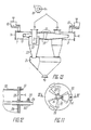
- the plant for the heat treatment of a polydisperse material contains four cylindrical drying chambers I, 2, 3, 4 (FIG. I), of which two drying chambers I and 2, 3 and 4 are coupled together along the generatrix of the cylindrical side walls 5 to form combs 6 are.
- An embodiment of the plant is possible which contains two cylindrical drying chambers coupled to one another.
- the two pairs of drying chambers I and 2, 3 and 4 are located on opposite sides and are arranged symmetrically relative to pipes 7, 8 for the supply of a heat transfer medium and the polydisperse material, which are tangential to the side wall 5 of each of the coupled drying chambers I, 2 , 3, 5 are attached perpendicular to the coupling plane of the drying chambers I and 2, 3 and 4 guided through the combs 6.
- the inlet openings 9 of the pipes 7, 8 for supplying the heat transfer medium and the polydisperse material are provided with a feed device for supplying the connected polydisperse wet goods.
- Air, water vapor, inert gases are used as the heat transfer medium depending on the technological purpose of the system.
- the pipes 7. 8 for the supply of the heat transfer medium and the polydisperse material are rectangular in cross section.
- the outlet openings II of the pipes 7, 8 for the supply of the heat transfer medium and the polydisperse are symmetrical relative to the coupling plane of the drying chambers I and 2, 3 and 4 guided by the combs 6.
- the outlet openings II of the pipes 7, 8 are at a distance from one another arranged, which is 0.5 to 1.5 of the equivalent diameter of the pipes 7, 8 for the supply of the heat transfer medium and the polydisperse material.
- openings I3, I4 are provided for overflowing the polydisperse material, each of which is provided with a pivotable slide I5 .
- a screw-shaped outlet connection I7 is attached to discharge the used heat transfer medium, which is connected to the suction connection of a blower I8.
- a cyclone separator 20 for separating the dried polydisperse material is coaxially fastened to the lower end wall 19 in each of the drying chambers 1, 2, 3, 4.
- a projection 2I is formed which is located in the space of each of the drying chambers I, 2, 3, 4.
- a blow-out pipe 22 arranged in the upper part of each cyclone separator 20 is arranged along the axis 23 of the drying chambers I, 2, 3. 4 and ver with the outlet connection I7 to discharge the used heat transfer medium bound.
- the .. dried polydisperse material from the cyclone separators 20 enters a bunker 24 and is then discharged by means of a screw 25 for loading.
- each of the pipes 7, 8 (FIG. 3) for the supply of the heat transfer medium and the polydisperse material with its outlet end is tangential to two projections 21 of the cyclone separators 20 of the drying chambers I, 3 and 2 , 4 attached.
- the edge 26 (FIG. 4) of the side wall 5 of each of the drying chambers I, 2, 3, 4 adjoining the wall I2 of the pipes 7, 8 is connected to the outer edge of the associated opening 13, I4 for overflow of the polydisperse material.
- slot nozzles 27 are provided with a pivotable slide 28.
- triangular flow hoods 29 surrounding the projections 21 of the cyclone separators 20 are provided over the entire height of each of the drying chambers I, 2, 3, 4.
- the triangular flow hoods 29 are designed in the form of a cranked plate.
- the projections 21 of the cyclone separator 20 are designed with a variable height, which is continuous in the direction from the triangular flow hoods 29 to the slot nozzle 27 decreases.
- the inlet ends 9 (FIG. 3) of each of the pipes 7, 8 for supplying the heat transfer medium and the polydisperse material are connected to additional pipes 30, 3I, which are connected by branch pipes 32, 33 to a Y-shaped pipe Forming an annular bend 34 are coupled together.
- the vertical transmission path 35 of the Y-shaped pipeline is located in the coupling plane of the cylindrical drying chambers I and 2, 3 and 4 guided by the comb 6.
- the vertical transmission path 35 is connected with the aid of a flange 36 to a disintegrator 37 for the polydisperse material.
- the disintegrator 37 for the polydisperse material contains a rotor 38 which is set in rotation by an electric motor 39. Blades 41 are attached to the axis 40 of the rotor 38.
- the disintegrator 37 (FIG. 5) for the polydisperse material is connected to a feed device 42 for feeding the polydisperse wet material.
- the feed device 42 (FIG. 3) for supplying the polydisperse wet material contains a loosening belt, which is designed as metal plates 43, 44 arranged on a shaft 45, and a screw 46, with the aid of which the polydisperse material is fed further into the disintegrator 37.
- the disintegrator 37 (FIG. 5) is also connected to a heating device 47, in which the heat transfer medium is heated with the steam supplied through a nozzle 48 (FIG. 3).
- each cyclone separator 20 for separating the dried polydisperse material in its lower part along the axis 49 of the cyclone separator 20 along an additional cylindrical connector 50 is provided, which is equipped with a device for twisting the heat transfer medium.
- the device for swirling the heat carrier is arranged in the form of a tangent Socket 5I (Fig. 6) formed.
- the tangentially arranged connecting pieces 5I of the cyclone separators 20 arranged in coupled drying chambers I and 2, 3 and 4 are connected in pairs to the branch pipes 32, 33 (FIG. 7) of the
- bunkers 53 In the lower part of the cyclone separator 20 (FIG. 3) there are bunkers 53 in which the dried polydisperse material collects and is discharged by means of the screws 54 through a pipeline 55 for loading.
- a coolant can be supplied in the lower part of each cyclone separator 20; in this case the additional cylindrical connector 50 (FIG. 8) is connected to the atmosphere or to a coolant source (not shown in the drawing).
- the device for swirling the heat transfer medium can be designed in the form of a tangentially arranged socket 5I (FIGS. 8, 6) and as a blade box 56 (FIG. 9, IO) which is attached to the upper end of the additional cylindrical socket 50.
- each cyclone separator 20 is provided with a regulator of the coolant consumption.
- the regulator of the coolant consumption is designed in the form of a pivotable slide 57 (FIGS. 8, 6). which is accommodated in the tangentially arranged nozzle 5I.
- the regulator for regulating the coolant consumption can be designed in the form of two sector diaphragms 58 (FIGS. II, I2), which are attached to a socket 60 on the lower end wall of the additional cylindrical connection piece 50 with the possibility of a fixed rotation by means of a screw 59.
- One of the sector diaphragms 58 on the lower end wall of the additional cylindrical connector 50 is rigid attached, while the other sector aperture 58 is arranged with the possibility of a fixed rotation and is fixed by means of a screw 6I.
- a device 62 is arranged along its axis 49 for separating the flows of the coolant and the used heat carrier, which is in the form of a rotation of a cycloid around its own tip line 63 formed rotating body is formed.
- the device 62 for separating the flows of the coolant and the used heat carrier is attached to a piston rod 64 with the possibility of a fixed movement along the axis 49 of the cyclone separator 20.
- the piston rod 64 is located in a guide bush 65 which is fastened by means of a screw 66.
- a third embodiment variant of the plant for the heat treatment of a polydisperse material is possible, which ensures a uniform distribution of the polydisperse material over the width of the drying chambers I, 2, 3, 4 (FIG. I3); at least one of the end walls 16, I9 is designed with an inclination in the direction of the arrangement of the openings I3, I4 for overflowing the polydisperse material.
- each of the drying chambers I, 2, 3, 4 (FIGS. 14, 15) additionally contains helical plates 67, which in the space between the side wall 5 of the drying chamber I, 2, 3, 4 and the side wall 68 of the projection 2I of the cyclone separator 20 located in the space of the drying chambers I, 2, 3, 4.
- the helical plates 67 are designed with a winding step which is the same as the height of the pipes 7, 8 for the supply of the heat transfer medium and the polydisperse material.
- the helical plates 67 (FIG. 16), which are arranged in the coupled drying chambers 1 and 2, 3 and 4, have opposite winding directions. Dabe-i has the Projection 21 of the cyclone separator 20 for separating the dried polydisperse material a height exceeding the height of the helical plate 67 which has been set up.
- the helical plates 67 (FIG. I4) are attached at one end to the upper wall 69 and at the other end to the lower wall 70 of the pipes 7, 8 for the supply of the heat transfer medium and the polydisperse material.
- the helical plates 67 are arranged above the pipes 7, 8 for the supply of the heat transfer medium and the polydisperse material.
- a fifth variant of the system is possible if in each drying chamber I, 2, 3, 4 (FIG. I7) the projection 21 of the cyclone separator 20 has a height that is essentially the same as the height of the drying chamber I, 2, 3, 4.
- a slot nozzle 7I is provided for the outflow of the used heat transfer medium and the dried pol y disperse material into the cyclone separator 20.
- the pipes 7, 8 for supplying the heat transfer medium and the polydisperse material are fastened in the upper part of the projection 2I of the cyclone separator 20.
- the helical plates 67 are located below the pipes 7, 8.
- the helical plates 67 are attached at one end to the edge of the slot nozzle 71.
- the plant for the heat treatment of a pol y disperse material is operated as follows.
- the preheated heat transfer medium and the polydisperse wet material are introduced from the feed device 10 (FIGS. 1, 2) into the pipelines 7. 8.
- the existing streams of the floating mixture of gas and polydisperse are accelerated in the pipelines 7 and 8 and fed into the drying chambers I and 2, 3 and 4 as opposing streams directed at an angle of 180 ° to each other; they collide in the coupling plane of the drying chambers 1 and 2, 3 and 4 guided by the comb 6.
- the polydisperse material arrives from the drying chambers I and 2, 3 and 4, in which the area of the centrifugal high pressure prevails through the openings I3, 14 to overflow the polydisperse material into the pipes 7, 8, ie into the area of the static overpressure.
- the rotating polydisperse material penetrates under the action of the inertial forces into straight streams of the floating starting mixture of gas and polydisperse material, is accelerated again and then in the subsequent assembly collide with the opposing flows of the floating mixture of gas and polydisperse material.
- the kinetic energy of the streams of the floating gas mixture in the drying chambers I, 2, 3, 4 is used in the cyclone separators 20. From the cyclone separators. 20 the dried polydisperse material gets into the bunker 24 and is then forwarded to the loading by means of the screw 25. The used heat transfer medium is sucked off through the blow-out pipe 22 and the screw-shaped outlet connection 17 by means of the blower 18 into the atmosphere or for sanitary cleaning.
- the setting of the system for optimal aerodynamic operation that is, the regulation of the residence time of the polydisperse material in the zone of the heat treatment is carried out by regulating the return of the polydisperse material from the drying chambers I, 2, 3, 4 in pipes 7, 8 for the Feeding of the heat transfer medium and the polydisperse material by means of the pivotable slide 15.
- the pivotable slide I5 of the openings I3, 14 is opened further to overflow the polydisperse material, the number of circulations increases. cycles of the floating mixture of gas and polydisperse, the concentration of the polydisperse in the zone of highly active aerodynamic conditions increases and the heat and mass transfer process is intensified. However, this increases the aerodynamic resistance of the system.
- the system is used in the second embodiment variant.
- the heat transfer medium heated in the heating apparatus 47 (FIG. 3) and the polydisperse wet material are fed from the feed device 42 by means of the screw 46 into the disintegrator 37 for the polydisperse material.
- the screw-type feed device 42 is operated with the polydisperse wet material, lumps inevitably arise from the polydisperse material.
- the disintegrator 37 (FIG. 4) the polydisperse material interacts with the rotating blades 4I of the rotor 38, is loosened and discharged with the heat transfer medium into the vertical transmission path 35 (FIG. 3) of the Y-shaped pipeline.
- the fine fraction of the polydisperse material moves in the direction of the axis of rotation of the floating gas mixture out over the annular bend 34 and passes through the tangentially arranged nozzle 5I via the cylindrical nozzle 50 into the cyclone separator 20 for drying.
- the amount of the floating, finely dispersed gas mixture and the limit grain size of the particles of the polydisperse material are regulated by the pivotable slide 52.
- the floating mixture of gas and the coarsely disperse fraction of the polydisperse material is fed into the pipes 7, 8.
- the gas mixture flows in streams 29, formed by the flow hoods, in strictly tangential directions into the drying chambers I, 2, 3, 4, in which it is rotated in opposite directions.
- the heat treatment is carried out similarly to that described above.
- the flow of the floating mixture of gas and polydisperse material rotates in the spaces of the drying chambers I, 2, 3, 4 formed by the side walls of the projections 21 of the cyclone separators 20 and the side walls 5 of the drying chambers I, 2, 3, 4, after which the Particles of the polydiapered material with a higher inertia, ie the larger and less dried particles, are returned to the pipelines 7, 8 through the openings 13, I4 for overflowing the polydisperse material for subsequent collision in countercurrents in the floating mixture of gas and polydisperse material, while the dried particles of the polydisperse material are discharged through the slot nozzle 27 in tangentially directed streams into the cyclone separator 20, where the polydisperse material and the used heat transfer medium are separated from one another, swirl
- the devices for the heat transfer medium and the polydisperse material designed in the form of a tangentially arranged connection piece 5I (FIGS. 8, 6) or one Paddle box 56 (FIGS. 9, 10) ensure the introduction of the swirled flow of the floating mixture of gas and polydisperse material into the conical part of the cyclone separator 20 (FIG. 9) through the additional cylindrical connection piece 50.
- the dried polydisperse material separated from the heat transfer medium is discharged in descending screw flow into the lower part of the cyclone separator 20, into the cooling zone 72 of the polydisperse material, which is located below the device 62 for separating the flows of the coolant and the used heat transfer medium from one another.
- the coolant is supplied through the cylindrical connector 50 and is set into a rotary movement as it flows through the tangential connector 5I.
- the spiral flow of the polydisperse material flowing under the action of the inertial force from the separation zone 73 above the device 62 actively interacts with the rotating, oppositely directed flow of the cooling air.
- the cooled, polydisperse material then reaches the bunker 24.
- the consumed coolant passes from the cooling zone 72 into the upper part of the cyclone separator 20, that is to say into the separation zone 73 of the polydisperse material, where it is used up Heat carrier mixed and discharged in a common spiral stream through the blow pipe 22 (Fig. 3).
- the common gas stream is then fed for sanitary cleaning, which is usually carried out using the wet process.
- the setting of the system to optimum technological conditions for the cooling of the polydisperse material is by a change of two characteristic values of the length uz 1 0 the cooling zone 72 (Fig. 9) of the poly-dispersed material and the flow rate of the coolant taken before-0.
- the length l o of the cooling zone 72 of the plydisperse Good is changed by changing the axial position of the device 62. With a displacement of the device 62 toward the exhaust pipe 22 of the cyclone separator 20 through the length of the cooling zone 72 is enlarged the polydisperse good, whereby the process of cooling expires intensive, while the separation capacity of the cyclone separators 20 1 0 of the deposition in a reduction in the length 73 of the polydisperse material sinks.
- the change in the coolant consumption quantity is achieved with the aid of the pivotable slide 57 (FIG. 6) if the regulator of the coolant consumption is designed in the form of a tangentially arranged connection piece 51, and by changing the pivoting angle of the sector shutters 58 (FIG. I), if the controller is designed as two sector diaphragms 58.
- the change in the amount of coolant consumed leads to a change in the balance between the cooling process and the hydrodynamics of the rotating stream of the polydisperse to be cooled. Since the dynamic influence of the coolant on the polydisperse material is insignificant when the coolant consumption amounts are low, there is practically no change in the strand-like structure of the flow of the polydisperse material, as a result of which the cooling intensity of the polydisperse material is also low. If the amount of coolant consumed is increased, the speed of rotation and the dynamic effect of the coolant on the polydisperse material to be cooled increase. The speed of the flow of the polydisperse material decreases and in the cooling zone 72 (FIG. 9) of the polydisperse material a stable annular layer is created which interacts effectively with the coolant. Such operating conditions ensure a maximum
- Holding capacity of the cooling zone 72 of the polydisperse material (amount of the simultaneously in zone 72 lingering polydisperse good).
- each drying chamber I, 2. 3, 4 (FIG. 2) is expediently inclined in the direction the arrangement of the openings 13, I4 out because the probability of large particles of the polydisperse material falling out of the rotating Current of the floating gas mixture in the area of the openings 13, I4 is quite low.
- the upper and lower end walls 16, I9 (FIG. I3) of each drying chamber are expediently made with a symmetrical inclination in the direction of the Arrangement of the openings 13, 14 attached in order to exclude a failure of large particles of the polydisperse material from the rotating stream of the floating gas mixture. In this case, even the particularly large particles of the polydisperse material are passed into the channels 7, 8 for a new circulation.
- the fourth version of the system in which a high-temperature heat transfer medium with a temperature of 300 ° to 800 ° C is used .
- the oppositely directed streams of the floating mixture of gas and polydisperse material supplied via the pipes 7, 8 (FIGS. 14, 17) bump into each other several times in the arrangement level of the combs 6 of the drying chambers I and 2, 3 and 4 in the zones 74 each winding of the helical plates 67 together.
- the floating mixture of gas and polydisperse material rotates over the spiral channels without retrograde mixing, i.e. there is no recirculation of both the heat transfer medium and the particles of the polydisperse material.
- the thermal energy of the heat transfer medium can be used to the maximum and the energy expenditure reduced.
- the spent heat transfer medium and the dried polydisperse material are then passed through the upper end face of the projection 2I (FIG. 14) or through the slot nozzle 71 (FIG. 17) on the side wall 68 of the projection 2I fed into the cyclone separator 20.
- the material is fed from the upper level heights of the drying chambers 1, 2, 3, 4, i.e. the helical plates are arranged below the pipes 7, 8.
- the kinetic energy of tangentially directed currents is used, which after the collision in zone 74 in the coupling plane of the drying chambers I and 2. 3 and 4 are formed, whereby the flow resistance of the system can be reduced.
- the flow resistance of the plant can be reduced by 1.2 to 1.4 times.
- a high-temperature heat transfer medium can be used for the heat treatment of a coarsely disperse material; the process of heat treatment is carried out when the used heat carrier is practically completely saturated with wet steam. As a result, the energy expenditure can be reduced by 30 to 40%.
- the present invention can be used in food. Chemical, pharmaceutical. Pulp and paper industry, in the production of building materials, in branches of the agricultural industry complex for drying milk sugar, starch, vinyl chloride copolymers, medical preparations, the shredded paper pulp, sawdust, peat, sand, hair and plumage of the slaughtered animals crushed grass mass as well as for roasting magnesite, dolomite, for cooling polydisperse bulk materials.
Landscapes
- Engineering & Computer Science (AREA)
- Mechanical Engineering (AREA)
- General Engineering & Computer Science (AREA)
- Drying Of Solid Materials (AREA)
- Junction Field-Effect Transistors (AREA)
- Processing And Handling Of Plastics And Other Materials For Molding In General (AREA)
Abstract
Applications Claiming Priority (1)
| Application Number | Priority Date | Filing Date | Title |
|---|---|---|---|
| PCT/SU1989/000011 WO1990008296A1 (fr) | 1989-01-18 | 1989-01-18 | Installation de traitement thermique de matieres polydispersees |
Publications (2)
| Publication Number | Publication Date |
|---|---|
| EP0406421A1 true EP0406421A1 (fr) | 1991-01-09 |
| EP0406421A4 EP0406421A4 (en) | 1991-07-03 |
Family
ID=21617385
Family Applications (1)
| Application Number | Title | Priority Date | Filing Date |
|---|---|---|---|
| EP19890904299 Withdrawn EP0406421A4 (en) | 1989-01-18 | 1989-01-18 | Installation for heat treatment of polydispersed materials |
Country Status (4)
| Country | Link |
|---|---|
| EP (1) | EP0406421A4 (fr) |
| JP (1) | JPH03504155A (fr) |
| DK (1) | DK222890A (fr) |
| WO (1) | WO1990008296A1 (fr) |
Cited By (1)
| Publication number | Priority date | Publication date | Assignee | Title |
|---|---|---|---|---|
| EP3798559A1 (fr) * | 2019-10-15 | 2021-03-31 | Plasmaq - Maquinas e Equipamentos Para a Industria de Plasticos, Lda | Équipement de désorroutage et de séchage des déchets de films plastiques à recycler |
Families Citing this family (2)
| Publication number | Priority date | Publication date | Assignee | Title |
|---|---|---|---|---|
| DE4421714A1 (de) | 1994-06-21 | 1996-01-04 | Bosch Gmbh Robert | Kraftstoffeinspritzsystem |
| GB0407440D0 (en) | 2004-04-01 | 2004-05-05 | Eja Ltd | Safety switch assembly |
Citations (5)
| Publication number | Priority date | Publication date | Assignee | Title |
|---|---|---|---|---|
| US2494153A (en) * | 1945-02-23 | 1950-01-10 | Micronizer Company | Drying and pulverizing method and apparatus |
| US2520747A (en) * | 1945-08-22 | 1950-08-29 | Broek Wouter Van Den | Fluid current drier for grass and the like |
| US3329418A (en) * | 1965-03-30 | 1967-07-04 | Fluid Energy Proc & Equipment | Apparatus for treating wet solid and semi-solid materials in a fluid stream |
| US3339286A (en) * | 1965-03-11 | 1967-09-05 | Fluid Energy Proc And Equipmen | Method and apparatus for drying wet pulverulent material in a gaseous path |
| SU983412A2 (ru) * | 1981-06-19 | 1982-12-23 | Могилевский технологический институт | Установка дл сушки растворов и суспензий |
Family Cites Families (3)
| Publication number | Priority date | Publication date | Assignee | Title |
|---|---|---|---|---|
| SU870874A1 (ru) * | 1980-01-23 | 1981-10-07 | Могилевский технологический институт | Установка дл сушки растворов и суспензий |
| SU1044920A1 (ru) * | 1982-06-11 | 1983-09-30 | Могилевский технологический институт | Установка дл сушки суспензий |
| FR2543280B1 (fr) * | 1983-03-23 | 1987-12-04 | Gaz De France | Procede et installation de traitement par voie thermique de produits divises |
-
1989
- 1989-01-18 JP JP50384989A patent/JPH03504155A/ja active Pending
- 1989-01-18 WO PCT/SU1989/000011 patent/WO1990008296A1/fr not_active Application Discontinuation
- 1989-01-18 EP EP19890904299 patent/EP0406421A4/de not_active Withdrawn
-
1990
- 1990-09-17 DK DK222890A patent/DK222890A/da not_active Application Discontinuation
Patent Citations (5)
| Publication number | Priority date | Publication date | Assignee | Title |
|---|---|---|---|---|
| US2494153A (en) * | 1945-02-23 | 1950-01-10 | Micronizer Company | Drying and pulverizing method and apparatus |
| US2520747A (en) * | 1945-08-22 | 1950-08-29 | Broek Wouter Van Den | Fluid current drier for grass and the like |
| US3339286A (en) * | 1965-03-11 | 1967-09-05 | Fluid Energy Proc And Equipmen | Method and apparatus for drying wet pulverulent material in a gaseous path |
| US3329418A (en) * | 1965-03-30 | 1967-07-04 | Fluid Energy Proc & Equipment | Apparatus for treating wet solid and semi-solid materials in a fluid stream |
| SU983412A2 (ru) * | 1981-06-19 | 1982-12-23 | Могилевский технологический институт | Установка дл сушки растворов и суспензий |
Non-Patent Citations (3)
| Title |
|---|
| Drying Technology vol. 7, no. 2, Juni 1989, New York, US Seiten 219-266; Kudra et al: "IMPINGEMENT STREAM DRYERS FOR PARTICLES AND PASTES" * |
| See also references of WO9008296A1 * |
| SOVIET INVENTIONS ILLUSTRATED, Section P/Q, Week K43, 7 Dec. 83, DERWENT PUBLICATIONS LTD., LONDON GB, class Q, no. 83-799779/43 & SU-A-983412 (MOGIL TECHN INST) 23 Dec. 82 * |
Cited By (1)
| Publication number | Priority date | Publication date | Assignee | Title |
|---|---|---|---|---|
| EP3798559A1 (fr) * | 2019-10-15 | 2021-03-31 | Plasmaq - Maquinas e Equipamentos Para a Industria de Plasticos, Lda | Équipement de désorroutage et de séchage des déchets de films plastiques à recycler |
Also Published As
| Publication number | Publication date |
|---|---|
| EP0406421A4 (en) | 1991-07-03 |
| DK222890A (da) | 1990-11-16 |
| JPH03504155A (ja) | 1991-09-12 |
| WO1990008296A1 (fr) | 1990-07-26 |
| DK222890D0 (da) | 1990-09-17 |
Similar Documents
| Publication | Publication Date | Title |
|---|---|---|
| EP1956326B1 (fr) | Dispositif de suppression de fluides et/ou de substances solides | |
| DE69720114T2 (de) | Zweistufiger Sprühtrockner | |
| EP0371971B1 (fr) | Chambre a lit bouillonnant | |
| EP3486591B1 (fr) | Dispositif de séchage par vaporisation du lit fluidisé | |
| DD249412A5 (de) | Verfahren und vorrichtung zum trocken eines fluessigen materials | |
| DE69633192T2 (de) | Verfahren und vorrichtung zur trocknung von pulverisierten material | |
| DE3314887A1 (de) | Gasverteilboden fuer trockner od.dgl. mit kreisendem fliessbett | |
| EP2326900B1 (fr) | Procédé et dispositif de séchage de biomasse | |
| DE2129186A1 (de) | Verfahren und Vorrichtung zur Fluidisation von partikelförmigen Materialien | |
| DE2335514A1 (de) | Vorrichtung mit einer an eine druckoder saugquelle fuer heisses gas anschliessbaren wirbelschichtkammer | |
| EP0597092B1 (fr) | Appareil d'obtention d'un produit granule | |
| DE2634072B2 (de) | Trommeltrockner | |
| DE2155240B2 (de) | Vorrichtung zur kontinuierlichen Behandlung, z.B. durch Trocknung oder Kühlung von staub-, pulver- und granulatförmigem Material | |
| EP0406421A1 (fr) | Installation de traitement thermique de matieres polydispersees | |
| DD217004A1 (de) | Vorrichtung zur strahlschichttrocknung klebrig-koerniger und thermolabiler stoffe | |
| DE897977C (de) | Vorrichtung zur Trocknung von Gut mittels heisser Gase | |
| DE2555553A1 (de) | Verfahren zum trocknen nasser partikel und zentrifugentrocknungsanlage | |
| DE2950749C2 (fr) | ||
| EP0197171A1 (fr) | Séchoir à basse température pour une matière fibreuse pressurée | |
| DE19538048C2 (de) | Vorrichtung zum Trocknen und Erwärmen von einem Koksofen zuzuführender Kohle | |
| DE3642276C2 (fr) | ||
| DE2634513C3 (de) | Vorrichtung zum Trocknen disperser Stoffe in einer zylinderförmigen Kammer | |
| DE2243670A1 (de) | Verfahren und einrichtung zum kontinuierlichen trocknen von koernigen stoffen in einer wirbelschicht | |
| DE19757624A1 (de) | Verfahren zur Kühlung von Granulat | |
| AT263526B (de) | Vorrichtung zur Behandlung von aus Pflanzenprodukten stammenden Pasten mittels Bleichungsreagentien |
Legal Events
| Date | Code | Title | Description |
|---|---|---|---|
| PUAI | Public reference made under article 153(3) epc to a published international application that has entered the european phase |
Free format text: ORIGINAL CODE: 0009012 |
|
| 17P | Request for examination filed |
Effective date: 19900919 |
|
| AK | Designated contracting states |
Kind code of ref document: A1 Designated state(s): CH DE FR GB LI NL SE |
|
| A4 | Supplementary search report drawn up and despatched |
Effective date: 19910516 |
|
| AK | Designated contracting states |
Kind code of ref document: A4 Designated state(s): CH DE FR GB LI NL SE |
|
| STAA | Information on the status of an ep patent application or granted ep patent |
Free format text: STATUS: THE APPLICATION HAS BEEN WITHDRAWN |
|
| 18W | Application withdrawn |
Withdrawal date: 19910819 |
|
| R18W | Application withdrawn (corrected) |
Effective date: 19910819 |