EP0406421A1 - Installation for heat treatment of polydispersed materials - Google Patents
Installation for heat treatment of polydispersed materials Download PDFInfo
- Publication number
- EP0406421A1 EP0406421A1 EP89904299A EP89904299A EP0406421A1 EP 0406421 A1 EP0406421 A1 EP 0406421A1 EP 89904299 A EP89904299 A EP 89904299A EP 89904299 A EP89904299 A EP 89904299A EP 0406421 A1 EP0406421 A1 EP 0406421A1
- Authority
- EP
- European Patent Office
- Prior art keywords
- polydisperse
- polydisperse material
- heat transfer
- transfer medium
- cyclone separator
- Prior art date
- Legal status (The legal status is an assumption and is not a legal conclusion. Google has not performed a legal analysis and makes no representation as to the accuracy of the status listed.)
- Withdrawn
Links
Images


Classifications
-
- F—MECHANICAL ENGINEERING; LIGHTING; HEATING; WEAPONS; BLASTING
- F26—DRYING
- F26B—DRYING SOLID MATERIALS OR OBJECTS BY REMOVING LIQUID THEREFROM
- F26B17/00—Machines or apparatus for drying materials in loose, plastic, or fluidised form, e.g. granules, staple fibres, with progressive movement
- F26B17/10—Machines or apparatus for drying materials in loose, plastic, or fluidised form, e.g. granules, staple fibres, with progressive movement with movement performed by fluid currents, e.g. issuing from a nozzle, e.g. pneumatic, flash, vortex or entrainment dryers
- F26B17/108—Machines or apparatus for drying materials in loose, plastic, or fluidised form, e.g. granules, staple fibres, with progressive movement with movement performed by fluid currents, e.g. issuing from a nozzle, e.g. pneumatic, flash, vortex or entrainment dryers using impinging streams of entrained material
Definitions
- the present invention relates to the heat treatment of substances and relates in particular to plants for the heat treatment of a polydisperse material.
- a plant for drying a polydisperse material is widely known (Express-informatsia. Zarubezhny opyt ", Tsintikhimneftemash, Series XM-I, No. 6, 1985, Tamir A., Elperin I., Lussatto K.”
- Convection dryer with counter-rotating beams ", S. 5 to 9) which contains a cylindrical drying chamber of the cyclone type, channels for supplying a heat transfer medium and the polydisperse material, which are connected to a feed device for polydisperse wet material and are attached tangentially to the side wall of the drying chamber.
- the system also contains a static swirler, which is in the form of helical plates which are formed between the side wall of the drying chamber and the side wall of one in the space of the drying chamber underfolded blow-out pipe are consolidated.
- the flows of the floating mixture of gas and polydisperse are fed tangentially to the collision zone on the cylindrical surface of the drying chamber, in which a centrifugal force field acts on the flows of the polydisperse.
- the particles of the polydisperse material move mainly on the side wall of the drying chamber. As a result, the contact of the particles of the polydisperse material with the heat transfer medium becomes worse. Disassemble the particles of the polydisperse material in layers according to the grain size, the layer of larger particles of the polydisperse is shielded from the layer of smaller particles.
- the residence time of the particles of the polydisperse material in the collision zone (a few hundredths of a second) and the residence time of the particles of the polydisperse material in the space between the turns of the helical plates are very short, as a result of which the heat treatment of the polydisperse material is not very effective. As a result, this system cannot be used to dry the polydisperse material with a high moisture content and a high diffusion resistance.
- the system under consideration is characterized by a high flow resistance because to separate the dried polydisperse material from the used heat transfer medium, the flows of the floating mixture of gas and polydisperse material are swirled by means of the helical plates, the current often changing its direction of movement according to random trajectories. This leads to large energy losses in energy dissipation.
- a system for the heat treatment of a polydisperse material for example solutions and suspensions, is also known (SU, A, 9834I2).
- the two cylindrical Tro k - contains kenwaitn which perpendicularly arranged and the generatrices of the side walls to each other ge are coupled.
- Pipelines for feeding the heat transfer medium and the polydisperse material are attached tangentially to the drying chambers.
- the adjacent surfaces of the drying chambers, which connect to the tangential pipes, form a common flat wall.
- the floating mixture of gas and polydisperse wet material is accelerated in the tangential pipelines and fed into the drying chambers as opposing flows directed at an angle of 180 ° to each other.
- a decaying oscillation of the particles of the polydisperse material arises and after the velocity of the particles of the polydisperse material has decreased to the floating speed, they are discharged from the collision zone.
- the intensity of the heat and material exchange in the stream of the polydisperse material is very high, while the residence time of the particles of the polydisperse material in the collision zone is very short (a few fractions of a second), which leads to a low effectiveness of the process of heat treatment of polydisperse leads.
- the gas mixture is fed into the peripheral region of the drying chamber in tangentially directed flows and impacts the cylindrical wall of the drying chamber, which leads to dissipative losses of the kinetic energy.
- the present invention has for its object to provide a system for the heat treatment of a polydisperse material, in which the intensity of the heat and material exchange in the flow of the floating mixture of gas and polydisperse material can be increased and the energy expenditure reduced by the device-technical design.
- the system additionally contains two coupled drying chambers, which are arranged on the opposite side relative to the pipes for supplying the heat transfer medium and the polydisperse material symmetrically to the coupled main drying chambers.
- openings for overflowing the polydisperse material are provided on the walls of each of the pipes for supplying the heat transfer medium and the polydisperse material, which adjoin the side walls of the drying chambers.
- the openings for overflowing the polydisperse material in each of the pipes for supplying the heat transfer medium and the polydisperse material are provided with pivotable slides.
- the pipelines for supplying the heat transfer medium and the polydisperse material are attached with their outlet ends to the projections of the cyclone separators located in the rooms of the assigned drying chambers for separating the dried polydisperse material.
- the treatment of poly-dispersed material with a high moisture content di p system includes a disintegrator for the polydisperse Good and pipelines in addition, connected with the inlet openings of the pipes for supplying the heat carrier and the poly-dispersed material, and by branch pipes of a Y - Shaped pipe are coupled to each other, the vertical transmission path of the Y-shaped pipe is in the coupling plane of the drying chambers and is connected to the disintegrator for the polydisperse material, to which the feed device for the polydisperse material and a heating device are connected.
- the disintegrator for the polydisperse material is arranged below the perpendicular transmission path of the Y-shaped pipeline so that the axis of its runner comes to lie perpendicular to the coupling plane of the drying chambers.
- the system additionally contains flow hoods, which are attached at the outlet end of each pipeline for supplying the heat transfer medium and the polydisperse material over the entire height of the drying chamber and in the form of a cranked one Plate are formed.
- a slot nozzle is provided, which is provided with a pivotable slide.
- each cyclone separator for separating the dried polydisperse material is provided with an additional cylindrical connection piece which is arranged in the lower part and coaxially with the cyclone separator and is provided with a device for rotating the heat transfer medium.
- the device for rotating the heat transfer medium is designed in the form of a tangentially arranged nozzle, which is attached in the lower part of the additionally provided, cylindrical nozzle .
- each cyclone separator for separating the dried polydisperse good -shaped with branch pipes of the Y pipeline at the coupling point in pairs connected to additional lines, at which point a pivotable slide is arranged equidistant.
- the additional cylindrical connection piece is connected to a coolant source, the additional cylindrical connection piece being provided with a regulator of the coolant consumption, while in the lower part each Cyclone separator for separating the dried polydisperse material a device for separating the flows of the coolant and the consumption th heat transfer medium is housed.
- the regulator for regulating the coolant consumption is designed in the form of sector diaphragms, which can be arranged on the lower end wall of the additional cylindrical connector with the possibility of a fixed rotation are attached.
- the means for separating the streams of the coolant and the spent heat carrier in the form of a by rotating a Z y k colloids around their Center line formed formed body and is attached to a piston rod with the possibility of a fixed movement along the axis of the cyclone separator for separating the dried polydisperse material.
- Ra is expedient that, in order to ensure reliable circulation of the flow of the polydisperse material from the drying chambers into the pipelines for supplying the heat transfer medium and the polydisperse material, at least one of the end walls in each drying chamber with an inclination in the direction of the arrangement of the opening for overflowing the polydisperse Good is done.
- a high-temperature heat transfer medium are provided for treatment of various polydisperse materials in the plant additionally helical plates for use, of the side wall of the drying chamber and the side wall of the Vorsprun- there g of the cyclone separator for separating the dried polydisperse good space formed each Drying chamber are arranged so that the helical, in the coupled drying chambers have the opposite winding direction, the protrusion of the cyclone separator has a height that exceeds the height of the helical plate.
- the pipes for the supply of the heat transfer medium and the polydisperse material are fastened in the lower part of the projection of the cyclone separator for separating the dried polydisperse material in each drying chamber.
- the helical plates are located above these pipes.
- the projection of the cyclone separator for separating the dried polydisperse material with a height which is essentially the same as the height of the drying chamber, on the side wall of the projection of the cyclone separator in its lower part Part to provide a slot nozzle and to fix the pipes for supplying the heat transfer medium and the polydisperse material in the upper part of the projection of the cyclone separator, the helical plates are arranged below these pipes and attached to the edge of the slot nozzle.
- the use of the present invention makes it possible to increase the intensity of the heat and mass exchange in the flow of the floating mixture of gas and polydisperse material and the residence time of the polydisperse material in the zone of highly active aerodynamic conditions, namely in the collision zone of the opposing rectilinear streams of the levitant Extend mixture of gas and polydisperse material.
- An extension of the residence time of the polydisperse material in the zone of highly active aerodynamic conditions as well as the unification of technological processes of heat handling of the polydisperse material and the deposition of the dried polydisperse material in a work space lead to a reduction in the aerodynamic resistance, as a result of which the energy expenditure for the operation of the system is reduced.
- the plant for the heat treatment of a polydisperse material contains four cylindrical drying chambers I, 2, 3, 4 (FIG. I), of which two drying chambers I and 2, 3 and 4 are coupled together along the generatrix of the cylindrical side walls 5 to form combs 6 are.
- An embodiment of the plant is possible which contains two cylindrical drying chambers coupled to one another.
- the two pairs of drying chambers I and 2, 3 and 4 are located on opposite sides and are arranged symmetrically relative to pipes 7, 8 for the supply of a heat transfer medium and the polydisperse material, which are tangential to the side wall 5 of each of the coupled drying chambers I, 2 , 3, 5 are attached perpendicular to the coupling plane of the drying chambers I and 2, 3 and 4 guided through the combs 6.
- the inlet openings 9 of the pipes 7, 8 for supplying the heat transfer medium and the polydisperse material are provided with a feed device for supplying the connected polydisperse wet goods.
- Air, water vapor, inert gases are used as the heat transfer medium depending on the technological purpose of the system.
- the pipes 7. 8 for the supply of the heat transfer medium and the polydisperse material are rectangular in cross section.
- the outlet openings II of the pipes 7, 8 for the supply of the heat transfer medium and the polydisperse are symmetrical relative to the coupling plane of the drying chambers I and 2, 3 and 4 guided by the combs 6.
- the outlet openings II of the pipes 7, 8 are at a distance from one another arranged, which is 0.5 to 1.5 of the equivalent diameter of the pipes 7, 8 for the supply of the heat transfer medium and the polydisperse material.
- openings I3, I4 are provided for overflowing the polydisperse material, each of which is provided with a pivotable slide I5 .
- a screw-shaped outlet connection I7 is attached to discharge the used heat transfer medium, which is connected to the suction connection of a blower I8.
- a cyclone separator 20 for separating the dried polydisperse material is coaxially fastened to the lower end wall 19 in each of the drying chambers 1, 2, 3, 4.
- a projection 2I is formed which is located in the space of each of the drying chambers I, 2, 3, 4.
- a blow-out pipe 22 arranged in the upper part of each cyclone separator 20 is arranged along the axis 23 of the drying chambers I, 2, 3. 4 and ver with the outlet connection I7 to discharge the used heat transfer medium bound.
- the .. dried polydisperse material from the cyclone separators 20 enters a bunker 24 and is then discharged by means of a screw 25 for loading.
- each of the pipes 7, 8 (FIG. 3) for the supply of the heat transfer medium and the polydisperse material with its outlet end is tangential to two projections 21 of the cyclone separators 20 of the drying chambers I, 3 and 2 , 4 attached.
- the edge 26 (FIG. 4) of the side wall 5 of each of the drying chambers I, 2, 3, 4 adjoining the wall I2 of the pipes 7, 8 is connected to the outer edge of the associated opening 13, I4 for overflow of the polydisperse material.
- slot nozzles 27 are provided with a pivotable slide 28.
- triangular flow hoods 29 surrounding the projections 21 of the cyclone separators 20 are provided over the entire height of each of the drying chambers I, 2, 3, 4.
- the triangular flow hoods 29 are designed in the form of a cranked plate.
- the projections 21 of the cyclone separator 20 are designed with a variable height, which is continuous in the direction from the triangular flow hoods 29 to the slot nozzle 27 decreases.
- the inlet ends 9 (FIG. 3) of each of the pipes 7, 8 for supplying the heat transfer medium and the polydisperse material are connected to additional pipes 30, 3I, which are connected by branch pipes 32, 33 to a Y-shaped pipe Forming an annular bend 34 are coupled together.
- the vertical transmission path 35 of the Y-shaped pipeline is located in the coupling plane of the cylindrical drying chambers I and 2, 3 and 4 guided by the comb 6.
- the vertical transmission path 35 is connected with the aid of a flange 36 to a disintegrator 37 for the polydisperse material.
- the disintegrator 37 for the polydisperse material contains a rotor 38 which is set in rotation by an electric motor 39. Blades 41 are attached to the axis 40 of the rotor 38.
- the disintegrator 37 (FIG. 5) for the polydisperse material is connected to a feed device 42 for feeding the polydisperse wet material.
- the feed device 42 (FIG. 3) for supplying the polydisperse wet material contains a loosening belt, which is designed as metal plates 43, 44 arranged on a shaft 45, and a screw 46, with the aid of which the polydisperse material is fed further into the disintegrator 37.
- the disintegrator 37 (FIG. 5) is also connected to a heating device 47, in which the heat transfer medium is heated with the steam supplied through a nozzle 48 (FIG. 3).
- each cyclone separator 20 for separating the dried polydisperse material in its lower part along the axis 49 of the cyclone separator 20 along an additional cylindrical connector 50 is provided, which is equipped with a device for twisting the heat transfer medium.
- the device for swirling the heat carrier is arranged in the form of a tangent Socket 5I (Fig. 6) formed.
- the tangentially arranged connecting pieces 5I of the cyclone separators 20 arranged in coupled drying chambers I and 2, 3 and 4 are connected in pairs to the branch pipes 32, 33 (FIG. 7) of the
- bunkers 53 In the lower part of the cyclone separator 20 (FIG. 3) there are bunkers 53 in which the dried polydisperse material collects and is discharged by means of the screws 54 through a pipeline 55 for loading.
- a coolant can be supplied in the lower part of each cyclone separator 20; in this case the additional cylindrical connector 50 (FIG. 8) is connected to the atmosphere or to a coolant source (not shown in the drawing).
- the device for swirling the heat transfer medium can be designed in the form of a tangentially arranged socket 5I (FIGS. 8, 6) and as a blade box 56 (FIG. 9, IO) which is attached to the upper end of the additional cylindrical socket 50.
- each cyclone separator 20 is provided with a regulator of the coolant consumption.
- the regulator of the coolant consumption is designed in the form of a pivotable slide 57 (FIGS. 8, 6). which is accommodated in the tangentially arranged nozzle 5I.
- the regulator for regulating the coolant consumption can be designed in the form of two sector diaphragms 58 (FIGS. II, I2), which are attached to a socket 60 on the lower end wall of the additional cylindrical connection piece 50 with the possibility of a fixed rotation by means of a screw 59.
- One of the sector diaphragms 58 on the lower end wall of the additional cylindrical connector 50 is rigid attached, while the other sector aperture 58 is arranged with the possibility of a fixed rotation and is fixed by means of a screw 6I.
- a device 62 is arranged along its axis 49 for separating the flows of the coolant and the used heat carrier, which is in the form of a rotation of a cycloid around its own tip line 63 formed rotating body is formed.
- the device 62 for separating the flows of the coolant and the used heat carrier is attached to a piston rod 64 with the possibility of a fixed movement along the axis 49 of the cyclone separator 20.
- the piston rod 64 is located in a guide bush 65 which is fastened by means of a screw 66.
- a third embodiment variant of the plant for the heat treatment of a polydisperse material is possible, which ensures a uniform distribution of the polydisperse material over the width of the drying chambers I, 2, 3, 4 (FIG. I3); at least one of the end walls 16, I9 is designed with an inclination in the direction of the arrangement of the openings I3, I4 for overflowing the polydisperse material.
- each of the drying chambers I, 2, 3, 4 (FIGS. 14, 15) additionally contains helical plates 67, which in the space between the side wall 5 of the drying chamber I, 2, 3, 4 and the side wall 68 of the projection 2I of the cyclone separator 20 located in the space of the drying chambers I, 2, 3, 4.
- the helical plates 67 are designed with a winding step which is the same as the height of the pipes 7, 8 for the supply of the heat transfer medium and the polydisperse material.
- the helical plates 67 (FIG. 16), which are arranged in the coupled drying chambers 1 and 2, 3 and 4, have opposite winding directions. Dabe-i has the Projection 21 of the cyclone separator 20 for separating the dried polydisperse material a height exceeding the height of the helical plate 67 which has been set up.
- the helical plates 67 (FIG. I4) are attached at one end to the upper wall 69 and at the other end to the lower wall 70 of the pipes 7, 8 for the supply of the heat transfer medium and the polydisperse material.
- the helical plates 67 are arranged above the pipes 7, 8 for the supply of the heat transfer medium and the polydisperse material.
- a fifth variant of the system is possible if in each drying chamber I, 2, 3, 4 (FIG. I7) the projection 21 of the cyclone separator 20 has a height that is essentially the same as the height of the drying chamber I, 2, 3, 4.
- a slot nozzle 7I is provided for the outflow of the used heat transfer medium and the dried pol y disperse material into the cyclone separator 20.
- the pipes 7, 8 for supplying the heat transfer medium and the polydisperse material are fastened in the upper part of the projection 2I of the cyclone separator 20.
- the helical plates 67 are located below the pipes 7, 8.
- the helical plates 67 are attached at one end to the edge of the slot nozzle 71.
- the plant for the heat treatment of a pol y disperse material is operated as follows.
- the preheated heat transfer medium and the polydisperse wet material are introduced from the feed device 10 (FIGS. 1, 2) into the pipelines 7. 8.
- the existing streams of the floating mixture of gas and polydisperse are accelerated in the pipelines 7 and 8 and fed into the drying chambers I and 2, 3 and 4 as opposing streams directed at an angle of 180 ° to each other; they collide in the coupling plane of the drying chambers 1 and 2, 3 and 4 guided by the comb 6.
- the polydisperse material arrives from the drying chambers I and 2, 3 and 4, in which the area of the centrifugal high pressure prevails through the openings I3, 14 to overflow the polydisperse material into the pipes 7, 8, ie into the area of the static overpressure.
- the rotating polydisperse material penetrates under the action of the inertial forces into straight streams of the floating starting mixture of gas and polydisperse material, is accelerated again and then in the subsequent assembly collide with the opposing flows of the floating mixture of gas and polydisperse material.
- the kinetic energy of the streams of the floating gas mixture in the drying chambers I, 2, 3, 4 is used in the cyclone separators 20. From the cyclone separators. 20 the dried polydisperse material gets into the bunker 24 and is then forwarded to the loading by means of the screw 25. The used heat transfer medium is sucked off through the blow-out pipe 22 and the screw-shaped outlet connection 17 by means of the blower 18 into the atmosphere or for sanitary cleaning.
- the setting of the system for optimal aerodynamic operation that is, the regulation of the residence time of the polydisperse material in the zone of the heat treatment is carried out by regulating the return of the polydisperse material from the drying chambers I, 2, 3, 4 in pipes 7, 8 for the Feeding of the heat transfer medium and the polydisperse material by means of the pivotable slide 15.
- the pivotable slide I5 of the openings I3, 14 is opened further to overflow the polydisperse material, the number of circulations increases. cycles of the floating mixture of gas and polydisperse, the concentration of the polydisperse in the zone of highly active aerodynamic conditions increases and the heat and mass transfer process is intensified. However, this increases the aerodynamic resistance of the system.
- the system is used in the second embodiment variant.
- the heat transfer medium heated in the heating apparatus 47 (FIG. 3) and the polydisperse wet material are fed from the feed device 42 by means of the screw 46 into the disintegrator 37 for the polydisperse material.
- the screw-type feed device 42 is operated with the polydisperse wet material, lumps inevitably arise from the polydisperse material.
- the disintegrator 37 (FIG. 4) the polydisperse material interacts with the rotating blades 4I of the rotor 38, is loosened and discharged with the heat transfer medium into the vertical transmission path 35 (FIG. 3) of the Y-shaped pipeline.
- the fine fraction of the polydisperse material moves in the direction of the axis of rotation of the floating gas mixture out over the annular bend 34 and passes through the tangentially arranged nozzle 5I via the cylindrical nozzle 50 into the cyclone separator 20 for drying.
- the amount of the floating, finely dispersed gas mixture and the limit grain size of the particles of the polydisperse material are regulated by the pivotable slide 52.
- the floating mixture of gas and the coarsely disperse fraction of the polydisperse material is fed into the pipes 7, 8.
- the gas mixture flows in streams 29, formed by the flow hoods, in strictly tangential directions into the drying chambers I, 2, 3, 4, in which it is rotated in opposite directions.
- the heat treatment is carried out similarly to that described above.
- the flow of the floating mixture of gas and polydisperse material rotates in the spaces of the drying chambers I, 2, 3, 4 formed by the side walls of the projections 21 of the cyclone separators 20 and the side walls 5 of the drying chambers I, 2, 3, 4, after which the Particles of the polydiapered material with a higher inertia, ie the larger and less dried particles, are returned to the pipelines 7, 8 through the openings 13, I4 for overflowing the polydisperse material for subsequent collision in countercurrents in the floating mixture of gas and polydisperse material, while the dried particles of the polydisperse material are discharged through the slot nozzle 27 in tangentially directed streams into the cyclone separator 20, where the polydisperse material and the used heat transfer medium are separated from one another, swirl
- the devices for the heat transfer medium and the polydisperse material designed in the form of a tangentially arranged connection piece 5I (FIGS. 8, 6) or one Paddle box 56 (FIGS. 9, 10) ensure the introduction of the swirled flow of the floating mixture of gas and polydisperse material into the conical part of the cyclone separator 20 (FIG. 9) through the additional cylindrical connection piece 50.
- the dried polydisperse material separated from the heat transfer medium is discharged in descending screw flow into the lower part of the cyclone separator 20, into the cooling zone 72 of the polydisperse material, which is located below the device 62 for separating the flows of the coolant and the used heat transfer medium from one another.
- the coolant is supplied through the cylindrical connector 50 and is set into a rotary movement as it flows through the tangential connector 5I.
- the spiral flow of the polydisperse material flowing under the action of the inertial force from the separation zone 73 above the device 62 actively interacts with the rotating, oppositely directed flow of the cooling air.
- the cooled, polydisperse material then reaches the bunker 24.
- the consumed coolant passes from the cooling zone 72 into the upper part of the cyclone separator 20, that is to say into the separation zone 73 of the polydisperse material, where it is used up Heat carrier mixed and discharged in a common spiral stream through the blow pipe 22 (Fig. 3).
- the common gas stream is then fed for sanitary cleaning, which is usually carried out using the wet process.
- the setting of the system to optimum technological conditions for the cooling of the polydisperse material is by a change of two characteristic values of the length uz 1 0 the cooling zone 72 (Fig. 9) of the poly-dispersed material and the flow rate of the coolant taken before-0.
- the length l o of the cooling zone 72 of the plydisperse Good is changed by changing the axial position of the device 62. With a displacement of the device 62 toward the exhaust pipe 22 of the cyclone separator 20 through the length of the cooling zone 72 is enlarged the polydisperse good, whereby the process of cooling expires intensive, while the separation capacity of the cyclone separators 20 1 0 of the deposition in a reduction in the length 73 of the polydisperse material sinks.
- the change in the coolant consumption quantity is achieved with the aid of the pivotable slide 57 (FIG. 6) if the regulator of the coolant consumption is designed in the form of a tangentially arranged connection piece 51, and by changing the pivoting angle of the sector shutters 58 (FIG. I), if the controller is designed as two sector diaphragms 58.
- the change in the amount of coolant consumed leads to a change in the balance between the cooling process and the hydrodynamics of the rotating stream of the polydisperse to be cooled. Since the dynamic influence of the coolant on the polydisperse material is insignificant when the coolant consumption amounts are low, there is practically no change in the strand-like structure of the flow of the polydisperse material, as a result of which the cooling intensity of the polydisperse material is also low. If the amount of coolant consumed is increased, the speed of rotation and the dynamic effect of the coolant on the polydisperse material to be cooled increase. The speed of the flow of the polydisperse material decreases and in the cooling zone 72 (FIG. 9) of the polydisperse material a stable annular layer is created which interacts effectively with the coolant. Such operating conditions ensure a maximum
- Holding capacity of the cooling zone 72 of the polydisperse material (amount of the simultaneously in zone 72 lingering polydisperse good).
- each drying chamber I, 2. 3, 4 (FIG. 2) is expediently inclined in the direction the arrangement of the openings 13, I4 out because the probability of large particles of the polydisperse material falling out of the rotating Current of the floating gas mixture in the area of the openings 13, I4 is quite low.
- the upper and lower end walls 16, I9 (FIG. I3) of each drying chamber are expediently made with a symmetrical inclination in the direction of the Arrangement of the openings 13, 14 attached in order to exclude a failure of large particles of the polydisperse material from the rotating stream of the floating gas mixture. In this case, even the particularly large particles of the polydisperse material are passed into the channels 7, 8 for a new circulation.
- the fourth version of the system in which a high-temperature heat transfer medium with a temperature of 300 ° to 800 ° C is used .
- the oppositely directed streams of the floating mixture of gas and polydisperse material supplied via the pipes 7, 8 (FIGS. 14, 17) bump into each other several times in the arrangement level of the combs 6 of the drying chambers I and 2, 3 and 4 in the zones 74 each winding of the helical plates 67 together.
- the floating mixture of gas and polydisperse material rotates over the spiral channels without retrograde mixing, i.e. there is no recirculation of both the heat transfer medium and the particles of the polydisperse material.
- the thermal energy of the heat transfer medium can be used to the maximum and the energy expenditure reduced.
- the spent heat transfer medium and the dried polydisperse material are then passed through the upper end face of the projection 2I (FIG. 14) or through the slot nozzle 71 (FIG. 17) on the side wall 68 of the projection 2I fed into the cyclone separator 20.
- the material is fed from the upper level heights of the drying chambers 1, 2, 3, 4, i.e. the helical plates are arranged below the pipes 7, 8.
- the kinetic energy of tangentially directed currents is used, which after the collision in zone 74 in the coupling plane of the drying chambers I and 2. 3 and 4 are formed, whereby the flow resistance of the system can be reduced.
- the flow resistance of the plant can be reduced by 1.2 to 1.4 times.
- a high-temperature heat transfer medium can be used for the heat treatment of a coarsely disperse material; the process of heat treatment is carried out when the used heat carrier is practically completely saturated with wet steam. As a result, the energy expenditure can be reduced by 30 to 40%.
- the present invention can be used in food. Chemical, pharmaceutical. Pulp and paper industry, in the production of building materials, in branches of the agricultural industry complex for drying milk sugar, starch, vinyl chloride copolymers, medical preparations, the shredded paper pulp, sawdust, peat, sand, hair and plumage of the slaughtered animals crushed grass mass as well as for roasting magnesite, dolomite, for cooling polydisperse bulk materials.
Landscapes
- Engineering & Computer Science (AREA)
- Mechanical Engineering (AREA)
- General Engineering & Computer Science (AREA)
- Drying Of Solid Materials (AREA)
- Junction Field-Effect Transistors (AREA)
- Processing And Handling Of Plastics And Other Materials For Molding In General (AREA)
Abstract
Description
Die vorliegende Erfindung bezieht sich auf die Wärmebehandlung von Stoffen und betrifft insbesondere Anlagen zur Wärmebehandlung eines polydispersen Gutes.The present invention relates to the heat treatment of substances and relates in particular to plants for the heat treatment of a polydisperse material.
Es ist eine Anlage zum Trocknen eines polydispersen Gutes weitgehend bekannt (Express-informatsia. Zarubezhny opyt", Tsintikhimneftemash, Serie XM-I, Nr. 6, 1985, Tamir A., Elperin I., Lussatto K. "Konvektionstrockner mit Gegenlaufstrahlen", S. 5 bis 9), die eine zylinderförmige Trockenkammer vom Zyklontyp, Kanäle für die Zuführung eines Wärmeträgers und des polydispersen Gutes enthält, die mit einer Einspeisevorrichtung für polydisperses Nassgut verbunden und tangential an der Seitenwand der Trockenkammer befestigt sind. Im Zwischenraum zwischen den Austrittsöffnungen der Kanäle für die Zuführung des Wärmeträgers und des polydispersen Gutes bildet sich eine Zone der stossartigen Vereinigung des Wärmeträgersund des polydispersen Gutes. Die Anlage enthält auch einen statischen Wirbler, der in Form von wendelförmigen Platten ausgebildet ist, die zwischen der Seitenwand der Trockenkammer und der Seitenwand eines im Raum der Trockenkammer untergebfachten Ausblaserohres befestigt sind.A plant for drying a polydisperse material is widely known (Express-informatsia. Zarubezhny opyt ", Tsintikhimneftemash, Series XM-I, No. 6, 1985, Tamir A., Elperin I., Lussatto K." Convection dryer with counter-rotating beams ", S. 5 to 9), which contains a cylindrical drying chamber of the cyclone type, channels for supplying a heat transfer medium and the polydisperse material, which are connected to a feed device for polydisperse wet material and are attached tangentially to the side wall of the drying chamber. In the space between the outlet openings of the Channels for the supply of the heat transfer medium and the polydisperse material form a zone of the abrupt combination of the heat transfer medium and the polydisperse material. The system also contains a static swirler, which is in the form of helical plates which are formed between the side wall of the drying chamber and the side wall of one in the space of the drying chamber underfolded blow-out pipe are consolidated.
Die Ströme des schwebenden Gemisches aus Gas und polydispersem Gut werden der Zusammenstosszone tangential an die zylinderförmige Oberfläche der Trockenkammer zugeführt, in der auf die Ströme des polydispersen Gutes ein Zentrifugalkraftfeld einwirkt. Die Teilchen des polydispersen Gutes bewegen sich vorwiegend an der Seitenwand der Trockenkammer. Dadurch wird die Berührung der Teilchen des polydispersen Gutes mit dem Wärmeträger schlechter. Die Teilchen des polydispersen Gutes zerlegen sich in Schichten nach der Korngrösse, die Schicht aus grösseren Teilchen des polydispersen Gutes wird von der Schicht aus kleineren Teilchen abgeschirmt. Die Verweilzeit der Teilchen des polydispersen Gutes in der Zusammenstosszone (einige Hundertstel Sekunden ) sowie die Verweilzeit der Teilchen des polydispersen Gutes in dem zwischen den Windung der wendelförmigen Platten liegenden Raum ist sehr kurz, wodurch die Wärmebehandlung des polydispersen Gutes wenig wirksam ist. Infolgedessen kann diese Anlage zur Trocknung des polydispersen Gutes mit einem hohen Feuchtigkeitsgehalt und einem hohen Diffusionswiderstand nicht eingesetzt werden.The flows of the floating mixture of gas and polydisperse are fed tangentially to the collision zone on the cylindrical surface of the drying chamber, in which a centrifugal force field acts on the flows of the polydisperse. The particles of the polydisperse material move mainly on the side wall of the drying chamber. As a result, the contact of the particles of the polydisperse material with the heat transfer medium becomes worse. Disassemble the particles of the polydisperse material in layers according to the grain size, the layer of larger particles of the polydisperse is shielded from the layer of smaller particles. The residence time of the particles of the polydisperse material in the collision zone (a few hundredths of a second) and the residence time of the particles of the polydisperse material in the space between the turns of the helical plates are very short, as a result of which the heat treatment of the polydisperse material is not very effective. As a result, this system cannot be used to dry the polydisperse material with a high moisture content and a high diffusion resistance.
Die betrachtete Anlage zeichnet sich durch einen hohen Strömungswiderstand aus, weil zur Abscheidung des getrockneten polydispersen Gutes aus dem verbrauchten Wärmeträger die Ströme des schwebenden Gemisches aus Gas und polydispersem Gut mittels der wendelförmigen Platten verdrallt werden, wobei der Strom vielfach seine Bewegungsrichtung nach zufälligen Flugbahnen ändert. Das führt zu grossen Energieverlusten bei der Energiedissipation.The system under consideration is characterized by a high flow resistance because to separate the dried polydisperse material from the used heat transfer medium, the flows of the floating mixture of gas and polydisperse material are swirled by means of the helical plates, the current often changing its direction of movement according to random trajectories. This leads to large energy losses in energy dissipation.
Es ist auch eine Anlage zur Wärmebehandlung eines polydispersen Gutes, z.B. von Lösungen und Suspensionen, bekannt (SU, A, 9834I2). die zwei zylinderförmige Trok- kenkammern enthält, welche senkrecht angeordnet und über die Erzeugenden der Seitenwände miteinander gekoppelt sind. An der oberen Stirnwand jeder Trockenkammer ist ein Stutzen vom Schneckentyp für die Ableitung des verbrauchten Wärmeträgerg angebracht, der mit dem Eingang eines Gebläses verbunden ist. Tangential an die Trockenkammern sind Rohrleitungen für die Zuführung des Wärmeträgers und des polydispersen Gutes befestigt. Die angrenzenden Oberflächen der Trockenkammern, die sich an die tangential verlaufenden Rohrleitungen anschliessen, bilden eine gemeinsame ebene Wand.A system for the heat treatment of a polydisperse material, for example solutions and suspensions, is also known (SU, A, 9834I2). the two cylindrical Tro k - contains kenkammern which perpendicularly arranged and the generatrices of the side walls to each other ge are coupled. On the upper end wall of each drying chamber there is a screw-type connection for the discharge of the used heat transfer medium, which is connected to the inlet of a blower. Pipelines for feeding the heat transfer medium and the polydisperse material are attached tangentially to the drying chambers. The adjacent surfaces of the drying chambers, which connect to the tangential pipes, form a common flat wall.
Das schwebende Gemisch aus Gas und polydispersem Nassgut wird in den tangential verlaufenden Rohrleitungen beschleunigt und als gegenläufige unter einem Winkel von 180° zueinander gerichtete Ströme in die Trocknungskammern zugeführt. An der Zusammenstosstelle der Ströme entsteht eine abklingende Schwingung der Teilchen des polydispersen Gutes und nach derAbnah= me der Geschwindigkeit der Teilchen des polydispersen Gutes auf die Schwebegeschwindigkeit werden diese aus der Zusammenstosszone ausgetragen.The floating mixture of gas and polydisperse wet material is accelerated in the tangential pipelines and fed into the drying chambers as opposing flows directed at an angle of 180 ° to each other. At the point of collision of the streams, a decaying oscillation of the particles of the polydisperse material arises and after the velocity of the particles of the polydisperse material has decreased to the floating speed, they are discharged from the collision zone.
In der Zusammenstosszone der Ströme des Gemisches aus Gas und polydispersem Gut ist die Intensität des Wärme- und Stoffaustausches im Strom des polydispersen Gutes sehr hoch, während die Verweilzeit der Teilchen des polydispersen Gutes in der Zusammenstosszone sehr kurz (einige Sekundenbruchteile ) ist, was zu einer geringen Wirksamkeit des Prozesses der Wärmebehandlung von polydispersen Gutes führt.In the collision zone of the streams of the mixture of gas and polydisperse material, the intensity of the heat and material exchange in the stream of the polydisperse material is very high, while the residence time of the particles of the polydisperse material in the collision zone is very short (a few fractions of a second), which leads to a low effectiveness of the process of heat treatment of polydisperse leads.
Nach dem Zusammenstoss von zwei gegenläufigen Strömen des polydispersen Gutes wird das Gasgemisch in tangential gerichteten Strömen in den peripheren Bereich der Trockenkammer zugeführt, es prallt gegen die zylinderförmige Wand der Trockenkammer, was zu dissipativen Verlusten der kinetischen Energie führt.After two opposing flows of the polydisperse material have collided, the gas mixture is fed into the peripheral region of the drying chamber in tangentially directed flows and impacts the cylindrical wall of the drying chamber, which leads to dissipative losses of the kinetic energy.
Dann wird das schwebende Gemisch aus Gas und polydispersem Gut aus der Trockenkammer in einen Zyklonab scheider zum Abscheiden des getrockneten polydispersen Gutes abgeleitet, in dem wieder ein Zentrifugalkraftfeld erzeugt wird. Das führt zu einem zusätzlichen Energieaufwand für die Bewegung des Wärmeträgers in der Anlage.Then the floating mixture of gas and polydisperse is removed from the drying chamber into a cyclone separator for separating the dried polydisper s s derived material in which again a centrifugal force is generated. This leads to additional energy expenditure for the movement of the heat transfer medium in the system.
Der vorliegenden Erfindung liegt die Aufgabe zugrunde, eine Anlage zur Wärmebehandlung eines polydispersen Gutes zu schaffen, in der durch die gerätetechnische Ausführung die Intensität des Wärme- und Stoffaustausches im Strom des schwebenden Gemisches aus Gas und polydispersem Gut erhöht und der Energieaufwand vermindert werden können.The present invention has for its object to provide a system for the heat treatment of a polydisperse material, in which the intensity of the heat and material exchange in the flow of the floating mixture of gas and polydisperse material can be increased and the energy expenditure reduced by the device-technical design.
Dies wird dadurch erreicht, dass in einer Anlage zur Wärmebehandlung eines polydispersen Gutes, enthaltend zwei zylinderförmige Trockenkammern, welche senkrecht angeordnet und über die Erzeugenden der Seitenwände miteinander gekoppelt sind, Rohrleitungen für die Zuführung eines Wärmeträgers und des polydispersen Gutes, die mit einer Einspeisevorrichtung für das polydisperse Nassgut verbunden, tangential an die Seitenwand jeder der gekoppelten Trockenkammern und senkrecht zu der Kopplungsebene der Trockenkammern verlaufen, Stutzen zur Ableitung des verbrauchten Wärmeträgers, die an der oberen Stirnwand jeder Trockenkammer angebbracht und mit einem Gebläse verbunden sind, Zyklonabscheider zum Abscheiden des getrockneten polydispersen Gutes, welche mit einem Ausblaserohr versehen und mit den Trockenkammern verbunden sind, erfindungsgemäss die Austrittsöffnungen der Rohrleitungen für die Zuführung des Wärmeträgers und des polydispersen Gutes symmetrisch relativ zu der Kopplungsebene der Trockenkammern in einem Abstand voneinander, der 0,5 bis I,5 des äquivalenten Durchmessers der Rohrleitung für die Zuführung des Wärmeträgers und des polydispersen Gutes beträgt, gelegen sind, wobei an der unteren Stirnwand in jeder Trockenkammer ein Zyklonabscheider zum Abscheiden des getrockneten polydispersen Gutes mit seinem Oberteil unter Bildung eines im Raum der Trockenkammer befindlichen Vorsprunges koaxial befestigt ist, und das Ausblaserohr jedes Zyklonabscheiders zum Abscheiden des getrockneten polydispersen Gutes in der Trockenkammer an ihrer Achse entlang angeordnet und mit einem Stutzen zur Ableitung des verbrauchten Wärmeträgers verbunden ist.This is achieved in that in a plant for the heat treatment of a polydisperse material, comprising two cylindrical drying chambers which are arranged vertically and are coupled to one another via the generatrices of the side walls, pipelines for supplying a heat transfer medium and the polydisperse material, which are provided with a feed device for the polydisperse wet material connected, tangential to the side wall of each of the coupled drying chambers and perpendicular to the coupling plane of the drying chambers, nozzles for dissipating the used heat transfer medium, which are attached to the upper end wall of each drying chamber and connected to a blower, cyclone separators for separating the dried polydisperse material , which are provided with a blow-out pipe and connected to the drying chambers, according to the invention the outlet openings of the pipelines for the supply of the heat transfer medium and the polydisperse material symmetrically relative to the head plane of the drying chambers at a distance from each other that is 0.5 to 1.5 of the equivalent diameter of the pipeline for the supply of the heat transfer medium and the polydisperse material , are located on the lower end wall in each drying chamber of a cyclone separator for separating the dried polydisperse material with its upper part coaxially attached to form a projection located in the space of the drying chamber, and the blow-out tube of each cyclone separator for separating the dried polydisperse material in the Drying chamber is arranged along its axis and is connected to a nozzle for discharging the used heat transfer medium.
Es ist zweckmässig, dass zur Erhöhung der Leistung die Anlage zwei miteinander gekoppelte Trockenkammern zusätzlich enthält, die auf der gegenüberliegenden Seite relativ zu den Rohrleitungen für die Zuführung des Wärmeträgers und des polydispersen Gutes symmetrisch zu den gekoppelten Haupttrockenkammern an- .geordnet sind.It is expedient that in order to increase the output, the system additionally contains two coupled drying chambers, which are arranged on the opposite side relative to the pipes for supplying the heat transfer medium and the polydisperse material symmetrically to the coupled main drying chambers.
Es ist zweckmässig, dass zur Erhöhung der Intensität des Wärmebehandlungsprozesses für das polydisperse Gut an den Wänden jeder der Rohrleitungen für die Zuführung des Wärmeträgers und des polydispersen Gutes, welche sich an die Seitenwände der Trockenkammern anschliessen, Öffnungen zum Überströmen des polydispersen Gutes vorgesehen sind.It is expedient that, in order to increase the intensity of the heat treatment process for the polydisperse material, openings for overflowing the polydisperse material are provided on the walls of each of the pipes for supplying the heat transfer medium and the polydisperse material, which adjoin the side walls of the drying chambers.
Es ist zweckmässig, dass zur Regelung der Menge des umlaufenden polydispersen Gutes die Öffnungen zum Überströmen des polydispersen Gutes jeder der Rohrleitungen für die Zuführung des Wärmeträgers und des polydispersen Gutes mit schwenkbaren Schiebern versehen sind.It is expedient that in order to regulate the quantity of the circulating polydisperse material, the openings for overflowing the polydisperse material in each of the pipes for supplying the heat transfer medium and the polydisperse material are provided with pivotable slides.
Es ist zweckmässig, dass zur Fraktionierung des polydispersen Gutes in der Trockenkammer die Rohrleitungen für die Zuführung des Wärmeträgers und des polydispersen Gutes mit ihrem Austrittsende an den in den Räumen der zugeordneten Trockenkammern befindlichen Vorsprüngen der Zyklonabscheider zur Abscheidung des getrockneten polydispersen Gutes befestigt sind.It is expedient that for the fractionation of the polydisperse material in the drying chamber, the pipelines for supplying the heat transfer medium and the polydisperse material are attached with their outlet ends to the projections of the cyclone separators located in the rooms of the assigned drying chambers for separating the dried polydisperse material.
Es ist zweckmässig, dass zur Behandlung des polydispersen Gutes mit einem hohen Feuchtigkeitsgehalt dip Anlage einen Desintegrator für das polydisperse Gut sowie Rohrleitungen zusätzlich enthält, die mit den Eintrittsöffnungen der Rohrleitungen für die Zuführung des Wärmeträgers und des polydispersen Gutes verbunden und durch Abzweigrohre einer Y -förmigen Rohrleitung miteinander gekoppelt sind, wobei der senkrecht verlaufende Übertragungsweg der Y -förmigen Rohrleitung in der Kopplungsebene der Trockenkammern liegt und mit dem Desintegrator für das polydisperse Gut verbunden ist, an welchen die Einspeisevorrichtung für das polydisperse Gut und ein Heizapparat angeschlossen sind.It is expedient that the treatment of poly-dispersed material with a high moisture content di p system includes a disintegrator for the polydisperse Good and pipelines in addition, connected with the inlet openings of the pipes for supplying the heat carrier and the poly-dispersed material, and by branch pipes of a Y - Shaped pipe are coupled to each other, the vertical transmission path of the Y-shaped pipe is in the coupling plane of the drying chambers and is connected to the disintegrator for the polydisperse material, to which the feed device for the polydisperse material and a heating device are connected.
Es ist zweckmässig, dass zu einer gleichmässigen Verteilung des schwebenden Gemisches aus Gas und polydispersem Gut zwischen den Abzweigrohren der Y - förmigen Rohrleitung der Desintegrator für das polydisperse Gut unterhalb des senkrecht verlaufenden Übertragungsweges der Y -förmigen Rohrleitung so angeordnet ist, dass die Achse seines Läufers senkrecht zu der Kopplungsebene der Trockenkammern zu liegen kommt.It is expedient that, for a uniform distribution of the floating mixture of gas and polydisperse material between the branch pipes of the Y-shaped pipeline, the disintegrator for the polydisperse material is arranged below the perpendicular transmission path of the Y-shaped pipeline so that the axis of its runner comes to lie perpendicular to the coupling plane of the drying chambers.
Es ist vollkommen zweckmässig, dass zu einer weiteren Erhöhung der Intensität des Wärmebehandlungsprozesses für das polydisperse Gut die Anlage Strömungshauben zusätzlich enthält, welche am Austrittsende jeder Rohrleitung für die Zuführung des Wärmeträgers und des polydispersen Gutes über die gesamte Höhe der Trockenkammer angebracht und in Form einer gekröpften Platte ausgebildet sind.It is completely expedient that in order to further increase the intensity of the heat treatment process for the polydisperse material, the system additionally contains flow hoods, which are attached at the outlet end of each pipeline for supplying the heat transfer medium and the polydisperse material over the entire height of the drying chamber and in the form of a cranked one Plate are formed.
Es ist zweckmässig, dass zur Regelung der Intensität des Abflusses des schwebenden Gemisches aus Gas und polydispersem Gut aus der Trockenkammer in den Zyklonabscheider in jeder Trockenkammer an dem Vorsprung jedes Zyklonabscheiders zur Abscheidung des getrockneten polydispersen Gutes an der Anschlusstelle der Rohrleitung für die Zuführung des Wärmeträgers und des polydispersen Gutes eine Schlitzdüse vorgesehen ist, die mit einem schwenkbaren Schieber versehen ist.It is expedient to regulate the intensity of the outflow of the floating mixture of gas and polydisperse material from the drying chamber into the cyclone separator in each drying chamber at the projection of each cyclone separator for separating the dried polydisperse material at the connection point of the pipe line for the supply of the heat transfer medium and the polydisperse material, a slot nozzle is provided, which is provided with a pivotable slide.
Es ist zweckmässig, dass zur Erhöhung der gleichmässigen Wärmebehandlung des polydispersen Gutes jeder Zyklonabscheider zum Abscheiden des getrockneten polydispersen Gutes mit einem zusätzlichen zylinderförmigen Stutzen versehen ist, der im Unterteil und koaxial mit dem Zyklonabscheider angeordnet und mit einer Einrichtung zum Drehen des Wärmeträgers versehen ist.It is expedient that in order to increase the uniform heat treatment of the polydisperse material, each cyclone separator for separating the dried polydisperse material is provided with an additional cylindrical connection piece which is arranged in the lower part and coaxially with the cyclone separator and is provided with a device for rotating the heat transfer medium.
Es ist zweckmässig, dass zu einer weiteren Erhöhung der gleichmässigen Wärmebehandlung des polydispersen Gutes in jedem Zyklonabscheider zum Abscheiden des getrockneten polydispersen Gutes die Einrichtung zum Drehen des Wärmeträgers in Form eines tangential angeordneten Stutzens ausgebildet ist, der im Unterteil des zusätzlich vorgesehenen, zylinderförmigen Stutzens angebracht ist.It is expedient that in order to further increase the uniform heat treatment of the polydisperse material in each cyclone separator for separating the dried polydisperse material, the device for rotating the heat transfer medium is designed in the form of a tangentially arranged nozzle, which is attached in the lower part of the additionally provided, cylindrical nozzle .
Es ist zweckmässig, dass zu einer weiteren Erhöhung der gleichmässigen Wärmebehandlung des polydispersen Gutes die tangential angeordneten Stutzen jedes Zyklonabscheiders zum Abscheiden des getrockneten polydispersen Gutes paarweise mit Abzweigrohren der Y -förmigen Rohrleitung an deren Kopplungsstelle mit Zusatzleitungen verbunden sind, an welcher Stelle ein schwenkbarer Schieber abstandsgleich angeordnet ist.It is expedient that in a further increase of g facilitated moderate heat treatment of the polydispersed material, the tangentially arranged nozzles each cyclone separator for separating the dried polydisperse good -shaped with branch pipes of the Y pipeline at the coupling point in pairs connected to additional lines, at which point a pivotable slide is arranged equidistant.
Es ist auch zweckmässig, dass zur Verbesserung der Güte des getrockneten polydispersen Gutes in jedem Zyklonabscheider zum Abscheiden des getrockneten polydispersen Gutes der zusätzliche zylinderförmige Stutzen mit einer Kühlmittelquelle verbunden ist, dabei ist der zusätzliche zylinderförmige Stutzen mit einem Regler des Kühlmittelverbrauches versehen, während im Unterteil jedes Zyklonabscheiders zum Abscheiden des getrockneten polydispersen Gutes eine Einrichtung zur Trennung der Ströme des Kühlmittels und des verbrauchten Wärmeträgers untergebracht ist.It is also expedient that in order to improve the quality of the dried polydisperse material in each cyclone separator for separating the dried polydisperse material, the additional cylindrical connection piece is connected to a coolant source, the additional cylindrical connection piece being provided with a regulator of the coolant consumption, while in the lower part each Cyclone separator for separating the dried polydisperse material a device for separating the flows of the coolant and the consumption th heat transfer medium is housed.
Es ist zweckmässig, dass zu einer weiteren Verbesserung der Güte des getrockneten polydispersen Gutes in jedem Zyklonabscheider zum Abscheiden des getrockneten polydispersen Gutes der Regler zu Regelung des Kühlmittelverbrauches in Gestalt von Sektorenblenden ausgeführt ist, welche an der unteren Stirnwand des zusätzlichen zylinderförmigen Stutzens mit der Möglichkeit einer festgelegten Drehung angebracht sind.It is expedient that in order to further improve the quality of the dried polydisperse material in each cyclone separator for separating the dried polydisperse material, the regulator for regulating the coolant consumption is designed in the form of sector diaphragms, which can be arranged on the lower end wall of the additional cylindrical connector with the possibility of a fixed rotation are attached.
Es ist auch zweckmässig, dass zu einer weiteren Verbesserung der Güte des getrockneten polydispersen Gutes in jedem Zyklonabscheider zum Abscheiden des getrockneten polydispersen Gutes die Einrichtung zur Trennung der Ströme des Kühlmittels und des verbrauchten Wärmeträgers in Form eines durch Drehung einer Zyk= loide um ihre Mittelpunktslinie gebildeten Drehkörpers ausgebildet und an einer Kolbenstange mit der Möglichkeit einer festgelegten Bewegung längs der Achse des Zyklonabscheiders zum Abscheiden des getrockneten polydispersen Gutes angebracht ist.It is also expedient that in a further improvement of the quality of the dried polydisperse good in each cyclone separator for separating the dried polydisperse material, the means for separating the streams of the coolant and the spent heat carrier in the form of a by rotating a Z y k = colloids around their Center line formed formed body and is attached to a piston rod with the possibility of a fixed movement along the axis of the cyclone separator for separating the dried polydisperse material.
Ra ist zweckmässig, dass zur Gewährleistung eines zuverlässigen Umlaufes des Stromes des polydispersen Gutes aus den Trockenkammern in die Rohrleitungen zur Zuführung des Wärmeträgers und des polydispersen Gutes in jeder Trockenkammer mindestens eine der Stirnwände mit einer Neigung in Richtung zu der Anordnung der äffnung zum Überströmen des polydispersen Gutes hin ausgeführt ist.Ra is expedient that, in order to ensure reliable circulation of the flow of the polydisperse material from the drying chambers into the pipelines for supplying the heat transfer medium and the polydisperse material, at least one of the end walls in each drying chamber with an inclination in the direction of the arrangement of the opening for overflowing the polydisperse Good is done.
Es ist zweckmässig, dass zur Verwendung eines Hochtemperatur-Wärmeträgers zur Behandlung verschiedener polydisperser Stoffe in der Anlage zusätzlich wendelförmige Platten vorgesehen sind, die von der Seitenwand der Trockenkammer und der Seitenwand des Vorsprun- ges des Zyklonabscheiders zum Abscheiden des getrockneten polydispersen Gutes gebildeten Raum jeder Trockenkammer so angeordnet sind, dass die wendelförmigen, in den gekoppelten Trockenkammern untergebrachten Platten eine gegenläufige Wicklungsrichtung haben, dabei hat der Vorsprung des Zyklonabscheiders eine Höhe, die die Höhe der aufgestellten wendelförmigen Platte überschreitet.It is expedient that a high-temperature heat transfer medium are provided for treatment of various polydisperse materials in the plant additionally helical plates for use, of the side wall of the drying chamber and the side wall of the Vorsprun- there g of the cyclone separator for separating the dried polydisperse good space formed each Drying chamber are arranged so that the helical, in the coupled drying chambers have the opposite winding direction, the protrusion of the cyclone separator has a height that exceeds the height of the helical plate.
Es ist zweckmässig, dass zur Erhöhung der Wirksamkeit der Wärmebehandlung des polydispersen Gutes in jeder Trockenkammer die Rohrleitungen für die Zuführung des Wärmeträgers und des polydispersen Gutes im Unterteil des Vorsprunges des Zyklonabscheiders zum Abscheiden des getrockneten polydispersen Gutes befestigt sind. dabei befinden sich die wendelförmigen Platten oberhalb dieser Rohrleitungen.It is expedient that in order to increase the effectiveness of the heat treatment of the polydisperse material, the pipes for the supply of the heat transfer medium and the polydisperse material are fastened in the lower part of the projection of the cyclone separator for separating the dried polydisperse material in each drying chamber. the helical plates are located above these pipes.
Es ist zweckmässig, zu einer weiteren Erhöhung der Wirksamkeit der Wärmebehandlung des polydispersen Gutes in jeder Trockenkammer den Vorsprung des Zyklonabscheiders zum Abscheiden des getrockneten polydispersen Gutes mit einer im wesentlichen der Höhe der Trockenkammer gleichen Höhe auszuführen, an der Seitenwand des Vorsprunges des Zyklonabscheiders in ihrem unteren Teil eine Schlitzdüse vorzusehen und die Rohrleitungen für die Zuführung des Wärmeträgers und des polydispersen Gutes im Oberteil des Vorsprunges des Zyklonabscheiders zu befestigen, dabei werden die wendelförmigen Platten unterhalb dieser Rohrleitungen angeordnet und an der Kante der Schlitzdüse befestigt.To further increase the effectiveness of the heat treatment of the polydisperse material in each drying chamber, it is expedient to carry out the projection of the cyclone separator for separating the dried polydisperse material with a height which is essentially the same as the height of the drying chamber, on the side wall of the projection of the cyclone separator in its lower part Part to provide a slot nozzle and to fix the pipes for supplying the heat transfer medium and the polydisperse material in the upper part of the projection of the cyclone separator, the helical plates are arranged below these pipes and attached to the edge of the slot nozzle.
Die Verwendung der vorliegenden Erfindung gestattet es, die Intensität des Wärme- und Stoffaustausches im Strom des schwebenden Gemisches aus Gas und polydispersem Gut zu erhöhen und die Verweilzeit des polydispersen Gutes in der Zone hochaktiver aerodynamischer Verhältnisse, namlich in der Zusammenstosszone der gegenläufigen geradlinigen Ströme des schwebenden Gemisches aus Gas und polydispersem Gut zu verlängern. Eine Verlängerung der Verweilzeit des polydispersen Gutes in der Zone hochaktiver aerodynamischer Verhältnisse sowie die Vereinigung technologischer Prozesse der Wärmebehandlung des polydispersen Gutes und des Abscheidens des getrockneten polydispersen Gutes in einem Arbeitsraum führen zu einer Verminderung des aerodynamischen Widerstandes, wodurch der Energieaufwand für den Betrieb der Anlage reduziert wird.The use of the present invention makes it possible to increase the intensity of the heat and mass exchange in the flow of the floating mixture of gas and polydisperse material and the residence time of the polydisperse material in the zone of highly active aerodynamic conditions, namely in the collision zone of the opposing rectilinear streams of the levitant Extend mixture of gas and polydisperse material. An extension of the residence time of the polydisperse material in the zone of highly active aerodynamic conditions as well as the unification of technological processes of heat handling of the polydisperse material and the deposition of the dried polydisperse material in a work space lead to a reduction in the aerodynamic resistance, as a result of which the energy expenditure for the operation of the system is reduced.
Nachstehend wird die vorliegende Erfindung anhand einer eingehenden Beschreibung einer Anlage zur Wärmebehandlung eines polydispersen Gutes, konkreter Ausführungsbeispiele derselben und der beigefügten Zeichnungen näher erläutert. Es zeigen
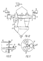
- Fig. I die Gesamtansicht einer erfindungsgemässen Anlage zur Wärmebehandlung eines polydispersen Gutes (Draufsicht, teilweiser Querschnitt);
- Fig. 2 den Schnitt nach der Linie II-II in Fig. I (Seitenansicht), gemäss der Erfindung:
- Fig. 3 die 2. Ausführungsform der erfindungsgemässen Anlage (Längsschnitt, Draufsicht);
- Fig. 4 den Schnitt nach der Linie IV-IV in Fig. 3 (Draufsicht), gemäss der Erfindung:
- Fig. 5 den Schnitt nach der Linie v-v in Fig. 3 (Seitenansicht), gemäss der Erfindung:
- Fig. 6 eine Einrichtung zum Verdrällen des Wärmeträgers und des polydispersen Gutes ( den Schnitt nach der Linie VI-VI in Fig. 3) gemäss der Erfindung;
- Fig. 7 den Schnitt nach der Linie VII-VII in Fig. 3 (Draufsicht), gemäss der Erfindung;
- Fig. 8 die 2. Ausführungsform des Zyklonabscheiders zum Abscheiden des getrockneten polydispersen Gutes (Seitenansicht, Längsschnitt), gemäss der Erfindung;
- Fig. 9 die 2. Ausführungsform der Einrichtung zum Ver= drallen des Wärmeträgers und des polydispersen Gutes (Seitenansicht, Längsschnitt), gemäss der Erfindung;
- Fig. 10 den Schnitt nach der Linie X-X in Fig. 9 (Draufsicht), gemäss der Erfindung:
- Fig. II einen Regler des Kühlmittelverbrauches (Ansicht von unten in Fig. 9), gemäss der Erfindung:
- Fig. I2 den Schnitt nach der Linie XII-XII in Fig. II, gemäss der Erfindung;
- Fig. I3 die 3. Ausführungsform der erfindungsgemässen Anlage (Seitenansicht, teilweiser Längsschnitt);
- Fig. 14 die 4. Ausführungsform der erfindungsgemässen Anlage (Seitenansicht, teilweiser Längsschnitt);
- Fig. I5 den Schnitt nach der Linie XV-XV in Fig. 14, gemäss der Erfindung;
- Fig. 16 den Schnitt nach der Linie XVI-XVI in Fig. 14, gemäss der Erfindung;
- Fig. 17 die 5. Ausführungsform der erfindungsgemässen Anlage (Seitenansicht, teilweiser Längsschnitt).
- I shows the overall view of a system according to the invention for the heat treatment of a polydisperse material (top view, partial cross section);
- 2 shows the section along the line II-II in Fig. I (side view), according to the invention:
- 3 shows the second embodiment of the system according to the invention (longitudinal section, top view);
- 4 shows the section along the line IV-IV in FIG. 3 (top view), according to the invention:
- 5 shows the section along the line vv in Fig. 3 (side view), according to the invention:
- 6 shows a device for swirling the heat transfer medium and the polydisperse material (the section along the line VI-VI in FIG. 3) according to the invention;
- 7 shows the section along the line VII-VII in FIG. 3 (top view), according to the invention;
- 8 shows the second embodiment of the cyclone separator for separating the dried polydisperse material (side view, longitudinal section), according to the invention;
- Fig. 9, the second embodiment of the device for V er = plump the heat carrier and the poly-dispersed material (side view, longitudinal section), according to the invention;
- 10 shows the section along the line XX in FIG. 9 (top view), according to the invention:
- II shows a regulator of coolant consumption (view from below in FIG. 9), according to the invention:
- Figure I2 shows the section along the line XII-XII in Figure II, according to the invention.
- I3 shows the third embodiment of the system according to the invention (side view, partial longitudinal section);
- 14 shows the fourth embodiment of the system according to the invention (side view, partial longitudinal section);
- I5 shows the section along the line XV-XV in Figure 14, according to the invention.
- 16 shows the section along the line XVI-XVI in FIG. 14, according to the invention;
- 17 shows the fifth embodiment of the system according to the invention (side view, partial longitudinal section).
Die Anlage zur Wärmebehandlung eines polydispersen Gutes enthält vier zylinderförmige Trockenkammern I, 2, 3, 4 (Fig. I), von denen jeweils zwei Trockenkammern I und 2, 3 und 4 längs der Erzeugenden der zylinderförmigen Seitenwände 5 unter Bildung von Kämmen 6 miteinander gekoppelt sind.The plant for the heat treatment of a polydisperse material contains four cylindrical drying chambers I, 2, 3, 4 (FIG. I), of which two drying chambers I and 2, 3 and 4 are coupled together along the generatrix of the cylindrical side walls 5 to form
Es ist eine Ausführungsform der Anlage möglich, die zwei zylinderförmige miteinander gekoppelte Trockenkammern enthält.An embodiment of the plant is possible which contains two cylindrical drying chambers coupled to one another.
Die zwei Paare der Trockenkammern I und 2, 3 und 4 befinden sich auf gegenüberliegenden Seiten und sind symmetrisch relativ zu Rohrleitungen 7, 8 für die Zuführung eines Wärmeträgers und des polydispersen Gutes angeordnet, welche tangential an die Seitenwand 5 jeder der gekoppelten Trockenkammern I, 2, 3, 5 senkrecht zu der durch die Kämme 6 geführten Kopplungsebene der Trokkenkammern I und 2, 3 und 4 befestigt sind. Die Eintrittsöffnungen 9 der Rohrleitungen 7, 8 für die Zuführung des Wärmeträgers und des polydispersen Gutes sind mit einer Einspeisevorrichtung zum Zuführen des polydispersen Nassgutes verbunden.The two pairs of drying chambers I and 2, 3 and 4 are located on opposite sides and are arranged symmetrically relative to
Als Wärmeträger verwendet man Luft, Wasserdampf, inerte Gase in Abhängigkeit von der technologischen Zweckbestimmung der Anlage.Air, water vapor, inert gases are used as the heat transfer medium depending on the technological purpose of the system.
Die Rohrleitungen 7. 8 für die Zuführung des Wärmeträgers und des polydispersen Gutes sind im Querschnitt rechtwinklig.The pipes 7. 8 for the supply of the heat transfer medium and the polydisperse material are rectangular in cross section.
Die Austrittsöffnungen II der Rohrleitungen 7, 8 für die Zuführung des Wärmeträgers und des polydispersen Gutes liegen symmetrisch relativ zu der durch die Kämme 6 geführten Kopplungsebene der Trockenkammern I und 2, 3 und 4. Die Austrittsöffnungen IIder Rohrleitungen 7, 8 sind in einem Abstand voneinander angeordnet, der 0,5 bis 1,5 des äquivalenten Durchmessers der Rohrleitungen 7, 8 für die Zuführung des Wärmeträgers und des polydispsersen Gutes beträgt.The outlet openings II of the
An den Wänden I2 jeder Rohrleitung 7, 8, welche sich an die Seitenwand 5 jeder der Trockenkammern I, 2, 3, 4 anschliessen, sind Öffnungen I3, I4 zum Überströmen des polydispersen Gutes vorgesehen, jede von denen mit einem schwenkbaren Schieber I5 versehen ist.On the walls I2 of each
An der oberen Stirnwand 16 (Fig. 2) jeder der Trokkenkammern I, 2, 3, 4 ist ein schneckenförmiger Austrittsstutzen I7 zur Ableitung des verbrauchten Wärmeträgers angebracht, der an den Saugstutzen eines Gebläses I8 angeschlossen ist.On the upper end wall 16 (Fig. 2) of each of the drying chambers I, 2, 3, 4, a screw-shaped outlet connection I7 is attached to discharge the used heat transfer medium, which is connected to the suction connection of a blower I8.
An der unteren Stirnwand 19 ist in jeder der Trokkenkammern I, 2, 3, 4 ein Zyklonabscheider 20 zum Abscheiden des getrockneten polydispersen Gutes koaxial befestigt. An der Befestigungsstelle der Zyklonabscheider 20 ist ein Vorsprung 2I gebildet der sich im Raum jeder der Trockenkammern I, 2, 3, 4 befindet. Ein im Oberteil jedes Zyklonabscheiders 20 angeordnetes Ausblaserohr 22 ist an der Achse 23 der Trockenkammern I, 2, 3. 4 entlang angeordnet und mit dem Austrittsstutzen I7 zur Ableitung des verbrauchten Wärmeträgers verbunden.A
Aus den Zyklonabscheidern 20 gelangt das..getrocknete polydisperse Gut in einen Bunker 24 und wird dann mittels einer Schnecke 25 zum Laden abgeleitet.The .. dried polydisperse material from the
Bei einer anderen Ausführungsvariante der Anlage zur Wärmebehandlung eines polydispersen Gutes ist jede der Rohrleitungen 7, 8 (Fig. 3) für die Zuführung des Wärmeträgers und des polydispersen Gutes mit ihrem Austrittsende tangential an zwei Vorsprünge 21 der Zyklonabscheider 20 der Trockenkammern I, 3 und 2, 4 befestigt. Die an die Wand I2 der Rohrleitungen 7, 8 angrenzende Kante 26 (Fig. 4) der Seitenwand 5 jeder der Trockenkammern I, 2, 3, 4 ist an den Aussenrand der zugeordneten Öffnung 13, I4 zum Überströmen des polydispersen Gutes angeschlossen.In another embodiment variant of the plant for the heat treatment of a polydisperse material, each of the pipes 7, 8 (FIG. 3) for the supply of the heat transfer medium and the polydisperse material with its outlet end is tangential to two
An der Verbindungsstelle jeder der Rohrleitungen 7, 8 für die Zuführung des Wärmeträgers und des polydispersen Gutes mit den Vorsprüngen 21 der Zyklonabscheider 20 sind Schlitzdüsen 27 mit einem schwenkbaren Schieber 28 vorgesehen.At the junction of each of the
An den Austrittsenden II der Rohrleitungen 7, 8, die an den Vorsprüngen 21 der Zyklonabscheider 20 befestigt sind, sind über die gesamte Höhe jeder der Trockenkammern I, 2, 3, 4 die Vorsprünge 21 der Zyklonabscheider 20 umgebende dreieckige strömungshauben 29 vorgesehen. Die dreieckige Strömungshauben 29 sind in Form einer gekröpften Platte ausgebildet.At the outlet ends II of the
Um die Einführung des schwebenden Gemisches aus Gas und polydispersem Gut in die Zyklonabscheider 20 durch regelbare Schlitzdüsen 27 gewährleisten zu können, sihd die Vorsprünge 21 der Zyklonabscheider 20 mit einer veränderlichen Höhe ausgeführt, die in Richtung von den dreieckigen Strömungshauben 29 zu der Schlitzdüse 27 hin stetig abnimmt.In order to be able to ensure the introduction of the floating mixture of gas and polydisperse material into the
Zur Behandlung eines polydispersen Gutes mit einem hohen Feuchtigkeitsgehalt und mit einer Neigung zur Klumpen- und Aggregatbildung, sind die Eintrittsenden 9 (Fig. 3) jeder der Rohrleitungen 7, 8 für die Zuführung des Wärmeträgers und des polydispersen Gutes mit zusätzlichen Rohrleitungen 30, 3I verbunden, welche durch Abzweigrohre 32, 33 einer Y -förmigen Rohrleitung unter Bildung einer ringförmigen Biegung 34 miteinander gekoppelt sind. Dabei ist der senkrecht verlaufende Übertragungsweg 35 der Y -förmigen Rohrleitung in der durch den Kamm 6 geführten Kopplungsebene der zylinderförmigen Trockenkammern I und 2, 3 und 4 gelegen. Der senkrecht verlaufende Übertragungsweg 35 ist mit Hilfe eines Flansches 36 mit einem Desintegrator 37 für das polydisperse Gut verbunden. Der Desintegrator 37 für das polydisperse Gut enthält einen Läufer 38, der durch einen Elektromotor 39 in Drehung versetzt wird. An der Achse 40 des Läufers 38 sind Schaufeln 41 befestigt. Der Desintegrator 37 (Fig. 5) für das polydisperse Gut ist mit einer Einspeisevorrichtung 42 zum Zuführen des polydispersen Nassgutes verbunden.For the treatment of a polydisperse material with a high moisture content and with a tendency to form lumps and aggregates, the inlet ends 9 (FIG. 3) of each of the
Die Einspeisevorrichtung 42 (Fig. 3) zum Zuführen des polydispersen Nassgutes enthält ein Auflockererband, das als an einer Welle 45 angeordnete Metallplatten 43, 44 ausgeführt ist, sowie eine Schnecke 46, mit deren Hilfe das polydisperse Gut weiter in den Desintegrator 37 zugeführt wird. Der Desintegrator 37 (Fig. 5) ist auch mit einem Heizapparat 47 verbunden, in dem der Wärmeträger mit dem durch einen Stutzen 48 (Fig. 3) zugeführten Dampf erwärmt wird.The feed device 42 (FIG. 3) for supplying the polydisperse wet material contains a loosening belt, which is designed as
In jedem Zyklonabscheider 20 zum Abscheiden des getrockneten polydispersen Gutes ist in seinem unteren Teil an der Achse 49 des Zyklonabscheiders 20 entlang ein zusätzlicher zylinderförmiger Stutzen 50 vorgesehen, der mit einer Einrichtung zum Verdralleg des Wärmeträgers ausgestattet ist. Die Einrichtung zum Verdrallen des Wärmeträgers ist in Gestalt eines tangential angeordneten Stutzens 5I (Fig. 6) ausgebildet. Die tangential angeordneten Stutzen 5I der in gekoppelten Trockenkammern I und 2, 3 und 4 angeordneten Zyklonabscheidern 20 sind paarweise an die Abzweigrohre 32, 33 (Fig. 7) derIn each
Y -förmigen Rohrleitung an der Kopplungsstelle dieser Abzweigrohre 32, 33 mit den Zusatzleitungen 30, 3I, d.h. an der Stelle der ringförmigen Biegung 34 angeschlossen, wo sich ein schwenkbarer Schieber 52 (Fig. 4, 7) befindet.Y-shaped pipeline at the coupling point of these
Im Unterteil der Zyklonabscheider 20 (Fig. 3) sind Bunker 53 untergebracht, in denen sich das getrocknete polydisperse Gut ansammelt und mittels der Schnecken 54 durch eine Rohrleitung 55 zum Laden abgeleitet wird.In the lower part of the cyclone separator 20 (FIG. 3) there are bunkers 53 in which the dried polydisperse material collects and is discharged by means of the
In den Unterteil jedes Zyklonabscheiders 20 kann ein Kühlmittel zugeführt werden; in diesem Fall ist der zusätzliche zylinderförmige Stutzen 50 (Fig. 8) mit der Atmosphäre oder mit einer Kühlmittelquelle (in der Zeichnung nicht wiedergegeben) verbunden.A coolant can be supplied in the lower part of each
Die Einrichtung zum Verdrallen des Wärmeträgers kann in Gestalt eines tangential angeordneten Stutzens 5I (Fig. 8, 6) sowie als eine Schaufeldose 56 (Fig. 9, IO) ausgeführt werden, die am oberen Ende des zusätzlichen zylinderförmigen Stutzens 50 angebracht ist.The device for swirling the heat transfer medium can be designed in the form of a tangentially arranged socket 5I (FIGS. 8, 6) and as a blade box 56 (FIG. 9, IO) which is attached to the upper end of the additional
Der zusätzliche zylinderförmige Stutzen 50 (Fig. 8, 9) jedes Zyklonabscheiders 20 ist mit einem Regler des Kühlmittelverbrauches versehen.The additional cylindrical connector 50 (Fig. 8, 9) of each
Der Regler des Kühlmittelverbrauches ist in Form eines schwenkbaren Schiebers 57 (Fig. 8, 6) ausgebildet. der im tangential angeordneten Stutzen 5I untergebracht ist.The regulator of the coolant consumption is designed in the form of a pivotable slide 57 (FIGS. 8, 6). which is accommodated in the tangentially arranged nozzle 5I.
Der Regler zur Regelung des Kühlmittelverbrauches kann in Gestalt von zwei Sektorenblenden 58 (Fig. II,I2) ausgeführt werden, die an der unteren Stirnwand des zusätzlichen zylinderförmigen Stutzens 50 mit der Möglichkeit einer festgelegten Drehung mittels einer Schraube 59 an einer Buchse 60 angebracht sind. Dabei ist eine der Sektorenblenden 58 an der unteren Stirnwand des zusätzlichen zylinderförmigen Stutzens 50 starr befestigt, während die andere Sektorenblende 58 mit der Möglichkeit einer festgelegten Drehung angeordnet und mittels einer Schraube 6I befestigt ist.The regulator for regulating the coolant consumption can be designed in the form of two sector diaphragms 58 (FIGS. II, I2), which are attached to a
Im Unterteil des Zyklonabscheiders 20 (Fig. 8) zum Abscheiden des getrockneten polydispersen Gutes ist an seiner Achse 49 entlang eine Einrichtung 62 zur Trennung der Ströme des Kühlmittels und des verbrauchten Wärmeträgers angeordnet, die in Gestalt eines durch die Drehung einer Zykloide um ihre eigene Spitzenlinie 63 gebildeten Drehkörpers ausgebildet ist. Die Einrichtung 62 zur Trennung der Ströme des Kühlmittels und des verbrauchten Wärmeträgers ist an einer Kolbenstange 64 mit der Möglichkeit einer festgelegten Bewegung an der Achse 49 des Zyklonabscheiders 20 entlang angebracht. Die Kolbenstange 64 befindet sich in einer Führungsbuchse 65, die mittels einer Schraube 66 befestigt ist.In the lower part of the cyclone separator 20 (FIG. 8) for separating the dried polydisperse material, a
Es ist eine dritte Ausführungsvariante der Anlage zur Wärmebehandlung eines polydispersen Gutes möglich, die eine.gleichmässige Verteilung des polydispersen Gutes über die Breite der Trockenkammern I, 2, 3, 4 (Fig. I3) gewährleistet; dabei ist mindestens eine der Stirnwände 16, I9 mit einer Neigung in Richtung zu der Anordnung der Öffnungen I3, I4 zum Überströmen des polydispersen Gutes hin ausgeführt.A third embodiment variant of the plant for the heat treatment of a polydisperse material is possible, which ensures a uniform distribution of the polydisperse material over the width of the drying chambers I, 2, 3, 4 (FIG. I3); at least one of the
Es ist eine vierte Ausführungsvariante der Anlage zur Wärmebehandlung eines polydispersen Gutes möglich, bei der jede der Trockenkammern I, 2, 3, 4 (Fig. 14, 15) wendelförmige Platten 67 zusätzlich enthält, die im Zwischenraum zwischen der Seitenwand 5 der Trockenkammer I, 2, 3, 4 und der Seitenwand 68 des im Raum der Trockenkammern I, 2, 3, 4 befindlichen Vorsprunges 2I des Zyklonabscheiders 20 befestigt sind. Die wendelformigen Platten 67 sind mit einem Wicklungsschritt ausgeführt, welcher der Höhe der Rohrleitungen 7, 8 für die ZufÜhrung des Wärmeträgers und des polydispersen Gutes gleich ist. Die wendelförmigen Platten 67 (Fig. 16), di in den gekoppelten Trockenkammern 1 und 2, 3 und 4 angeordnet si haben entgegengesetzte Windungsrichtungen. Dabe-i hat der Vorsprung 21 des Zyklonabscheiders 20 zum Abscheiden des getrockneten polydispersen Gutes eine die Höhe der aufgestellten wendelförmigen Platte 67 überschreitende Höhe.A fourth embodiment variant of the plant for the heat treatment of a polydisperse material is possible, in which each of the drying chambers I, 2, 3, 4 (FIGS. 14, 15) additionally contains
Die Austrittsenden II der Rohrleitungen 7, 8 für die Zuführung dem Wärmeträgers und des polydispersen Gutes sind im unteren Teil der Vorsprünge 2T der Zyklonabscheider 20 befestigt.The outlet ends II of the
Die wendelförmigen Platten 67 (Fig. I4) sind mit einem Ende an der oberen Wand 69 und mit ihrem anderen Ende an der unteren Wand 70 der Rohrleitungen 7, 8 für die Zuführung des Wärmeträgers und des polydispersen Gutes befestigt.The helical plates 67 (FIG. I4) are attached at one end to the
Dabei sind die wendelförmigen Platten 67 oberhalb der Rohrleitungen 7, 8 für die Zuführung des Wärmeträgers und des polydispersen Gutes angeordnet.The
Es ist eine fünfte Ausführungsvariante der Anlage möglich, wenn in jeder Trockenkammer I, 2, 3, 4 (Fig. I7) der Vorsprung 21 des Zyklonabscheiders 20 eine im wesentlichen der Höhe der Trockenkammer I, 2, 3, 4 gleiche Höhe hat. An der Seitenwand 68 des Vorsprunges 2I des Abscheiders 20 ist eine Schlitzdüse 7I zum Abfluss des verbrauchten Wärmeträgers und des getrockneten polydispersen Gutes in den Zyklonabscheider 20 vorgesehen. Die Rohrleitungen 7, 8 für die Zuführung des Wärmeträgers und des polydispersen Gutes sind im Oberteil des Vorsprunges 2I des Zyklonabscheiders 20 befestigt. während sich die wendelförmigen Platten 67 unterhalb der Rohrleitungen 7, 8 befinden. Die wendelförmigen Platten 67 sind mit einem Ende an dem Rand der Schlitzdüse 71 befestigt.A fifth variant of the system is possible if in each drying chamber I, 2, 3, 4 (FIG. I7) the
Die Anlage zur Wärmebehandlung eines polydispersen Gutes wird wie folgt betrieben.The plant for the heat treatment of a pol y disperse material is operated as follows.
Der vorgewärmte Wärmeträger und das polydisperse Nassgut werden aus der Einspeisevorrichtung 10 (Fig. 1, 2) in die Rohrleitungen 7. 8 eingeleitet. Die ent- standenen Ströme des schwebenden Gemisches aus Gas und polydispersem Gut werden in den Rohrleitungen 7 und 8 beschleunigt und in die Trockenkammern I und 2, 3 und 4 als gegenläufige, unter einem Winkel von 180° zueinander gerichtete Ströme zugeführt; sie stossen in der durch den Kamm 6 geführten Kopplungsebene der Trockenkammern 1 und 2, 3 und 4 zusammen.The preheated heat transfer medium and the polydisperse wet material are introduced from the feed device 10 (FIGS. 1, 2) into the pipelines 7. 8. The The existing streams of the floating mixture of gas and polydisperse are accelerated in the
In der Zusammenstosszone der Ströme des schwebenden Gemisches aus Gas und polydispersem Gut entsteht eine abklingende Schwingung der Teilchen des polydispersen Gutes, wonach diese Teilchen aus der Zusammenstosszone ausgetragen werden. In der Zusammenstosszone der Ströme, bei einem Abstand der Austrittsöffnungen I der Kanäle 7, 8 voneinander von 0,5 bis 1,5 äquivalenten Durchmessers der Rohrleitungen 7, 8 nimmt die Intensität der Wärme- und Stoffaustauschprozesse infolge einer Erhöhung der Zwischenphasengeschwindigkeiten und einer Vergrösserung der aktiven Oberfläche der Zwischenphasenberührung stark zu, die der geometrischen Oberfläche der Teilchen des polydispersen Gutes nahe ist.In the collision zone of the flows of the floating mixture of gas and polydisperse material, a decaying oscillation of the particles of the polydisperse material occurs, after which these particles are discharged from the collision zone. In the collision zone of the streams, at a distance of the outlet openings I of the
Dann werden die Ströme des schwebenden Gemisches aus Gas und polydispersem Gut unter Einwirkung des Zentrifugalkraftfeldes in den Trockenkammern I und 2, 3 und 4 in gegenläufigen Richtungen in einer zu der Zusammenstossebene der Ströme des schwebenden Gemisches aus Gas und polydispersem Gut senkrecht liegenden Ebene verdrallt.Then the flows of the floating mixture of gas and polydisperse are swirled under the action of the centrifugal force field in drying chambers I and 2, 3 and 4 in opposite directions in a plane perpendicular to the collision plane of the flows of the floating mixture of gas and polydisperse.
Unter Einwirkung der Zentrifugalkraft gelangt das polydisperse Gut aus den Trockenkammern I und 2, 3 und 4, in denen das Gebiet des zentrifugalen Hochdruckes herrscht durch die Öffnungen I3, 14 zum Uberströmen des polydispersen Gutes in die Rohrleitungen 7, 8, d.h. in das Gebiet des statischen Überdruckes. In den Rohrleitungen 7, 8 dringt das umlaufende polydisperse Gut unter Einwirkung der Trägheitskräfte in geradlinige Ströme des schwebenden Ausgangsgemisches aus Gas und polydispersem Gut ein, wird erneut beschleunigt und anschliessend beim nachfolgenden Zusammenstossen der gegenläufigen Ströme des schwebenden Gemisches aus Gas und polydispersem Gut gebremst. Dieser Prozess wird vielfach wiederholt, wodurch die Verweilzeit des polydispersen Gutes in den Zonen hochaktiver aerodynamischer Verhältnisse, nämlich den Zusammenstosszonen der geradlinigen gegenläufigen Ströme des schwebenden Gemisches aus Gas und polydispersem Gut stark verlängert und der Koeffizient des Wärme- und Stoffaustausches im Strom des polydispersen Gutes erhöht werden. Nach einem mehrfachen Umlauf des polydispersen Gutes aus dem Raum der Trockenkammern I, 2, 3, 4 in die Rohrleitungen 7, 8 wird das getrocknete polydisperse Gut in radial abfliessenden Strömen aus den Trockenkammern I, 2, 3, 4 in die Zyklonabscheider 20 zum Abscheiden des getrockneten polydispersen Gutes zugeführt. Zum Abscheiden des getrockneten polydispersen Gutes aus dem verbrauchten Wärmeträger wird in den Zyklonabscheidern 20 die kinetische Energie der Ströme des schwebenden Gasgemisches unmittelbar in den Trockenkammern I, 2. 3, 4 ausgenutzt. Aus den Zyklonabscheidern. 20 gelangt das getrocknete polydisperse Gut in den Bunker 24 und wird dann mittels der Schnecke 25 zum Laden weitergeleitet. Der verbrauchte Wärmeträger wird durch das Ausblaserohr 22 und den schneckenförmigen Austrittsstutzen 17 mittels des Gebläses 18 in die Atmosphäre oder zur sanitären Reinigung abgesaugt.Under the action of the centrifugal force, the polydisperse material arrives from the drying chambers I and 2, 3 and 4, in which the area of the centrifugal high pressure prevails through the openings I3, 14 to overflow the polydisperse material into the
Die Einstellung der Anlage auf einen optimalen aerodynamischen Betrieb, d.h., die Regelung der Verweilzeit des polydispersen Gutes in der Zone der Wärmebehandlung erfolgt durch eine Regelung der Rückführung des polydispersen Gutes aus den Trockenkammern I, 2, 3, 4 in Rohrleitungen 7, 8 für die Zuführung des Wärmeträgers und des polydispersen Gutes mittels der schwenkbaren Schieber 15. Bei einem weiteren Öffnen der schwenkbaren Schieber I5 der Öffnungen I3, 14 zum Überströmen des polydispersen Gutes nimmt die Anzahl der Umlauf - zyklen des schwebenden Gemisches aus Gas und polydispersem Gut zu, die Konzentration des polydispersen Gutes in der Zone hochaktiver aerodynamischer Verhältnisse erhöht sich und der Wärme- und Stoffaustauschprozess wird intensiviert. Dabei vergrössert sich jedoch der aerodynamische Widerstand der Anlage.The setting of the system for optimal aerodynamic operation, that is, the regulation of the residence time of the polydisperse material in the zone of the heat treatment is carried out by regulating the return of the polydisperse material from the drying chambers I, 2, 3, 4 in
Zur Behandlung eines polydispersen Gutes mit einer Neigung zur Klumpenbildung wird die Anlage in der 2. Ausführungsvariante eingesetzt.For the treatment of a polydisperse material with a tendency to form lumps, the system is used in the second embodiment variant.
Der in dem Heizapparat 47 (Fig. 3) erwärmte Wärmeträger und das polvdisperse Nassgut werden aus der Einspeisevorrichtung 42 mittels der Schnecke 46 in den Desintegrator 37 für das polydisperse Gut zugeführt. Beim Betrieb der Einspeisevorrichtung 42 vom Schneckentyp mit dem polydispersen Nassgut entstehen unvermeidlich Klumpen aus dem polydispersen Gut. Im Desintegrator 37 (Fig. 4) tritt das polydisperse Gut mit den umlaufenden Schaufeln 4I des Läufers 38 in Wechselwirkung, wird aufgelockert und mit dem Wärmeträger in den senkrecht verlaufenden Übertragungsweg 35 (Fig. 3) der Y -förmigen Rohrleitung ausgetragen. Durch eine Anordnung des Läufers 38 unterhalb des Übertragungsweges 35, bei der die Achse 40 des Läufers 38 senkrecht zu der Kopplungsebene der Trockenkammern I, 2, 3. 4 verläuft wird eine gleichmäseige Verteilung des schwebenden Gemisches aus Gas und polydispersem Gut zwischen den Abzweigrohren 32, 33 der Y -förmigen Rohrleitung, den zusätzlichen Rohrleitungen 30, 3I und den Rohrleitungen 7, 8 gewährleistet. In der Verbindungszone der Abzweigrohre 32, 33 der Y -förmigen Rohrleitung mit den zusätzlichen Rohrleitungen 30, 3I in der ringförmigen Biegung 34 findet eine Fraktionierung des schwebenden Gemisches aus Gas und polydispersem Gut nach der Korngrösse statt, die unterschiedlicher Trocknungsdauer bedürfen. Die Feinfraktion des polydispersen Gutes bewegt sich in Richtung zu der Drehachse des schwebenden Gasgemisches hin über die ringförmige Biegung 34 und gelangt durch den tangential angeordneten Stutzen 5I über den zylinderförmigen Stutzen 50 in den Zyklonabscheider 20 zur Trocknung. Die Menge des schwebenden feindispersen Gasgemisches und die Grenzkorngrösse der Teilchen des polydispersen Gutes werden durch die schwenkbaren Schieber 52 geregelt. Das schwebende gemisch aus Gas und der grobdispersen Fraktion des polydispersen Gutes wird in die Rohrleitungen 7, 8 zugeführt. Nach dem Zusammenstossen der gegenläufigen Ströme des polydispersen Gutes in der Kopplungsebene der Trockenkammern I und 2, 3 und 4 fliesst das Gasgemisch in durch die Strömungshauben 29 geformten, streng tangential gerichteten Strömen in die Trockenkammern I, 2, 3, 4 ab, in denen es in gegenläufige Richtungen gedreht wird. In den Trockenkammern I und 2, 3 und 4 erfolgt die Wärmebehandlung ähnlich wie oben beschrieben. Der Strom des schwebenden Gemisches aus Gas und polydispersem Gut dreht sich in den von den Seitenwänden der Vorsprünge 21 der Zyklonabscheider 20 und den Seitenwänden 5 der Trockenkammern I, 2, 3, 4 gebildeten Räumen der Trockenkammern I, 2, 3, 4, wonach die Teilchen des polydiapersen Gutes mit einer höheren Trägheit, d.h., die grösseren und weniger getrockneten Teilchen, in die Rohrleitungen 7, 8 durch die Öffnungen 13, I4 zum Überströmen des polydispersen Gutes zum nachfolgenden Zusammenstossen in Gegenströmen des schwebenden Gemisches aus Gas und polydispersem Gut zurückgeführt, während die getrockneten Teilchen des polydispersen Gutes durch die Schlitzdüse 27 in tangential gerichteten Strömen in den Zyklonabscheider 20 ausgetragen werden, wo das polydisperse Gut und der verbrauchte Wärmeträger voneinander getrennt werden, VerdrallenThe heat transfer medium heated in the heating apparatus 47 (FIG. 3) and the polydisperse wet material are fed from the
Die Einrichtungen zum des Wärmeträgers und des polydispersen Gutes, ausgebildet in Form eines tangential angeordneten Stutzens 5I (Fig. 8, 6) oder einer Schaufeldose 56 (Fig. 9, 10), sorgen für das Einführen des verdrallten Stromes des schwebenden Gemisches aus Gas und polydispersem Gut in den kegelförmigen Teil der Zyklonabscheider 20 (Fig. 9) durch den zusätzlichen zylinderförmigen Stutzen 50.The devices for the heat transfer medium and the polydisperse material, designed in the form of a tangentially arranged connection piece 5I (FIGS. 8, 6) or one Paddle box 56 (FIGS. 9, 10) ensure the introduction of the swirled flow of the floating mixture of gas and polydisperse material into the conical part of the cyclone separator 20 (FIG. 9) through the additional
Das aus dem Wärmeträger abgeschiedene getrocknete polydisperse Gut wird in absteigender Schraubenströmung in den Unterteil der Zyklonabscheider 20, in die Abkühlzone 72 des polydispersen Gutes ausgetragen, die sich unterhalb der Einrichtung 62 zur Trennung der Ströme des Kühlmittels und des verbrauchten Wärmeträgers voneinander befindet. Das Kühlmittel wird durch den zylinderförmigen Stutzen 50 zugeführt und im Durchströmen durch den Tangentialstutzen 5I in eine Drehbewegung versetzt. In der Abkühlzone 72 tritt der unter Einwirkung der Trägheitskraft aus der oberhalb der Vorrichtung 62 liegenden Abscheidezone 73 fliessende spiralförmige Strom des polydispersen Gutes mit dem sich drehenden gegenläufig gerichteten Strom der Kühlluft in aktive Wechselwirkung. Dann gelangt das abgekühlte polydisperse Gut in den Bunker 24. Das verbrauch- te Kühlmittel gelangt unter Überwindung des Strömungswiderstandes der Einrichtung 62 aus der Abkühlzone 72 in den Oberteil der Zyklonabscheider 20, d.h., in die Abscheidezone 73 des polydispersen Gutes, wo es mit dem verbrauchten Wärmeträger vermischt und in einem gemeinsamen spiralförmigen Strom durch das Ausblaserohr 22 (Fig. 3) ausgetragen wird. Der gemeinsame Gasstrom wird dann zur sanitären Reinigung zugeführt, die in der Regel im Nassverfahren durchgeführt wird.The dried polydisperse material separated from the heat transfer medium is discharged in descending screw flow into the lower part of the
Die Einstellung der Anlage auf optimale technologische Bedingungen für die Abkühlung des polydispersen Gutes wird durch eine Änderung von zwei Kennwerten u.z. der Länge 10 der Abkühlzone 72 (Fig. 9) des polydispersen Gutes und des Durchsatzes des Kühlmittels vor-0 genommen. Die Länge lo der Abkühlzone 72 des plydispersen Gutes wird durch eine Änderung der axialen Lage der Einrichtung 62 geändert. Bei einer Verschiebung der Einrichtung 62 in Richtung zu dem Ausblaserohr 22 des Zyklonabscheiders 20 hin wird die Länge der Abkühlzone 72 des polydispersen Gutes vergrössert, wodurch der Prozess der Abkühlung intensiver abläuft, während das Abscheidevermögen der Zyklonabscheider 20 bei einer Verminderung der Länge 10 der Abscheidezone 73 des polydispersen Gutes sinkt.The setting of the system to optimum technological conditions for the cooling of the polydisperse material is by a change of two characteristic values of the length uz 1 0 the cooling zone 72 (Fig. 9) of the poly-dispersed material and the flow rate of the coolant taken before-0. The length l o of the cooling
Die Änderung der Kühlmittelverbrauchsmenge wird mit Hilfe des schwenkbaren Schiebers 57 (Fig. 6) erzielt, wenn der Regler des Kühlmittelverbrauches in Form eines, tangential angeordneten Stutzens 51 ausgeführt ist, sowie durch eine Anderung des Schwenkungswinkels der Sektorenblenden 58 (Fig. I) vorgenommen, wenn der Regler als zwei Sektorenblenden 58 ausgeführt ist.The change in the coolant consumption quantity is achieved with the aid of the pivotable slide 57 (FIG. 6) if the regulator of the coolant consumption is designed in the form of a tangentially arranged
Die Xnderung der Kühlmittelverbrauchsmenge führt zu einer Änderung der Bilanzverhältnisse zwischen dem Abkühlungsprozess und der Hydrodynamik des sich drehenden Stromes des abzukühlenden polydispersen Gutes. Da bei geringen Kühlmittelverbrauchsmengen die dynamische Einwirkung des Kühlmittels auf das polydisperse Gut unbedeutend ist, findet praktisch keine Anderung der strangförmigen Struktur des Stromes des polydispersen Gutes statt, infolgedessen die Abkühlungsintensität des polydispersen Gutes auch gering ist. Bei einer Vergrösserung der Kühlmittelverbrauchsmenge erhöhen sich die Drehgeschwindigkeit und die dynamische Einwirkung des Kühlmittels auf das abzukühlende polydisperse Gut. Die Geschwindigkeit des Stromes des polydispersen Gutes nimmt ab und in der Abkühlzone 72 (Fig. 9) des polydispersen Gutes entsteht eine stabile ringförmige Schicht, die mit dem Kühlmittel wirksam zusammenwirkt. Solche Betriebsverhältnisse sichern ein maximalesThe change in the amount of coolant consumed leads to a change in the balance between the cooling process and the hydrodynamics of the rotating stream of the polydisperse to be cooled. Since the dynamic influence of the coolant on the polydisperse material is insignificant when the coolant consumption amounts are low, there is practically no change in the strand-like structure of the flow of the polydisperse material, as a result of which the cooling intensity of the polydisperse material is also low. If the amount of coolant consumed is increased, the speed of rotation and the dynamic effect of the coolant on the polydisperse material to be cooled increase. The speed of the flow of the polydisperse material decreases and in the cooling zone 72 (FIG. 9) of the polydisperse material a stable annular layer is created which interacts effectively with the coolant. Such operating conditions ensure a maximum
Haltevermögen der Abkühlzone 72 des polydispersen Gutes (Menge des gleichzeitig in der Zone 72 verweilenden polydispersen Gutes).Holding capacity of the
Bei einer weiteren Vergrösserung der Kühlmittelverbrauchsmenge findet ein bedeutendes sekundäres Austragen des polydispersen Gutes in die Abscheidezone 73 des polydispersen Gutes statt. Dabei wird die Wirksamkeit des Betriebes der Zyklonabscheider 20 vermindert.With a further increase in the amount of coolant consumed, the secondary discharge of the polydisperse material into the
Bei der 3. Ausführungsvariante der Anlage zur Wärmebehandlung eines polydispersen Gutes, in der mindestens eine der Stirnwände 16, I9 (Fig. 13) mit einer Neigung in Richtung zu der Anordnung der Öffnungen 13, 14 zum Uberströmen des polydispersen Gutes ausgeführt ist, wird eine gleichbleibende Drehgeschwindigkeit des. Stromes des schwebenden Gemisches aus Gas und polydispersem Gut auf dem Umfang der Trockenkammern I, 2, 3, 4 (Fig. 2) gewährleistet, die der linearen Geschwindigkeit des Stromes im Bereich der Kämme 6 der Trockenkammern 1, 2, 3, 4 gleich ist. Das ist darauf zurückzuführen, dass die Querschnittsfläche des sich in den Trockenkammern I, 2, 3, 4 drehenden Stromes des schwebenden Gemisches aus Gas und polydispersem Gut in Richtung von den Kämmen 6 zu den Öffnungen 13, 14 zum Uberströmen des polydispersen Gutes hin abnimmt. Dadurch werden die Verluste der kinetischen Energie ausgeglichen, welche durch die Reibung der Teilchen des polydispersen Gutes an den Seitenwänden 5 (Fig. I) der Trockenkammern I, 2, 3, 4 und den radialen Abfluss des verbrauchten Wärmeträgers in die Zyklonabscheider 20 eintreten.In the third variant of the installation for the heat treatment of a polydisperse material, in which at least one of the
Bei der Wärmebehandlung eines monodispersen Gutes (die Teilchen des polydispersen Gutes sind von einer annäherend gleichen Korngrösse) wird zweckmässigerweise die obere Stirnwand 16 (Fig. 13) jeder Trockenkammer I, 2. 3, 4 (Fig. 2) mit einer Neigung in Richtung zu der Anordnung der Öffnungen 13, I4 hin ausgeführt, weil die Wahrscheinlichkeit eines Aufalls von grossen Teilchen des polydispersen Gutes aus dem sich drehenden Strom des schwebenden Gasgemisches im Bereich der Öffnungen 13, I4 recht gering ist.When heat-treating a monodisperse material (the particles of the polydisperse material are of approximately the same grain size), the upper end wall 16 (FIG. 13) of each drying chamber I, 2. 3, 4 (FIG. 2) is expediently inclined in the direction the arrangement of the openings 13, I4 out because the probability of large particles of the polydisperse material falling out of the rotating Current of the floating gas mixture in the area of the openings 13, I4 is quite low.
Beim Trocknendes Gutes einer polydispersen Zusammensetzung mit einem mittleren äquivalenten Durchmesser der Fraktionen von über (2 - 3)·104 m werden zweckmässigerweise die obere und die untere Stirnwand 16, I9 (Fig. I3) jeder Trockenkammer mit einer symmetrischen Neigung in Richtung zu der Anordnung der Öffnungen 13, 14 angebracht, um einen Ausfall von grossen Teilchen des polydispersen Gutes aus dem sich drehenden Strom des schwebenden Gasgemisches aus schliessen zu können. In diesem Fall werden sogar die besonders grossen Teilchen des polydispersen Gutes zu einem erneuten Umlauf in die Kanäle 7, 8 geleitet.When drying the material of a polydisperse composition with an average equivalent diameter of the fractions of over (2-3) × 10 4 m, the upper and
Bei der Wärmebehandlung von polydispersen Stoffen mit einem hohen Feuchtigkeitsgehalt oder bei der Durchführung von Hochtemperaturprozessen beim Rösten, bei der Pyrolyse wird die Anlage in der 4. Ausführungsvariante eingesetzt, in der ein Hochtemperatur-Wärmeträger mit einer Temperatur von 300° bis 800°C verwendet wird. Die gegenläufig gerichteten, über die Rohrleitungen 7, 8 (Fig. I4, 17) zugeführten Ströme des schwebenden Gemisches aus Gas und polydispersem Gut stossen miteinander mehrfach in der Anordnungsebene der Kämme 6 der Trockenkammern I und 2, 3 und 4 in den Zonen 74 an jeder Wicklung der wendelförmigen Platten 67 zusammen. Das schwebende Gemisch aus Gas und polydispersem Gut dreht sich über die spiralförmigen Kanäle ohne rückläufiges Vermischen, d.h., es fehlt ein Rückumlauf sowohl des Wärmeträgers, als auch der Teilchen des polydispersen Gutes. Dadurch kann die Wärmeenergie des Wärmeträgers maximal ausgenutzt und der Energieaufwand reduziert werden.In the heat treatment of polydisperse substances with a high moisture content or when carrying out high-temperature processes during roasting, during pyrolysis, the fourth version of the system is used, in which a high-temperature heat transfer medium with a temperature of 300 ° to 800 ° C is used . The oppositely directed streams of the floating mixture of gas and polydisperse material supplied via the pipes 7, 8 (FIGS. 14, 17) bump into each other several times in the arrangement level of the
Dann werden der verbrauchte Wärmeträger und das getrocknete polydisperse Gut durch die obere Stirnseite des Vorsprunges 2I (Fig. I4) oder durch die Schlitzdüse 71 (Fig. 17) an der Seitenwand 68 des Vorsprungs 2I in den Zyklonabscheider 20 zugeführt.The spent heat transfer medium and the dried polydisperse material are then passed through the upper end face of the projection 2I (FIG. 14) or through the slot nozzle 71 (FIG. 17) on the
Im weiteren wird die Anlage ähnlich wie oben beschrieben betrieben.In addition, the system is operated similarly to that described above.
Die Anordnung der wendelförmigen Platten 67 oberhalb der Rohrleitungen 7, 8 (Fig. I4) für die Zuführung des Wärmeträgers und des polydispersen Gutes oder unterhalb dieser Rohrleitungen 7, 8 (Fig. 17) ist von ausschlaggebender Bedeutung für die Bewegungsrichtung des Stromes des schwebenden Gemisches aus Gas und polydispersem Gut jeweils im auf- oder absteigenden spiralförmigen,durch die Wicklungen der wendelförmigen Platte 67 gebildeten Kanal.The arrangement of the
Im Falle, wenn die Wärmebehandlung eines grobdispersen Gutes durchgeführt werden soll, wird das Gut von den oberen Niveauhöhen der Trockenkammern 1, 2, 3, 4 zugeführt, d.h., die wendelförmigen Platten sind unterhalb der Rohrleitungen 7, 8 angeordnet.In the case where the heat treatment of a coarsely disperse material is to be carried out, the material is fed from the upper level heights of the drying
Zur Bewegung des schwebenden Gemisches aus Gas und polydispersem Gut durch die spiralförmigen Kanäle zwischen den Windungen der wendelförmigen Platten 67 wird die kinetische Energie von tangential gerichteten Strömen ausgenutzt, die nach dem Zusammenstossen in der Zone 74 in der Kopplungsebene der Trockenkammern I und 2. 3 und 4 ausgebildet werden, wodurch der Strömungswiderstand der Anlage vermindert werden kann.To move the floating mixture of gas and polydisperse material through the spiral channels between the turns of the
Durch die Verwendung der Anlage zur Wärmebehandlung eines polydispersen Gutes kann der Strömungswiderstand der Anlage um das I,2 bis I,4fache vermindert werden. Bei der Wärmebehandlung eines grobdispersen Gutes kann ein Hochtemperatur-Wärmetrager verwendet werden; dabei wird der Prozess der Wärmebehandlung bei einer praktisch vollständigen Sättigung des verbrauchten Wärmeträgers mit Nassdampf geführt. Dadurch kann der Energieaufwand um 30 bis 40% herabgesetzt werden.By using the plant for the heat treatment of a polydisperse material, the flow resistance of the plant can be reduced by 1.2 to 1.4 times. A high-temperature heat transfer medium can be used for the heat treatment of a coarsely disperse material; the process of heat treatment is carried out when the used heat carrier is practically completely saturated with wet steam. As a result, the energy expenditure can be reduced by 30 to 40%.
Die vorliegende Erfindung kann ihre Anwendung in der Lebensmittel-. Chemie-, pharmazeutischen. Zellstoff-und Papierindustrie, bei der Herstellung von Baustoffen, in Zweigen des Agrar-Industrie-Komplexes zur Trocknung von Milchzucker, Stärke, Vinylchlorid-Mischpolymerisaten, medizinischen Präparaten, der zerkleinerten Papiermasse, Sägemehl, Torf, Sand, Behaarung und Gefieder der Schlachtiere, der zerkleinerten Grasmasse sowie zum Rösten von Magnesit, Dolomit, zur Abkühlung polydisperser Schüttgüter finden.The present invention can be used in food. Chemical, pharmaceutical. Pulp and paper industry, in the production of building materials, in branches of the agricultural industry complex for drying milk sugar, starch, vinyl chloride copolymers, medical preparations, the shredded paper pulp, sawdust, peat, sand, hair and plumage of the slaughtered animals crushed grass mass as well as for roasting magnesite, dolomite, for cooling polydisperse bulk materials.
Claims (19)
Rohrleitungen (30, 31) verbunden sind, an welcher Stelle ein schwenkbarer Schieber (57) abstandsgleich angeordnet ist.12. Plant according to claim II, characterized in that the tangentially arranged connecting piece (51) of each cyclone separator (20) for separating the dried polydisperse material in pairs with the branch pipes (32, 33) of the Y-shaped pipeline at its coupling point with the additional
Pipes (30, 31) are connected, at which point a pivotable slide (57) is arranged at the same distance.
Applications Claiming Priority (1)
| Application Number | Priority Date | Filing Date | Title |
|---|---|---|---|
| PCT/SU1989/000011 WO1990008296A1 (en) | 1989-01-18 | 1989-01-18 | Installation for heat treatment of polydispersed materials |
Publications (2)
| Publication Number | Publication Date |
|---|---|
| EP0406421A1 true EP0406421A1 (en) | 1991-01-09 |
| EP0406421A4 EP0406421A4 (en) | 1991-07-03 |
Family
ID=21617385
Family Applications (1)
| Application Number | Title | Priority Date | Filing Date |
|---|---|---|---|
| EP19890904299 Withdrawn EP0406421A4 (en) | 1989-01-18 | 1989-01-18 | Installation for heat treatment of polydispersed materials |
Country Status (4)
| Country | Link |
|---|---|
| EP (1) | EP0406421A4 (en) |
| JP (1) | JPH03504155A (en) |
| DK (1) | DK222890A (en) |
| WO (1) | WO1990008296A1 (en) |
Cited By (1)
| Publication number | Priority date | Publication date | Assignee | Title |
|---|---|---|---|---|
| EP3798559A1 (en) * | 2019-10-15 | 2021-03-31 | Plasmaq - Maquinas e Equipamentos Para a Industria de Plasticos, Lda | Equipment for breaking and drying plastic film waste to recycle |
Families Citing this family (2)
| Publication number | Priority date | Publication date | Assignee | Title |
|---|---|---|---|---|
| DE4421714A1 (en) | 1994-06-21 | 1996-01-04 | Bosch Gmbh Robert | Fuel injection system |
| GB0407440D0 (en) | 2004-04-01 | 2004-05-05 | Eja Ltd | Safety switch assembly |
Citations (5)
| Publication number | Priority date | Publication date | Assignee | Title |
|---|---|---|---|---|
| US2494153A (en) * | 1945-02-23 | 1950-01-10 | Micronizer Company | Drying and pulverizing method and apparatus |
| US2520747A (en) * | 1945-08-22 | 1950-08-29 | Broek Wouter Van Den | Fluid current drier for grass and the like |
| US3329418A (en) * | 1965-03-30 | 1967-07-04 | Fluid Energy Proc & Equipment | Apparatus for treating wet solid and semi-solid materials in a fluid stream |
| US3339286A (en) * | 1965-03-11 | 1967-09-05 | Fluid Energy Proc And Equipmen | Method and apparatus for drying wet pulverulent material in a gaseous path |
| SU983412A2 (en) * | 1981-06-19 | 1982-12-23 | Могилевский технологический институт | Unit for druing solutions and suspensions |
Family Cites Families (3)
| Publication number | Priority date | Publication date | Assignee | Title |
|---|---|---|---|---|
| SU870874A1 (en) * | 1980-01-23 | 1981-10-07 | Могилевский технологический институт | Unit for drying solutions and suspensions |
| SU1044920A1 (en) * | 1982-06-11 | 1983-09-30 | Могилевский технологический институт | Suspension drying plant |
| FR2543280B1 (en) * | 1983-03-23 | 1987-12-04 | Gaz De France | METHOD AND PLANT FOR HEAT TREATMENT OF DIVIDED PRODUCTS |
-
1989
- 1989-01-18 EP EP19890904299 patent/EP0406421A4/en not_active Withdrawn
- 1989-01-18 WO PCT/SU1989/000011 patent/WO1990008296A1/en not_active Application Discontinuation
- 1989-01-18 JP JP50384989A patent/JPH03504155A/en active Pending
-
1990
- 1990-09-17 DK DK222890A patent/DK222890A/en not_active Application Discontinuation
Patent Citations (5)
| Publication number | Priority date | Publication date | Assignee | Title |
|---|---|---|---|---|
| US2494153A (en) * | 1945-02-23 | 1950-01-10 | Micronizer Company | Drying and pulverizing method and apparatus |
| US2520747A (en) * | 1945-08-22 | 1950-08-29 | Broek Wouter Van Den | Fluid current drier for grass and the like |
| US3339286A (en) * | 1965-03-11 | 1967-09-05 | Fluid Energy Proc And Equipmen | Method and apparatus for drying wet pulverulent material in a gaseous path |
| US3329418A (en) * | 1965-03-30 | 1967-07-04 | Fluid Energy Proc & Equipment | Apparatus for treating wet solid and semi-solid materials in a fluid stream |
| SU983412A2 (en) * | 1981-06-19 | 1982-12-23 | Могилевский технологический институт | Unit for druing solutions and suspensions |
Non-Patent Citations (3)
| Title |
|---|
| Drying Technology vol. 7, no. 2, Juni 1989, New York, US Seiten 219-266; Kudra et al: "IMPINGEMENT STREAM DRYERS FOR PARTICLES AND PASTES" * |
| See also references of WO9008296A1 * |
| SOVIET INVENTIONS ILLUSTRATED, Section P/Q, Week K43, 7 Dec. 83, DERWENT PUBLICATIONS LTD., LONDON GB, class Q, no. 83-799779/43 & SU-A-983412 (MOGIL TECHN INST) 23 Dec. 82 * |
Cited By (1)
| Publication number | Priority date | Publication date | Assignee | Title |
|---|---|---|---|---|
| EP3798559A1 (en) * | 2019-10-15 | 2021-03-31 | Plasmaq - Maquinas e Equipamentos Para a Industria de Plasticos, Lda | Equipment for breaking and drying plastic film waste to recycle |
Also Published As
| Publication number | Publication date |
|---|---|
| JPH03504155A (en) | 1991-09-12 |
| WO1990008296A1 (en) | 1990-07-26 |
| EP0406421A4 (en) | 1991-07-03 |
| DK222890A (en) | 1990-11-16 |
| DK222890D0 (en) | 1990-09-17 |
Similar Documents
| Publication | Publication Date | Title |
|---|---|---|
| EP1956326B1 (en) | Device for removing fluids and/or solids | |
| DE69720114T2 (en) | Two-stage spray dryer | |
| EP3486591B1 (en) | Fluidized bed evaporation drier | |
| DD249412A5 (en) | METHOD AND DEVICE FOR DRYING A LIQUID MATERIAL | |
| DE69633192T2 (en) | METHOD AND DEVICE FOR DRYING POWDERED MATERIAL | |
| DE3314887A1 (en) | GAS DISTRIBUTION FLOOR FOR DRYERS OR THE LIKE WITH CIRCULATING FLUID BED | |
| EP2326900B1 (en) | Method and device for drying biomass | |
| DE2129186A1 (en) | Method and device for the fluidization of particulate materials | |
| DE2335514A1 (en) | Hot air treatment in fluidised bed - esp. of heat sensitive material with air inlets above bed floor | |
| EP0597092B1 (en) | Apparatus for obtaining granulated product | |
| DE2634072B2 (en) | Drum dryer | |
| DE2155240B2 (en) | Device for continuous treatment, e.g. by drying or cooling dusty, powdery and granular material | |
| EP0406421A1 (en) | Installation for heat treatment of polydispersed materials | |
| DD217004A1 (en) | DEVICE FOR RADIANT-LAYER DRYING OF STICKY-CERAMIC AND THERMOLATIVE SUBSTANCES | |
| DE897977C (en) | Device for drying goods by means of hot gases | |
| DE2555553A1 (en) | METHOD OF DRYING WET PARTICLES AND CENTRIFUGAL DRYING SYSTEM | |
| DE2950749C2 (en) | ||
| EP0197171A1 (en) | Low-temperature dryer for pressed fibrous material | |
| DE19538048C2 (en) | Device for drying and heating coal to be fed from a coke oven | |
| DE3642276C2 (en) | ||
| DE2634513C3 (en) | Device for drying particulate matter in a cylindrical chamber | |
| DE2745179A1 (en) | Mixing drying and granulating tower - has inert gas and moisture injected into bottom chamber with paddles and cutters | |
| DE4326410A1 (en) | Dewatering device for dewatering sludge | |
| DE2243670A1 (en) | PROCESS AND EQUIPMENT FOR CONTINUOUS DRYING OF GRAINY MATERIALS IN A FLUIDED BED | |
| AT263526B (en) | Device for the treatment of pastes derived from plant products by means of bleaching reagents |
Legal Events
| Date | Code | Title | Description |
|---|---|---|---|
| PUAI | Public reference made under article 153(3) epc to a published international application that has entered the european phase |
Free format text: ORIGINAL CODE: 0009012 |
|
| 17P | Request for examination filed |
Effective date: 19900919 |
|
| AK | Designated contracting states |
Kind code of ref document: A1 Designated state(s): CH DE FR GB LI NL SE |
|
| A4 | Supplementary search report drawn up and despatched |
Effective date: 19910516 |
|
| AK | Designated contracting states |
Kind code of ref document: A4 Designated state(s): CH DE FR GB LI NL SE |
|
| STAA | Information on the status of an ep patent application or granted ep patent |
Free format text: STATUS: THE APPLICATION HAS BEEN WITHDRAWN |
|
| 18W | Application withdrawn |
Withdrawal date: 19910819 |
|
| R18W | Application withdrawn (corrected) |
Effective date: 19910819 |