EP0406325B2 - Procede et dispositif pour remplir des vitres isolantes de gaz lourd - Google Patents
Procede et dispositif pour remplir des vitres isolantes de gaz lourd Download PDFInfo
- Publication number
- EP0406325B2 EP0406325B2 EP89905079A EP89905079A EP0406325B2 EP 0406325 B2 EP0406325 B2 EP 0406325B2 EP 89905079 A EP89905079 A EP 89905079A EP 89905079 A EP89905079 A EP 89905079A EP 0406325 B2 EP0406325 B2 EP 0406325B2
- Authority
- EP
- European Patent Office
- Prior art keywords
- gas
- glass plate
- spacer
- glass plates
- glass
- Prior art date
- Legal status (The legal status is an assumption and is not a legal conclusion. Google has not performed a legal analysis and makes no representation as to the accuracy of the status listed.)
- Expired - Lifetime
Links
- 239000011521 glass Substances 0.000 title claims abstract description 314
- 238000000034 method Methods 0.000 title claims description 54
- 125000006850 spacer group Chemical group 0.000 claims description 97
- 238000005452 bending Methods 0.000 claims description 15
- 230000001154 acute effect Effects 0.000 claims description 4
- 230000000630 rising effect Effects 0.000 claims description 3
- 230000000452 restraining effect Effects 0.000 claims 1
- 239000007789 gas Substances 0.000 description 119
- 238000005429 filling process Methods 0.000 description 15
- 238000004519 manufacturing process Methods 0.000 description 8
- 239000000203 mixture Substances 0.000 description 6
- 239000000853 adhesive Substances 0.000 description 5
- 230000001070 adhesive effect Effects 0.000 description 5
- 230000008901 benefit Effects 0.000 description 5
- 239000002274 desiccant Substances 0.000 description 4
- 239000005357 flat glass Substances 0.000 description 4
- QVGXLLKOCUKJST-UHFFFAOYSA-N atomic oxygen Chemical compound [O] QVGXLLKOCUKJST-UHFFFAOYSA-N 0.000 description 3
- 238000006073 displacement reaction Methods 0.000 description 3
- 239000001301 oxygen Substances 0.000 description 3
- 229910052760 oxygen Inorganic materials 0.000 description 3
- 239000000523 sample Substances 0.000 description 3
- 238000007789 sealing Methods 0.000 description 3
- 241001136792 Alle Species 0.000 description 2
- XKRFYHLGVUSROY-UHFFFAOYSA-N Argon Chemical compound [Ar] XKRFYHLGVUSROY-UHFFFAOYSA-N 0.000 description 2
- 241001295925 Gegenes Species 0.000 description 2
- 230000015572 biosynthetic process Effects 0.000 description 2
- 229920001821 foam rubber Polymers 0.000 description 2
- 238000003825 pressing Methods 0.000 description 2
- 229920002367 Polyisobutene Polymers 0.000 description 1
- 229910018503 SF6 Inorganic materials 0.000 description 1
- 230000006978 adaptation Effects 0.000 description 1
- 238000004026 adhesive bonding Methods 0.000 description 1
- 238000013459 approach Methods 0.000 description 1
- 229910052786 argon Inorganic materials 0.000 description 1
- 238000007664 blowing Methods 0.000 description 1
- 229920005549 butyl rubber Polymers 0.000 description 1
- 230000001419 dependent effect Effects 0.000 description 1
- 238000011161 development Methods 0.000 description 1
- 230000018109 developmental process Effects 0.000 description 1
- 238000010586 diagram Methods 0.000 description 1
- 238000009826 distribution Methods 0.000 description 1
- 238000000605 extraction Methods 0.000 description 1
- 230000002349 favourable effect Effects 0.000 description 1
- 239000003292 glue Substances 0.000 description 1
- 238000007373 indentation Methods 0.000 description 1
- 230000003993 interaction Effects 0.000 description 1
- 238000005304 joining Methods 0.000 description 1
- 238000002156 mixing Methods 0.000 description 1
- 239000004033 plastic Substances 0.000 description 1
- SFZCNBIFKDRMGX-UHFFFAOYSA-N sulfur hexafluoride Chemical compound FS(F)(F)(F)(F)F SFZCNBIFKDRMGX-UHFFFAOYSA-N 0.000 description 1
- 229960000909 sulfur hexafluoride Drugs 0.000 description 1
Images


Classifications
-
- E—FIXED CONSTRUCTIONS
- E06—DOORS, WINDOWS, SHUTTERS, OR ROLLER BLINDS IN GENERAL; LADDERS
- E06B—FIXED OR MOVABLE CLOSURES FOR OPENINGS IN BUILDINGS, VEHICLES, FENCES OR LIKE ENCLOSURES IN GENERAL, e.g. DOORS, WINDOWS, BLINDS, GATES
- E06B3/00—Window sashes, door leaves, or like elements for closing wall or like openings; Layout of fixed or moving closures, e.g. windows in wall or like openings; Features of rigidly-mounted outer frames relating to the mounting of wing frames
- E06B3/66—Units comprising two or more parallel glass or like panes permanently secured together
- E06B3/677—Evacuating or filling the gap between the panes ; Equilibration of inside and outside pressure; Preventing condensation in the gap between the panes; Cleaning the gap between the panes
- E06B3/6775—Evacuating or filling the gap during assembly
Definitions
- the invention relates to a method for assembling insulating glass panes, the interior of which is filled with a heavy gas between pairs of glass plates which are spaced apart and glued to one another along their edges by a frame-shaped, metallic or plastic spacer.
- a heavy gas between pairs of glass plates which are spaced apart and glued to one another along their edges by a frame-shaped, metallic or plastic spacer.
- Such a spacer usually consists of a hollow profile rod which is perforated on its side facing the inside of the pane and filled with a grainy desiccant which serves to bind moisture present in the inside of the pane. So that the granular desiccant cannot escape from the holes intended for the heavy gas filling, either the pierced leg of the spacer must remain free of the desiccant, which has the disadvantage that this reduces the amount of moisture that can be adsorbed, or the hole must be sealed to the adjacent cavity of the spacer hollow profile, for example by inserting a sleeve into the spacer or by pressing the outer wall of the spacer against the wall facing the inside of the pane.
- the indentation must take place in such a way that the two flanks of the spacer remain exactly flat, since they have to be glued to the two flat glass plates.
- they are coated in the usual way with an adhesive, in particular with a polyisobutylene.
- a filling probe is introduced into one of the bores of the spacer, through which the heavy gas is filled into the interior of the pane, and at the same time a suction probe is inserted into the second bore of the spacer (DE 31 17 255 C1, DE 31 17 256 C2), or a suction head is placed on the spacer in the area of the second hole.
- the insulating glass pane is thus filled with the heavy gas at a first point and at the same time air and subsequently an air / heavy gas mixture is sucked out at a second point which is as far away as possible through another hole in the spacer until the insulating glass pane is adequately filled with heavy gas is what can be controlled by a sensor that is sensitive to oxygen, which can be introduced into the interior of the pane through a third bore of the spacer or into the gas stream sucked out of the second bore.
- the assembly of the insulating glass pane and the filling with heavy gas are preferably carried out when the pane is stationary, the hole for filling the pane preferably being as deep as possible and the hole for suctioning as high as possible.
- the heavy gas filled in below can gradually push the air in the insulating glass pane upwards, whereby greater heavy gas losses can be avoided if the filling process is carried out with a sufficiently low inflow speed of the heavy gas. Then, however, filling with heavy gas is by far the slowest process step within an insulating glass production line, so that its output, when working with heavy gas filling, is considerably reduced in comparison with an insulating glass production line working without heavy gas filling. To counter this, it has been proposed in DE-GM 87 15 749 to allow the heavy gas to flow into the insulating glass pane at high speed.
- DE-GM 87 15 749 proposes a super-heavy precision surface press, which clamps the insulating glass panes flush with the surface during filling with heavy gas, so that the glass plates and the spacer cannot bulge. A very complex device for filling with heavy gas is therefore required.
- the present invention has for its object to show how you can fill insulating glass panes quickly and with less effort than before with heavy gas.
- the invention is a complete departure from the known method, because in order to provide access to the interior of the insulating glass pane, through which the insulating glass pane can be filled with a gas, the spacer is no longer pierced, but rather the process of assembling the insulating glass pane becomes so changed that between the spacer and one or both adjacent glass plate (s), preferably between the spacer and only one of the glass plates temporarily remain at least one, preferably two gap-shaped entrances through which the gas is introduced into the interior between the two glass plates can be. Except for these gap-shaped entrances, the interior between the glass plates is already closed off by the spacer during the introduction of the gas.
- a gap-shaped access can be achieved by first gluing the glass plates together along one of their edges and not arranging them for this purpose exactly parallel to one another, but including a small acute angle, so that the space between the glass plates has the shape of a flat wedge Has.
- the angle does not have to be greater than that an approximately 2 mm wide access is obtained at the edge of the glass plates opposite the apex of the angle.
- a heavy gas can then flow into the wedge-shaped intermediate space, the access to the interior being expediently largely covered to reduce gas losses.
- a gap-shaped access is preferably achieved, however, by elastically bending a glass plate.
- a glass plate which is flat in the state without the action of external forces is elastically bent in accordance with the invention in such a way that its edges lie only in sections in a common plane.
- the glass plates are folded together with the spacer between them and as long as at least one glass plate is bent, there is narrow access to the interior between the glass plates, so that it can be filled with a gas. If one bends the glass plates, it can easily be achieved that the access for the various glass plate formats occurring in the practice of insulating glass production is approximately the same size, which is very advantageous for the practical implementation of the method.
- Advantages of bending the glass plate (s) over the initially acute-angled joining of two glass plates are furthermore that the interior of the insulating glass pane is already largely closed off by the spacer without further measures, so that gas losses when introducing the gas can be avoided more easily.
- a recess can be provided in the press plate of the assembly station, in which a suction device is arranged which sucks the glass plate, pulling it against the edge of the recess acting as an abutment, and thus causing the glass plate to bend.
- This modified assembly station can also be used to easily assemble insulating glass panes that should not be filled with a gas other than air. The method according to the invention thus allows an extremely efficient way of working. In the same production line, insulating glass panes with heavy gas filling and air filling can be produced in any order.
- the glass plate is preferably bent before it is connected to the spacer, so that it is not important for creating access to the interior of the insulating glass pane, whether and to what extent the respective spacer can be bent.
- This procedure is particularly recommended for the production of insulating glass glued to the edge, which is produced with the help of spacers which consist of metallic hollow profile bars and are provided on their two flanks with an adhesive, with the aid of which they glue the two glass plates together.
- spacers which consist of metallic hollow profile bars and are provided on their two flanks with an adhesive, with the aid of which they glue the two glass plates together.
- the glass plate In principle, it does not matter in what way the glass plate is bent and where the access points formed are. For example, remember to bend a glass plate in the area of two diagonally opposite corners so that its outer surface is concave there, i.e. the corners are bent away from the spacer; In the area of one corner the gas could be filled in and the air at the opposite corner could be sucked out or displaced. It is also possible to bend one or the other glass plate along one of its edges and to flow in the gas near one corner and to extract or force it out at this edge near the other corner.
- the respective glass plate it is preferred to bend the respective glass plate so that its outer surface is convex, in particular in such a way that it is bent at two opposite edge sections, while the other edge sections between them essentially maintain their original shape, in the case of flat glass plates lie in one plane.
- the glass plate is bulged, which is similar to a barrel vault, and on both sides of the bulge there are non-bent edge sections with which a corresponding section-wise contact is made with the spacer, so that the space between the two glass plates apart from two gaps opposite one another is closed, the shape of which resembles the cross section of a plano-convex lens.
- the insulating glass pane is filled upright or essentially upright, it being preferred that the two gaps between the curved glass plate and the spacer lie one above the other.
- a heavy gas it is expediently filled in through the lower gap and allowed to rise in the space between the two glass plates, displacing the air from the space through the upper gap.
- the heavy gas In order to guide the heavy gas more easily and quickly into the area of the lower corners of the insulating glass pane, there is the possibility of fanning out the flow of the heavy gas in different directions by means of corresponding guide elements in a feed nozzle which is brought to the lower access of the insulating glass pane.
- a wall which, for working with flat glass plates, expediently for the most part has a flat surface and a strip-shaped recess or gap, which is preferably approximately 30 cm wide.
- this recess one can arrange one or better still a number of suction cups which can be moved back and forth relative to the surface of the wall and which can be placed on the outer surface of the glass plate. Once they have sucked in the glass plate, the suction cups are pulled back behind the surface of the wall.
- the outer surface of the glass plate meets the edges of the recess, which act as an abutment and, in cooperation with the retracting suction cups, lead to a bending of the glass plate.
- a wall with a recess is also viewed as two walls arranged at a corresponding distance from one another.
- the aim is for the strip-shaped recess or gap in which the suction cups are arranged to be used in the central region of the glass sheet to be bent, if possible.
- the suction cups are preferably arranged directly adjacent to one another and can be activated individually, in order to be able to apply the suction power for bending optimally and adapted to the size of the respective glass plate.
- the walls are preferably provided with a number of bores distributed over their surface, through which air can optionally be blown or sucked in.
- air is blown through these holes and an air cushion is created between it and the glass plate.
- air is sucked in through these holes and thereby the glass plate is sucked against the wall, whereby it advantageously lies flatter when bent than without such a suction.
- the holder for the glass plate to be bent does not have to be an air cushion wall.
- the bracket could also be a frame with clamps that grip the glass plate at the edge.
- the holder could also be an arrangement of suction cups, the front sides of which define a common surface in which the outside of the sucked-in glass plate lies and up to which further suction cups can be pushed forward.
- a nozzle with a correspondingly elongated mouth is advantageously used for filling the gas on the edge of the glass plates or on the edge of a glass plate and on the spacer (claims 29 and 30), so that maximum efficiency is achieved.
- Such an elongated nozzle can also be used to extract the gas-air mixture.
- Another advantage of using a nozzle with an elongated mouth for supplying the gas is that it can be divided into several sections in which guide elements are provided for fanning out the gas flow in different outflow directions. This also opens up the possibility of feeding these sections separately with the gas by means of separate supply lines and thereby optimally adapting the filling process to the respective glass plate format.
- a further possibility for adaptation results from the fact that the guide elements are interchangeably arranged in the nozzle.
- Another advantageous possibility is to provide in the device for supplying the gas a plurality of nozzles with different outflow directions, which have separate feed lines for the gas and can be supplied independently of one another.
- two such nozzles are provided in a V-shaped arrangement and, in addition, a third nozzle (hereinafter referred to as the main nozzle), the outflow direction of which lies between the outflow directions of the V-shaped nozzles and the mouth of which is preferably longer than the mouth of the V-shaped arrangement Nozzles, ideally chosen as long as the access to the interior of the insulating glass pane.
- the device for supplying the gas in such a way that the various nozzles lie in a common, narrow chamber, which has an elongated mouth which surrounds the mouths of the nozzles. can be brought to rest on the edge of the insulating glass pane.
- a nozzle allows a very advantageous method for introducing the gas into insulating glass panes which are upright or arranged at an incline: it is best to let the gas slowly flow in through the main nozzle from the lower edge.
- the gas which is heavier than air, flows upwards, but also in the direction of the two upstanding legs of the spacer, thereby also reaching the lower corners of the interior of the pane and gradually rising across a broad front.
- the gas is preferably introduced at the beginning in a very small amount per unit of time, because it then flows particularly readily along the lower edge of the interior of the pane and reaches the two lower corners;
- the gas throughput is then gradually increased, preferably linearly.
- the filling process is ended when a measuring probe indicates that the oxygen content in the exiting gas stream falls below a predetermined limit value.
- the mouth of the device for introducing the gas is preferably surrounded by seals which are used for System on the glass panels and / or on the spacers are determined.
- a nozzle is used to extract the gas-air mixture, then it is best to be opposite the device for introducing the gas, and above it when working with upright glass plates.
- the suction nozzle In order to adapt to different glass plate formats, the suction nozzle must then be adjustable in distance from the horizontal conveyor. For this purpose, it is expedient to provide them on a sled.
- the suction nozzle is preferably not fixedly arranged on the slide, but rather is connected to the slide by means of a four-bar linkage. This makes it possible to move the suction nozzle away from the walls and suction cups of the assembly station by arranging a lever of the four-bar linkage so that it hits the glass plate rather than the suction nozzle.
- the quadrilateral joint is distorted and the suction nozzle is pulled towards the wall.
- the nozzle reaches the wall the moment it sits tightly on the glass plate lying against the wall.
- the invention is applicable to insulating glass panes made of two or more than two glass plates.
- insulating glass panes which consist of three glass plates, first a double pane consisting of two glass plates is produced in the manner described, it is covered with a further spacer, preferably an elastically curved third glass plate is placed thereon and a further gas filling process is carried out in the described way through.
- the invention is not only applicable to flat glass plates, but also to curved glass plates, which e.g. for insulating glass for automobiles.
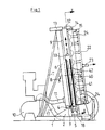
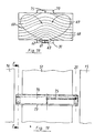
- FIG. 1 and 2 show that the device has a base 1 and thereon a base 2, which carries a horizontally conveying conveyor, which is formed by a sequence of synchronously driven rollers 3.
- a support 4 is arranged between two adjacent rollers 3; the sequence of the supports 4 is arranged on a walking beam 5, which is adjustable up and down, so that the supports 4 between a position in which they protrude above the rollers 3 and a position in which they are below the top of the Rollers 3 are sunk, can be moved back and forth.
- the rollers 3 there is a support wall 6, which is based on the one hand on the base 2 and on the other hand is supported by struts 7 and 8 which are based on the base frame 1 in a position inclined to the rear by approximately 6 ° with respect to the vertical.
- the support wall 6 is designed as an air cushion wall, i.e. it consists of a plate 9 in which a number of bores are distributed, to which compressed air is supplied by a blower 10 via a line 11.
- the rods 12 carry at their front end a holder 14, to which a frame with two walls 15 and 16 is fastened, which run parallel to the support wall 6 and whose distance from the support wall 6 can be changed by actuating the pressure medium cylinders 13.
- the walls 15 and 16 are also designed as air cushion walls and are therefore supplied with compressed air by the fan 10 through a further line 17. Like the support wall 9, they have a number of bores 35 distributed over their surface through which the blower air can escape or be sucked in.
- a further walking beam 18 with a number of supports 19 is arranged below the walls 15 and 16.
- two retractable stops 26 and 27 are arranged, one of which is close to the recess 20 and the other at the outlet end of the wall 16.
- a further position sensor 30 is located at the beginning of the support wall 15.
- a replaceable strip FIG. 7
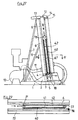
- a height-adjustable suction device 33 is arranged in front of the wall 6, the drive unit of which is not shown in FIG. 2 for reasons of clarity.
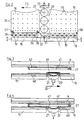
- the nozzle 31 is a flat hollow body 36 in which an elongated nozzle mouth 37 is formed. In the longitudinal direction, the nozzle is divided into three sections 38a, 38b and 38c, which are supplied with gas by separate lines 39a, 39b, 39c.
- the nozzle mouth 37 is framed by seals 44, 45 and 46, namely along the side of two strip-shaped seals 44 and 45, which may consist of foam rubber, for example.
- the seal 45 protrudes further beyond the nozzle opening 37 than the seal 44 and is used for placement on the spacer 41, while the seal 44 is used for placement on the lower edge of the glass plate 40, which lies against the walls 15 and 16 (FIG. 7 ).
- the seal 44 does not run completely straight, but rather approaches with its ends the seal 45, which is shorter than the seal 44.
- the seal 45 At the ends of the seal 45 there are two wedge-shaped seals 46 (see FIG. 8) which, with a sealing surface 46a parallel to the walls 15 and 16, bear against the seal 44 and, moreover, against the inside of the glass plate 40 and which with one oblique sealing surface 46b abuts the spacer 41, which is usually formed on its outside with a corresponding inclined surface.
- the nozzle 31 can also be placed on the lower edge of insulating glass panes of different sizes and thicknesses such that the gap-shaped opening for supplying the gas is sealed sufficiently tightly.
- the gap-shaped opening for glass plates of different thicknesses and different sizes has approximately the same size.
- the suction device 33 opposite the nozzle 31 also has the shape of a nozzle with an elongated mouth 47, which is also framed by seals 48, 49 and 50, of which the longitudinal seal 49 closest to the walls 15, 16 lies against the upper edge of the glass plate 40 is determined, while the parallel second longitudinal seal 48 protrudes slightly further than the seal 49 and is intended to rest on the spacer 41 (see FIG. 13).
- the sealing pieces 50 provided at the ends protrude as far as the seal 48.
- the suction device 33 is arranged in the recess 20 between the two walls 15 and 16, in such a way that the nozzle can be moved up and down in front of the suction cups 21. In the illustration in FIG. 11, the suction cups are combined, in deviation from the illustration in FIGS.
- the lower lever 56 of the four-bar linkage is extended on both sides of the bar 51 beyond the joint located on the arms 55 to such an extent that it projects up to the front of the walls 15 and 16. It is also arranged so deep that its underside is below the nozzle mouth 47 as long as the nozzle of the glass plate 40 is not yet seated.
- a channel 60 leads from the nozzle 33 to the suction side of a blower (not shown).
- the device works as follows:
- a glass plate 40 standing on the rollers 3 and leaning against the supporting wall 6 is transported into the device.
- the position and length of the glass plate 40 is sequentially detected by the sensors 30, 28 and 29. If it is a long glass plate, it is stopped at stop 27. If it is a glass plate that is so short that its rear edge would no longer lie in the area of the wall 15 if it were stopped by the stop 27, it is stopped in front of the stop 26. This ensures that the glass plate, when it has come to rest, covers the recess 20 over its entire length.
- the walking beam 3 is moved upwards, thereby lifting the glass plate 40 from the rollers 3.
- the walls 15 and 16 are approached together to the glass plate 40 and the glass plate is sucked in by sucking air through the holes 35 in the walls 15 and 16. If the glass plate 40 is sucked in in this way, it is moved back together with the walls 15 and 16. It now hangs on the walls 15 and 16 and is supported at the bottom by the now raised supports 19.
- the suction cups 21 are now activated: they additionally suck the glass plate 40 in the area of the recess 20.
- suction cups 21 have sucked firmly onto the outer surface of the glass plate 40, they move back a little, preferably by about 2 mm, and thereby cause a deflection of the glass plate 40, which primarily affects the area of the recess 20.
- the supports 4 are lowered and a further glass plate 42 of the same size but covered with a spacer 41 is conveyed up on the rollers 3, positioned congruently with the glass plate 40 and lifted from the rollers 3 by the supports 4.
- the spacer 41 is coated on both sides with an adhesive.
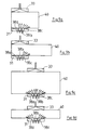
- FIG. 9a An insulating glass pane is filled, which is relatively small in size is. This disc is positioned against the inner stop 26 and filled over the middle and right sections 38b and 38c of the nozzle 31. This method of operation is preferred for insulating glass panes with a length of up to 2 m.
- FIG. 9b shows the filling of a narrower insulating glass pane, the length of which is not more than approximately 2 m and which is therefore also positioned against the inner stop 26 (FIG. 2).
- Such an insulating glass pane can be filled sufficiently quickly and evenly by the right section 38c of the nozzle 31 alone.
- FIG. 9c shows the filling of a large insulating glass pane which is positioned against the outer stop 27 (FIG. 2).
- the nozzle 31 is used in the middle area and the gas is supplied through all three sections 38a, 38b and 38c.
- This method of working is suitable for insulating glass panes that are longer than 2 m and not too low.
- Correspondingly long, but lower insulating glass panes are expediently filled, as shown in FIG. 9d, through the right and left section of the nozzle 31, while the middle section 38b remains closed.
- the nozzle 31 and the suction device 33 are removed from the edge of the insulating glass pane and at the same time the suction cups 21 are depressurized, so that the glass plate 40 suddenly springs against the spacer 41 and the insulating glass pane closes very quickly.
- the pressure medium cylinders 13 By actuating the pressure medium cylinders 13, the walls 15 and 16 are now pressed against the supporting wall 6 and the insulating glass pane is thereby pressed to its desired thickness in a manner known per se.
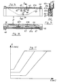
- the device 31 shown in FIGS. 14, 15 and 16 for introducing the gas into the interior of the insulating glass pane differs from the device shown in FIGS. 5 to 8 in that, in addition to a nozzle 61 with a very elongated mouth 61a, it has two further nozzles 62 and 63, which also have elongated orifices 62a and 63a, but are considerably shorter than the nozzle 61, which is the main nozzle. While the main nozzle 61 has a substantially upward outflow direction, the two shorter nozzles 62 and 63 are approximately obliquely to the side in opposite directions, i.e.
- the opening angle of the V should be large, preferably greater than 120 °, in particular approximately 150 °, in order to be able to force a flow even in narrow insulating glass panes of great length and low height , which reaches the two upper corners of the window interior.
- the three nozzles 61, 62 and 63 are arranged in a flat chamber 67 with an elongated mouth, the outline of which corresponds to the device shown in FIG. 6 and is framed in a corresponding manner by seals 44, 45 and 46 with which the device for contacting the lower edge of the insulating glass pane is brought (see Fig. 15).
- the gas is preferably introduced into the interior of the insulating glass pane as follows: through a gap provided at the lower edge of the insulating glass pane, gas, which is heavier than air, is first introduced into the interior of the insulating glass pane through the main nozzle 61 over a wide area, initially with low throughput so that the gas can spread along the lower edge of the insulating glass pane into the two lower corners of the interior. The throughput of the gas is then steadily increased, an upwardly rising front of the heavy gas being formed which displaces the air from the interior through a gap-shaped opening provided at the upper edge of the insulating glass pane.
- a family of lines 68 shows how the front of the gas progresses from bottom to top.
- the main nozzle 61 is closed and instead the V-shaped nozzles 63 and 62 are opened, which - as indicated by the lines 69 - forces a flow reaching the two upper corners of the pane interior , which is deflected in the area of the upper corners and receives a swirl, whereby the air is flushed out of the upper area of the corners.
- the gas is only allowed to flow out of the V-shaped nozzles 62 and 63 for a short time and then the main nozzle is opened again 61, in order to displace the air which has been flushed out of the region of the two upper corners by the action of the V-shaped nozzles 62 and 63 by the upward flow emanating from it.
- insulating glass panes can be very quickly and with little Fill the residual content of air with a gas other than air.
- FIG. 17 shows how the filling process with the main nozzle 61 can expediently be carried out: one begins with a low gas throughput, which should be maintained and the longer the longer the insulating glass pane to be filled, so that the heavy gas runs along the lower pane edge can flow to the two lower corners of the pane interior, before the throughput is then increased to a maximum value, which, however, is chosen so low that turbulence in the pane interior is largely avoided. Accordingly, the right curve in FIG. 17 applies to longer, the left curve for shorter insulating glass panes.
- FIGS. 19 to 21 show a cover element for partially covering the gap formed at the upper edge of the insulating glass pane during the filling process.
- This cover element 70 can advantageously be used instead of the suction nozzle shown in FIGS. 10 to 13 and, like this, is fastened to a carriage 58 which can be moved up and down.
- the cover element 70 is a plate which is arranged essentially vertically in front of the suction bar 51 between the walls 15 and 16 and is mounted on the carriage 58 so as to be pivotable about a horizontal axis 71.
- the cover element 70 is provided in its upper region on the rear with a seal 72 and on its lower edge with a seal 73 which, when the slide 58 is lowered, strikes the spacer 41 of the insulating glass pane and thereby raises the cover element 70 until it is in contact with it Upper seal 72 comes to rest on the suction bar 51. Air emerging from the gap 74 can therefore not flow upward unhindered, but is deflected to the side and must flow to the right and left edge of the cover element 70 before it is released. This obstruction of the air outlet favorably favors the formation of a cross flow in the interior of the pane.
- a narrow line 75 is integrated into the cover element 70, through which a small part of the air or air / gas mixture emerging from the gap 74 can be sucked off and fed to a sensor which measures the oxygen content and thus enables a statement as to how large the residual air content in the disc is still.
- the device shown in FIGS. 22 and 23 corresponds in numerous elements to the device shown in FIGS. 3 to 4, so that in this respect reference can be made to the description there.
- the device shown in FIGS. 22 and 23 differs from the device shown in FIGS. 1 to 4 in that no glass plate is bent in it. Accordingly, the suction cups 21 are missing and instead of two walls 15 and 16 separated by a gap 20, the support wall 6 is only opposite a wall 15 which is designed as an air cushion wall and which is about an axis 76 which, in the plan view according to FIG. 23, at the right end of the wall 15 is arranged and extends parallel to the front of the wall 15 in a vertical plane, is pivotable by a small angle. In addition, the wall 15 can be moved parallel to the support wall 6 as described with reference to FIG. 1.
- the device works as follows:
- a glass plate 40 is conveyed up on the rollers 3, positioned against the stop 27, sucked in by the air cushion wall 15 and lifted from the support wall 6 by parallel displacement of the air cushion wall 15.
- a further glass plate 42 covered with a spacer 41 is conveyed up on the rollers 3 and positioned against the stop 27.
- the air cushion wall 15 is pivoted about the axis 76 by a small angle, so that there is an acute angle between the support wall 6 and the wall 15. Then the wall 15 is approximated by parallel displacement of the support wall 6 until the glass plate 40 reaches the right leg of the spacer 41 in the plan view according to FIG. 23.
- the upper and lower wedge-shaped gaps can be covered, for example by a strip covered with foam rubber or by a high-strength, flexible, inflatable tube 77 or 78, which are displaceable.
- the gap on the left edge of the insulating glass pane is covered in the lower region by a device 31 for supplying the gas, which is introduced at the bottom into the interior of the insulating glass pane and displaces the air from an above, uncovered section of the opening gap.
- a device 31 for supplying the gas which is introduced at the bottom into the interior of the insulating glass pane and displaces the air from an above, uncovered section of the opening gap.
Landscapes
- Engineering & Computer Science (AREA)
- Civil Engineering (AREA)
- Structural Engineering (AREA)
- Securing Of Glass Panes Or The Like (AREA)
- Joining Of Glass To Other Materials (AREA)
Abstract
Claims (37)
- Procédé destiné au montage de vitres isolantes dont on remplit l'espace interne ménagé entre des paires de pans de verre (40, 42) à l'aide d'un gaz dense, les pans de verre étant maintenus à l'écart l'un de l'autre le long de leurs bords à l'intervention d'un écarteur en forme de châssis et étant collés l'un à l'autre, par lequel- on relie l'écarteur (41), des deux côtés, aux deux pans de verre (40, 42) constituant une paire, d'abord seulement sur une partie de leur longueur, de telle sorte que l'on obtienne au moins un accès à l'espace interne ménagé entre les pans de verre (40, 42), entre l'écarteur (41) et au moins un des pans de verre (40, 42),- on introduit le gaz dans l'espace interne à travers un tel accès tandis que les pans de verre (40, 42) sont dressés ou sont disposés en étant essentiellement dressés, et- on ferme chacun de ces accès en reliant, des deux côtés, la longueur restante de l'écarteur (41) aux deux pans de verre (40, 42),dans lequel, au cours de l'introduction du gaz, on empêche l'évacuation de ce dernier hors de l'espace interne ménagé entre les vitres isolantes.
- Procédé destiné au montage de vitres isolantes dont on remplit l'espace interne ménagé entre des paires de pans de verre (40, 42) à l'aide d'un gaz dense, les pans de verre étant maintenus à l'écart l'un de l'autre le long de leurs bords à l'intervention d'un écarteur en forme de châssis et étant collés l'un à l'autre, par lequel- on relie l'écarteur (41), des deux côtés, aux deux pans de verre (40, 42) constituant une paire, d'abord seulement sur une partie de leur longueur, de telle sorte que l'on obtienne au moins un accès à l'espace interne ménagé entre les pans de verre (40, 42), entre l'écarteur (41) et au moins un des pans de verre (40, 42),- on introduit le gaz dans l'espace interne à travers un tel accès tandis que les pans de verre (40, 42) sont dressés ou sont disposés en étant essentiellement dressés, et- on ferme chacun de ces accès en reliant, des deux côtés, la longueur restante de l'écarteur (41) aux deux pans de verre (40, 42),qui englobe la séquence d'étapes ci-après consistant à:- amener l'écarteur (41) contre un des pans de verre (désigné ci-après par l'expression "premier pan de verre" 42),- fléchir élastiquement au moins un des pans de verre dans une zone qui englobe au moins une section de bord du pan de verre (40),- amener l'écarteur (41) contre l'autre pan de verre (désigné ci-après par l'expression "second pan de verre" 40), au moins un accès à l'espace interne régnant entre les pans de verre (40, 42) restant ouvert du fait du fléchissement maintenu,- introduire le gaz dans l'espace interne, à travers un accès ainsi formé, et- fermer chacun de ces accès en supprimant le fléchissement élastique.
- Procédé destiné au montage de vitres isolantes dont on remplit l'espace interne ménagé entre des paires de pans de verre (40, 42) à l'aide d'un gaz dense, les pans de verre étant maintenus à l'écart l'un de l'autre le long de leurs bords à l'intervention d'un écarteur en forme de châssis et étant collés l'un à l'autre, par lequel- on relie l'écarteur (41), des deux côtés, aux deux pans de verre (40, 42) constituant une paire, d'abord seulement sur une partie de leur longueur, de telle sorte que l'on obtienne au moins un accès à l'espace interne ménagé entre les pans de verre (40, 42), entre l'écarteur (41) et au moins un des pans de verre (40, 42),- on introduit le gaz dans l'espace interne à travers un tel accès tandis que les pans de verre (40, 42) sont dressés ou sont disposés en étant essentiellement dressés, et- on ferme chacun de ces accès en reliant, des deux côtés, la longueur restante de l'écarteur (41) aux deux pans de verre (40, 42),qui englobe la séquence d'étapes ci-après consistant à:- amener l'écarteur (41) contre un des pans de verre (désigné ci-après par l'expression "premier" pan de verre 42) et ensuite contre l'autre pan de verre (désigné ci-après par l'expression "second" pan de verre 40),- créer au moins un accès à l'espace interne régnant entre les pans de verre (40, 42) en fléchissant élastiquement au moins un des pans de verre dans une zone qui englobe au moins une section de bord du pan de verre (40),- introduire le gaz dans l'espace interne à travers un accès ainsi créé, et- fermer chacun de ces accès en supprimant le fléchissement élastique.
- Procédé selon la revendication 2 ou 3, caractérisé en qu'on fléchit seulement un des deux pans de verre (40, 42).
- Procédé selon les revendications 2 et 4, caractérisé en qu'on fléchit uniquement le second pan de verre (40).
- Procédé selon la revendication 5, caractérisé en qu'on fléchit le second pan de verre (40) avant de le relier à l'écarteur (41).
- Procédé selon l'une quelconque des revendications précédentes, caractérisé en qu'on étanche au moins partiellement les accès à l'espace interne ménagé entre les deux pans de verre (40, 42) aux bords des pans de verre (40, 42) lorsqu'on procède à l'introduction du gaz.
- Procédé selon la revendication 1, destiné au montage de vitres isolantes rectangulaires, caractérisé en ce qu'on relie l'écarteur (41) à un pan de verre (42) le long de l'ensemble de ses quatre bords et à l'autre pan de verre (40) qui forme un très petit angle avec le premier pan de verre (42), d'abord uniquement le long d'un de ses quatre bords et en ce qu'on fait pivoter l'un vers l'autre les deux pans de verre (40, 42) après avoir introduit le gaz, dans le but de fermer l'espace interne.
- Procédé destiné au montage de vitres isolantes rectangulaires selon l'une quelconque des revendications 1 à 7, caractérisé en ce qu'on fléchit chaque pan de verre (40) en deux coins.
- Procédé destiné au montage de vitres isolantes rectangulaires selon l'une quelconque des revendications 1 à 7, caractérisé en ce qu'on fléchit chaque pan de verre (40) sur deux sections de bord opposées l'une à l'autre.
- Procédé selon la revendication 10, caractérisé en qu'on fléchit chaque pan de verre (40) parallèlement à un de ses bords.
- Procédé selon l'une quelconque des revendications 1 à 7 ou 10 ou encore 11, caractérisé en qu'on fléchit chaque pan de verre (40) de telle sorte que sa surface externe soit convexe.
- Procédé selon la revendication 12, caractérisé en qu'on fléchit chaque pan de verre (40) dans une zone partielle en forme de bande, qui s'étend à l'écart de ses coins depuis une section de bord jusqu'à la section de bord opposée du pan de verre (40).
- Procédé selon l'une quelconque des revendications 1 à 7 ou 9 ou encore 13, caractérisé en qu'on fléchit chaque pan de verre (40) en l'aspirant dans une ou plusieurs zones partielles de sa surface externe, des forces opposées à la force d'aspiration s'exerçant simultanément sur sa surface externe à l'écart de ces zones partielles.
- Procédé selon la revendication 14, caractérisé en qu'on aspire chaque pan de verre (40) dans une zone partielle en forme de bande de sa surface externe, cette zone s'étendant - de préférence de manière rectiligne - depuis une section de bord jusqu'à la section de bord opposée du pan de verre (40).
- Procédé selon les revendications 11 et 15, caractérisé en qu'on exerce les forces opposées à la force d'aspiration en dehors d'une bande d'environ 30 cm de large, sur la surface externe de chaque pan de verre (40) destiné à être fléchi, et en ce que cette bande se trouve sur un des bords du pan de verre.
- Procédé selon l'une quelconque des revendications précédentes, caractérisé en qu'on introduit le gaz à partir du bas, l'air étant chassé vers le haut.
- Dispositif destiné au montage de vitres isolantes dont on remplit l'espace interne ménagé entre des paires de pans de verre (40, 42) à l'aide d'un gaz dense, les pans de verre étant disposés en étant dressés ou en étant essentiellement dressés et étant maintenus à l'écart l'un de l'autre le long de leurs bords à l'intervention d'un écarteur en forme de châssis et étant collés l'un à l'autre, ce dispositif comprenant un transporteur (3) destiné à transporter les pans de verre (40, 42) à l'horizontale, un mécanisme d'appui (6) sur lequel viennent s'appuyer les pans de verre (40, 42) acheminés sur le transporteur (3),un support (15, 16, 35) à écartement variable par rapport au mécanisme d'appui (6) tout en étant parallèle à ce dernier, destiné à maintenir un pan de verre (40) à l'écart de l'autre pan de verre (42), dans lequel des moyens déterminés de positionnement définissent, contre le support (15, 16, 35), une surface de positionnement destinée au pan de verre (40), pour que vienne s'y appuyer la face externe d'un pan de verre (40) (cette surface étant désignée ci-après comme étant la "face antérieure" du support (15, 16, 35),ainsi que des moyens (12, 13, 14) destinés à modifier l'écartement entre le support (15, 16, 35) et le mécanisme d'appui (6),dans lequel le support (15) et le mécanisme d'appui (6) peuvent pivoter l'un par rapport à l'autre entre une première position terminale dans laquelle ils sont disposés parallèlement l'un à l'autre et une seconde position terminale dans laquelle ils forment mutuellement un angle aigu,un mécanisme (31) étant prévu pour acheminer le gaz dans la zone ménagée entre le support (15) et le mécanisme d'appui (6), caractérisé en ce qu'on prévoit des éléments de recouvrement destinés à recouvrir les accès à l'espace interne ménagé entre les deux pans de verre (40, 42), sur les bords de ces derniers.
- Dispositif destiné au montage de vitres isolantes dont on remplit l'espace interne ménagé entre des paires de pans de verre (40, 42) à l'aide d'un gaz dense, les pans de verre étant disposés en étant dressés ou en étant essentiellement dressés et étant maintenus à l'écart l'un de l'autre le long de leurs bords à l'intervention d'un écarteur (41) en forme de châssis et étant collés l'un à l'autre, ce dispositif comprenantun transporteur (3) destiné à transporter les pans de verre (40, 42) à l'horizontale, un mécanisme d'appui (6) sur lequel viennent s'appuyer les pans de verre (40, 42) acheminés sur le transporteur (3), etun support (15, 16, 35) à écartement variable par rapport au mécanisme d'appui (6) tout en étant parallèle à ce dernier, destiné à maintenir un pan de verre (40) à l'écart de l'autre pan de verre (42), dans lequel des moyens déterminés de positionnement définissent, contre le support (15, 16, 35), une surface de positionnement destinée au pan de verre (40), pour que vienne s'y appuyer la face externe d'un pan de verre (40) (cette surface étant désignée ci-après comme étant la "face antérieure" du support (15, 16, 35),ainsi que des moyens (12, 13, 14) destinés à modifier l'écartement entre le support (15, 16, 35) et le mécanisme d'appui (6),caractérisé en ce qu'au support (15, 16, 35) est attribué au moins un mécanisme d'aspiration (21) dirigé vers le mécanisme d'appui (6), qui peut coulisser vers l'avant jusque contre la face antérieure de ce dernier et qui peut coulisser en retour derrière cette face antérieure,et en ce qu'on prévoit un mécanisme (31) pour acheminer le gaz.
- Dispositif selon la revendication 18 ou 19, caractérisé en ce que le support (15, 16, 35) consiste en une paroi (15, 16) munie de moyens de retenue (35) destinés à maintenir un pan de verre (40), eten ce qu'un évidement est pratiqué dans la paroi (15, 16) ou encore en ce que la paroi (15, 16) est subdivisée en deux sections (15 et 16) par un évidement (20) et en ce que le mécanisme d'aspiration (21) ou plusieurs de ces derniers sont disposés dans l'évidement (20).
- Dispositif selon la revendication 18, 19 ou 20, caractérisé en ce que, pour le travail avec des pans de verre (40, 42) posés sur chant, le mécanisme d'appui (6) s'étend au-dessus du transporteur (3) et est un peu incliné vers l'arrière pour que les pans de verre (40, 42) disposés sur le transporteur (3) puissent venir s'y appuyer,
et en ce que le mécanisme (31) destiné à acheminer le gaz est disposé à hauteur du transporteur (3) ou au-dessus du transporteur (3) avec un écartement variable par rapport à ce dernier. - Dispositif selon la revendication 18, 19 ou 20, caractérisé en ce que les moyens de retenue de la paroi (15, 16) sont des mécanismes d'aspiration (10, 35).
- Dispositif selon la revendication 18, 19 ou 20, caractérisé en ce que le mécanisme (31) destiné à acheminer le gaz est disposé en face d'un mécanisme d'aspiration (33) avec un écartement variable par rapport à ce dernier.
- Dispositif selon la revendication 20, caractérisé en ce que, dans l'évidement (20) pratiqué dans la paroi (15, 16), sont disposés une série de plusieurs mécanismes d'aspiration (21).
- Dispositif selon la revendication 24, caractérisé en qu'on peut activer les mécanismes d'aspiration (21) individuellement ou par groupes.
- Dispositif selon les revendications 18 à 25, caractérisé en ce que le mécanisme d'appui (6) est une paroi à coussin d'air, à travers les ouvertures (35) de laquelle on peut, à volonté, souffler ou aspirer de l'air.
- Dispositif selon la revendication 18 ou 19, caractérisé en ce que le mécanisme (31) destiné à acheminer le gaz, est muni d'éléments de guidage (32) destinés à répartir le courant de gaz dans différentes directions.
- Dispositif selon la revendication 18, 19 ou 27, caractérisé en ce que le mécanisme (31) destiné à acheminer le gaz, présente un orifice (37) s'étirant en longueur et destiné à venir s'appliquer contre le bord des pans de verre (40, 42) ou bien contre le bord d'un pan de verre (40) et contre l'écarteur (41).
- Dispositif selon la revendication 23, caractérisé en ce que le mécanisme d'aspiration (33) présente un orifice (47) étiré en longueur et destiné à venir s'appliquer contre le bord des pans de verre (40, 42) ou bien contre le bord d'un pan de verre (40) et contre l'écarteur (41).
- Dispositif selon les revendications 27 et 28, caractérisé en que l'orifice (37) du mécanisme (31) destiné à acheminer le gaz est subdivisé en plusieurs sections (de préférence trois) (38a, 38b, 38c) dans lesquelles les éléments de guidage (32) sont différemment orientés et qui peuvent être alimentées par le gaz de manière séparée comme on le souhaite, au moyen de canalisations séparées (39a, 39b, 39c).
- Dispositif selon la revendication 25 ou 29, caractérisé en ce que l'orifice (47) du mécanisme (31, 33) destiné à acheminer ou à aspirer le gaz est entouré d'un ou de plusieurs joints étanches (44, 45, 46 ; 48, 49, 50).
- Dispositif selon la revendication 19, caractérisé en ce que les dispositifs d'aspiration (21) peuvent se rétracter sur environ 2 mm derrière la face antérieure du support (15, 16).
- Dispositif selon la revendication 18, 19 ou 20, caractérisé en que, pour empêcher l'évacuation du gaz hors de l'espace interne ménagé entre les pans de verre (40, 42), face au mécanisme (31) destiné à acheminer le gaz, est disposé un élément de recouvrement (70) à écartement variable.
- Procédé selon la revendication 17, caractérisé en ce qu'on introduit le gaz par le bord inférieur des pans de verre (40, 42) au sein de l'espace interne et, en fait, d'abord avec un courant dirigé essentiellement vers le montant supérieur de l'écarteur (41), ensuite à un moment plus tardif et pendant un bref moment, avec un courant dirigé en biais vers le haut vers les deux montants de l'écarteur (41) faisant saillie, et ensuite, encore une fois, avec un courant dirigé vers le montant supérieur de l'écarteur (41) et en ce que l'air est chassé par une fente (74) pratiquée dans le bord supérieur, la fente se trouvant, de préférence, au-dessus de l'accès formé au bord inférieur.
- Procédé selon la revendication 34, caractérisé en ce qu'on choisit comme moment plus tardif, n'importe quel moment auquel on constate une évacuation du gaz introduit par le bas, au bord supérieur des pans de verre (40, 42).
- Procédé selon l'une quelconque des revendications 1 à 17 ou encore 34 et 35, caractérisé en qu'on augmente la quantité de gaz introduit au cours du processus de remplissage, par unité de temps.
- Procédé selon l'une quelconque des revendications 2 à 17 ou 34 à 36, caractérisé en qu'on empêche l'évacuation du gaz hors de l'espace interne.
Priority Applications (1)
| Application Number | Priority Date | Filing Date | Title |
|---|---|---|---|
| AT89905079T ATE68238T1 (de) | 1988-05-04 | 1989-05-04 | Verfahren und vorrichtung zum fuellen von isolierglasscheiben mit einem schwergas. |
Applications Claiming Priority (5)
| Application Number | Priority Date | Filing Date | Title |
|---|---|---|---|
| DE3815139 | 1988-05-04 | ||
| DE3815139 | 1988-05-04 | ||
| DE3832836 | 1988-09-28 | ||
| DE3832836 | 1988-09-28 | ||
| PCT/EP1989/000493 WO1989011021A1 (fr) | 1988-05-04 | 1989-05-04 | Procede et dispositif pour remplir des vitres isolantes de gaz lourd |
Publications (3)
| Publication Number | Publication Date |
|---|---|
| EP0406325A1 EP0406325A1 (fr) | 1991-01-09 |
| EP0406325B1 EP0406325B1 (fr) | 1991-10-09 |
| EP0406325B2 true EP0406325B2 (fr) | 1997-07-16 |
Family
ID=25867731
Family Applications (1)
| Application Number | Title | Priority Date | Filing Date |
|---|---|---|---|
| EP89905079A Expired - Lifetime EP0406325B2 (fr) | 1988-05-04 | 1989-05-04 | Procede et dispositif pour remplir des vitres isolantes de gaz lourd |
Country Status (4)
| Country | Link |
|---|---|
| US (2) | US5366574A (fr) |
| EP (1) | EP0406325B2 (fr) |
| DE (1) | DE58900360D1 (fr) |
| WO (1) | WO1989011021A1 (fr) |
Families Citing this family (48)
| Publication number | Priority date | Publication date | Assignee | Title |
|---|---|---|---|---|
| DE4100697C3 (de) * | 1990-02-28 | 1999-07-15 | Peter Lisec | Verfahren und Vorrichtung zum Füllen des Innenraumes von Isolierglasscheibenrohlingen mit Gas |
| AT408982B (de) * | 1990-02-28 | 2002-04-25 | Lisec Peter | Verfahren zum füllen des innenraumes von isolierglasscheiben mit gas |
| DE4022185A1 (de) * | 1990-07-13 | 1992-01-16 | Lenhardt Maschinenbau | Verfahren und vorrichtung zum zusammenbauen von isolierglasscheiben, die mit einem von luft verschiedenen gas gefuellt sind |
| GB9022917D0 (en) * | 1990-10-22 | 1990-12-05 | Willian Design Ltd | Apparatus for turning a sheet-like workpiece |
| EP0498787A3 (en) * | 1991-02-04 | 1992-10-14 | Peter Lisec | Method and device for manufacturing insulating glazing units |
| DE4231424C2 (de) * | 1992-09-19 | 1998-04-09 | Lenhardt Maschinenbau | Verfahren und Vorrichtung zum Zusammenbauen von Isolierglasscheiben, deren Glastafeln durch einen plastischen Abstandhalter auf Abstand gehalten und miteinander verklebt sind |
| DE9302744U1 (de) * | 1992-12-18 | 1994-05-19 | Lisec, Peter, Amstetten-Hausmening | Vorrichtung zum Füllen von Isolierglasscheiben mit einem von Luft unterschiedlichen Gas |
| DE4335673C1 (de) * | 1993-10-20 | 1995-05-11 | Lenhardt Maschinenbau | Verfahren und Vorrichtung zum Zusammenbauen von Isolierglasscheiben mit rahmenförmigen Abstandhaltern aus einer plastischen Masse |
| DE4335671A1 (de) * | 1993-10-20 | 1995-05-04 | Lenhardt Maschinenbau | Verfahren und Vorrichtung zum Zusammenbauen von Isolierglasscheiben mit rahmenförmigen Abstandhaltern aus einer plastischen Masse |
| ATE166420T1 (de) * | 1994-03-24 | 1998-06-15 | Peter Lisec | Verfahren zum zusammenbauen von isolierglasscheiben, deren innenraum mit einem schwergas gefüllt ist und vorrichtung zum füllen von isolierglasscheiben mit schwergas |
| DE9408902U1 (de) * | 1994-05-31 | 1995-09-28 | DCL Glas Consult GmbH, 82054 Sauerlach | Vorrichtung zum Befüllen eines Zwischenraumes einer Isolierglaseinheit |
| US5805330A (en) * | 1996-03-15 | 1998-09-08 | Gentex Corporation | Electro-optic window incorporating a discrete photovoltaic device |
| US6433913B1 (en) | 1996-03-15 | 2002-08-13 | Gentex Corporation | Electro-optic device incorporating a discrete photovoltaic device and method and apparatus for making same |
| DE19617198A1 (de) * | 1996-04-29 | 1997-11-13 | Lenhardt Maschinenbau | Verfahren zum Herstellen von Isolierglasscheiben mit thermoplastischem Abstandhalter |
| US5948195A (en) * | 1997-03-11 | 1999-09-07 | Artic Window, Inc. | Process for rapid manufacturing multi-pane glass windows |
| US6216751B1 (en) * | 1997-10-24 | 2001-04-17 | Cardinal Ig Company | Method of reliably detecting seal failures |
| US5957169A (en) * | 1997-10-24 | 1999-09-28 | Cardinal Ig Company | Apparatus and method for filling insulated glass units with insulating gas |
| DE19851569C2 (de) * | 1998-11-09 | 2003-01-30 | Armin Schwab | Sensor zur Zustandsüberprüfung der Gasfüllung im Isolierraum einer Isolierglasscheibe und Isolierglasscheibe |
| US6336984B1 (en) | 1999-09-24 | 2002-01-08 | Guardian Industries Corporation | Vacuum IG window unit with peripheral seal at least partially diffused at temper |
| US6365242B1 (en) | 1999-07-07 | 2002-04-02 | Guardian Industries Corp. | Peripheral seal for vacuum IG window unit |
| US6558494B1 (en) | 1999-09-24 | 2003-05-06 | Guardian Industries Corp. | Vacuum IG window unit with edge seal at least partially diffused at temper and completed via microwave curing, and corresponding method of making the same |
| US6701749B2 (en) | 2000-09-27 | 2004-03-09 | Guardian Industries Corp. | Vacuum IG window unit with edge seal at least partially diffused at temper and completed via microwave curing, and corresponding method of making the same |
| DE10050676C2 (de) | 2000-10-05 | 2002-08-01 | Lenhardt Maschinenbau | Verfahren zum Zusammenbauen und Verpressen von Isolierglasscheiben mit einem plastischen Abstandhalter |
| US6916392B2 (en) | 2001-06-21 | 2005-07-12 | Cardinal Ig Company | Producing and servicing insulating glass units |
| DE10138346C2 (de) * | 2001-08-03 | 2003-12-04 | Lenhardt Maschinenbau | Vorrichtung zum Zusammenbauen von Isolierglasscheiben |
| US6606837B2 (en) * | 2001-08-28 | 2003-08-19 | Cardinal Ig | Methods and devices for simultaneous application of end sealant and sash sealant |
| US6804924B2 (en) * | 2001-10-12 | 2004-10-19 | Cardinal Ig Company | Repair of insulating glass units |
| US6793971B2 (en) * | 2001-12-03 | 2004-09-21 | Cardinal Ig Company | Methods and devices for manufacturing insulating glass units |
| US7184146B2 (en) * | 2003-06-24 | 2007-02-27 | Cardinal Ig Company | Methods and apparatus for evaluating insulating glass units |
| DE102004009858B4 (de) * | 2004-02-25 | 2006-05-04 | Karl Lenhardt | Verfahren zum Positionieren von Glastafeln in einer vertikalen Zusammenbau- und Pressvorrichtung für Isolierglasscheiben |
| DE102006018333A1 (de) * | 2006-04-19 | 2007-10-25 | Karl Lenhardt | Vorrichtung zum Zusammenbauen von Insolierglasscheiben, die mit einem von Luft verschiedenen Gas gefüllt sind |
| WO2009020615A1 (fr) * | 2007-08-07 | 2009-02-12 | Hunter Douglas Inc. | Panneau de verre isolé translucide |
| ITTV20080031A1 (it) | 2008-02-20 | 2009-08-21 | For El Base Di Vianello Fortunato & C Snc | Dispositivo automatico e procedimento automatico per il riempimento del vetro isolante composto da almeno due lastre di vetro ed almeno un telaio distanziatore con gas diverso dall'aria. |
| US8235076B2 (en) * | 2009-02-02 | 2012-08-07 | American Air Liquide, Inc. | Method and system for optimized filling of an enclosure |
| US20100243148A1 (en) * | 2009-03-27 | 2010-09-30 | Stefan Kaufmann | Apparatus and method for laminating solar modules |
| US8316596B2 (en) * | 2009-09-15 | 2012-11-27 | Pella Corporation | IG unit membrane valve and pressure modification |
| US8381382B2 (en) * | 2009-12-31 | 2013-02-26 | Cardinal Ig Company | Methods and equipment for assembling triple-pane insulating glass units |
| DE102010035748B4 (de) * | 2010-04-29 | 2013-01-03 | Bystronic Lenhardt Gmbh | Verfahren zum Zusammenbauen von Isolierglasscheiben, die drei zueinander parallele Glasplatten haben |
| US8627856B2 (en) | 2010-06-28 | 2014-01-14 | Integrated Automation Systems, Llc | Continuous gas filling process and apparatus for fabrication of insulating glass units |
| FR2984300B1 (fr) * | 2011-12-15 | 2014-11-21 | Saint Gobain | Procede de fabrication d'un vitrage multiple rempli de gaz |
| US10012019B2 (en) | 2013-12-31 | 2018-07-03 | Guardian Glass, LLC | Vacuum insulating glass (VIG) unit with metallic peripheral edge seal and/or methods of making the same |
| US9784027B2 (en) | 2013-12-31 | 2017-10-10 | Guardian Glass, LLC | Vacuum insulating glass (VIG) unit with metallic peripheral edge seal and/or methods of making the same |
| US10280680B2 (en) | 2013-12-31 | 2019-05-07 | Guardian Glass, LLC | Vacuum insulating glass (VIG) unit with pump-out port sealed using metal solder seal, and/or method of making the same |
| US10113354B2 (en) | 2013-12-31 | 2018-10-30 | Cardinal Ig Company | Multiple-pane insulating glazing unit assembly, gas filling, and pressing machine |
| US9862126B2 (en) | 2014-03-19 | 2018-01-09 | Great Dane Llc | Method and apparatus for forming objects having a core and an outer surface structure |
| US10145005B2 (en) | 2015-08-19 | 2018-12-04 | Guardian Glass, LLC | Techniques for low temperature direct graphene growth on glass |
| US10968685B2 (en) * | 2016-01-04 | 2021-04-06 | PDS IG Holding LLC | Gas filling of an insulating glass unit |
| US11187028B2 (en) | 2017-07-01 | 2021-11-30 | PDSD IG Holding LLC | Filling and sealing device and method for an insulated glass unit |
Family Cites Families (16)
| Publication number | Priority date | Publication date | Assignee | Title |
|---|---|---|---|---|
| US2756467A (en) * | 1952-11-05 | 1956-07-31 | Etling Birtus Oliver | Multiple-pane glazing unit and manufacture thereof |
| US3078627A (en) * | 1960-11-15 | 1963-02-26 | Libbey Owens Ford Glass Co | Method and apparatus for fabricating all-glass multiple sheet glazing units |
| US3683974A (en) * | 1970-10-08 | 1972-08-15 | Ppg Industries Inc | Method for purging and filling multiple glazed units |
| FI53117C (fr) * | 1971-06-18 | 1978-02-10 | Glaverbel | |
| DE2905841C2 (de) * | 1979-02-15 | 1984-04-19 | Josef Käuferle KG Stahlbau, 8890 Aichach | Verfahren und Anlage zur Herstellung einer Verbundplatte |
| DE3101342C2 (de) * | 1981-01-17 | 1984-08-02 | Vereinigte Glaswerke Gmbh, 5100 Aachen | "Verfahren zur Herstellung von gasgefüllten Isolierglaseinheiten und Vorrichtung zur Durchführung des Verfahrens" |
| AT385499B (de) * | 1981-05-11 | 1988-04-11 | Lisec Peter | Vorrichtung zum pressen von isolierglas |
| AT368985B (de) * | 1981-05-26 | 1982-11-25 | Lisec Peter | Vorrichtung zum fuellen von isolierglas mit schwergas |
| DE3310441C1 (de) * | 1983-03-23 | 1984-09-06 | Flachglas AG, 8510 Fürth | Anlage fuer die Randversiegelung von Isolierglaseinheiten |
| DE3402323A1 (de) * | 1984-01-24 | 1985-08-01 | Interpane Entwicklungs- und Beratungsgesellschaft mbH & Co. KG, 3471 Lauenförde | Verfahren zum herstellen eines wenigstens aus zwei scheiben bestehenden isolierglases |
| AT393827B (de) * | 1987-01-15 | 1991-12-27 | Lisec Peter | Verfahren und vorrichtung zum fuellen einer isolierglaseinheit mit fuellgas |
| US4773453A (en) * | 1987-04-14 | 1988-09-27 | Dcl Glas-Consult Gmbh | Procedure for filling insulating glass units |
| AT393830B (de) * | 1988-01-11 | 1991-12-27 | Lisec Peter | Vorrichtung zum fuellen von isolierglas mit sondergas |
| AT408982B (de) * | 1990-02-28 | 2002-04-25 | Lisec Peter | Verfahren zum füllen des innenraumes von isolierglasscheiben mit gas |
| DE4022185A1 (de) * | 1990-07-13 | 1992-01-16 | Lenhardt Maschinenbau | Verfahren und vorrichtung zum zusammenbauen von isolierglasscheiben, die mit einem von luft verschiedenen gas gefuellt sind |
| DE9302744U1 (de) * | 1992-12-18 | 1994-05-19 | Lisec, Peter, Amstetten-Hausmening | Vorrichtung zum Füllen von Isolierglasscheiben mit einem von Luft unterschiedlichen Gas |
-
1989
- 1989-05-04 DE DE8989905079T patent/DE58900360D1/de not_active Expired - Fee Related
- 1989-05-04 EP EP89905079A patent/EP0406325B2/fr not_active Expired - Lifetime
- 1989-05-04 US US07/613,504 patent/US5366574A/en not_active Expired - Lifetime
- 1989-05-04 WO PCT/EP1989/000493 patent/WO1989011021A1/fr not_active Ceased
-
1996
- 1996-10-22 US US08/734,841 patent/US5762739A/en not_active Expired - Fee Related
Also Published As
| Publication number | Publication date |
|---|---|
| US5366574A (en) | 1994-11-22 |
| DE58900360D1 (de) | 1991-11-14 |
| EP0406325A1 (fr) | 1991-01-09 |
| WO1989011021A1 (fr) | 1989-11-16 |
| EP0406325B1 (fr) | 1991-10-09 |
| US5762739A (en) | 1998-06-09 |
Similar Documents
| Publication | Publication Date | Title |
|---|---|---|
| EP0406325B2 (fr) | Procede et dispositif pour remplir des vitres isolantes de gaz lourd | |
| DE102010035748B4 (de) | Verfahren zum Zusammenbauen von Isolierglasscheiben, die drei zueinander parallele Glasplatten haben | |
| EP0539407B1 (fr) | Procede et dispositif d'assemblage de vitres isolantes remplies d'un gaz autre que l'air | |
| DE102009048642B4 (de) | Vorrichtung zum Zusammenbauen eines Fensterflügels mit integrierter Isolierglasscheibe | |
| CH659506A5 (de) | Vorrichtung zum ansetzen von abstandhalterrahmen. | |
| DE8715749U1 (de) | Vorrichtung zum Füllen einer Isolierglaseinheit mit Füllgas | |
| DE3101342A1 (de) | "verfahren zur herstellung von gasgefuellten isolierglaseinheiten und vorrichtung zur durchfuehrung des verfahrens" | |
| DE9105850U1 (de) | Vorrichtung zum Brechen von Glasscheiben | |
| DE29504900U1 (de) | Vorrichtung zum Zusammenbauen von Isolierglasscheiben, deren Innenraum mit einem Schwergas gefüllt ist | |
| DE4307403A1 (de) | Verfahren und Vorrichtung zum Einrichten, Gasfüllen und Verpressen von Einzelscheiben und/oder bereits vorgefertigten Scheibenanordnungen als zwei Komponenten bei der Herstellung von Isolierglasscheiben | |
| EP2483503B1 (fr) | Procédé d'assemblage d'un battant de fenêtre comprenant une vitre isolante intégrée | |
| EP1769130B1 (fr) | Procede et dispositif de montage de vitres isolantes remplies d'un gaz autre que l'air | |
| DE102004009860B4 (de) | Verfahren und Vorrichtung zum Zusammenbauen von Isolierglasscheiben, die mit einem von Luft verschiedenen Gas gefüllt sind | |
| DE3914706A1 (de) | Verfahren und vorrichtung zum zusammenbauen von isolierglasscheiben, die mit einem von luft verschiedenen gas gefuellt sind | |
| DE2712651C2 (de) | Rahmenauflegestation in einer Anlage zum Zusammenbau von Isolierglas | |
| DE4202612A1 (de) | Verfahren und vorrichtung zum herstellen von isolierglasscheiben | |
| EP2007962B1 (fr) | Dispositif pour assembler des vitres de verre isolantes qui sont remplies d'un gaz différent de l'air | |
| DE4315986C2 (de) | Verfahren und Vorrichtung zum Herstellen einer Isolierglaseinheit | |
| DE4419052A1 (de) | Verfahren und Vorrichtung zum Befüllen eines Zwischenraumes einer Isolierglaseinheit | |
| DE8915718U1 (de) | Vorrichtung zum Zusammenbauen von Isolierglasscheiben, die mit einem von Luft verschiedenen Gas gefüllt sind | |
| DE19962034C1 (de) | Einrichtung zum Abdichten einer Randfuge einer noch nicht geschlosenen Isolierglasscheibe an einer Vorrichtung zum Zusammenbauen von Isolierglasscheiben | |
| DE2055252B2 (de) | Verfahren zum Biegen von Glasscheiben und Vorrichtung zur Durchführung des Verfahrens | |
| DE4212256C2 (de) | Vorrichtung zum Zusammenbauen von zwei Isolierglasscheiben die mit einem von Luft verschiedenen Gas gefüllt sind | |
| DE9205069U1 (de) | Vorrichtung zum Zusammenbauen von zwei Isolierglasscheiben die mit einem von Luft verschiedenen Gas gefüllt sind | |
| AT528522B1 (de) | Verfahren und Vorrichtung zum Ansetzen von Abstandhalterrahmen |
Legal Events
| Date | Code | Title | Description |
|---|---|---|---|
| PUAI | Public reference made under article 153(3) epc to a published international application that has entered the european phase |
Free format text: ORIGINAL CODE: 0009012 |
|
| 17P | Request for examination filed |
Effective date: 19901031 |
|
| AK | Designated contracting states |
Kind code of ref document: A1 Designated state(s): AT BE CH DE FR GB IT LI |
|
| 17Q | First examination report despatched |
Effective date: 19910404 |
|
| GRAA | (expected) grant |
Free format text: ORIGINAL CODE: 0009210 |
|
| AK | Designated contracting states |
Kind code of ref document: B1 Designated state(s): AT BE CH DE FR GB IT LI |
|
| REF | Corresponds to: |
Ref document number: 68238 Country of ref document: AT Date of ref document: 19911015 Kind code of ref document: T |
|
| REF | Corresponds to: |
Ref document number: 58900360 Country of ref document: DE Date of ref document: 19911114 |
|
| ET | Fr: translation filed | ||
| ITF | It: translation for a ep patent filed | ||
| GBT | Gb: translation of ep patent filed (gb section 77(6)(a)/1977) | ||
| PLBI | Opposition filed |
Free format text: ORIGINAL CODE: 0009260 |
|
| 26 | Opposition filed |
Opponent name: GLASTECHNISCHE INDUSTRIE PETER LISEC GMBH, Effective date: 19920505 |
|
| PLAW | Interlocutory decision in opposition |
Free format text: ORIGINAL CODE: EPIDOS IDOP |
|
| APAC | Appeal dossier modified |
Free format text: ORIGINAL CODE: EPIDOS NOAPO |
|
| APAC | Appeal dossier modified |
Free format text: ORIGINAL CODE: EPIDOS NOAPO |
|
| PLAW | Interlocutory decision in opposition |
Free format text: ORIGINAL CODE: EPIDOS IDOP |
|
| PUAH | Patent maintained in amended form |
Free format text: ORIGINAL CODE: 0009272 |
|
| STAA | Information on the status of an ep patent application or granted ep patent |
Free format text: STATUS: PATENT MAINTAINED AS AMENDED |
|
| 27A | Patent maintained in amended form |
Effective date: 19970716 |
|
| AK | Designated contracting states |
Kind code of ref document: B2 Designated state(s): AT BE CH DE FR GB IT LI |
|
| REG | Reference to a national code |
Ref country code: CH Ref legal event code: AEN Free format text: AUFRECHTERHALTUNG DES PATENTES IN GEAENDERTER FORM |
|
| ITF | It: translation for a ep patent filed | ||
| GBTA | Gb: translation of amended ep patent filed (gb section 77(6)(b)/1977) | ||
| EN | Fr: translation not filed | ||
| EN | Fr: translation not filed |
Free format text: BO 97/50 PAGES 219 LA MENTION DE LA NON REMISE APRES OPPOSITION DE CETTE TRADUCTION. LA MENTION DE LA NON REMISE APRES OPPOSITION DE CETTE TRADUCTION EST PUBLIEE DANS LE PRESENT BOPI. |
|
| ET3 | Fr: translation filed ** decision concerning opposition | ||
| REG | Reference to a national code |
Ref country code: GB Ref legal event code: IF02 |
|
| PGFP | Annual fee paid to national office [announced via postgrant information from national office to epo] |
Ref country code: GB Payment date: 20030410 Year of fee payment: 15 |
|
| PGFP | Annual fee paid to national office [announced via postgrant information from national office to epo] |
Ref country code: FR Payment date: 20030520 Year of fee payment: 15 |
|
| PGFP | Annual fee paid to national office [announced via postgrant information from national office to epo] |
Ref country code: CH Payment date: 20030523 Year of fee payment: 15 |
|
| PGFP | Annual fee paid to national office [announced via postgrant information from national office to epo] |
Ref country code: DE Payment date: 20040324 Year of fee payment: 16 |
|
| PG25 | Lapsed in a contracting state [announced via postgrant information from national office to epo] |
Ref country code: GB Free format text: LAPSE BECAUSE OF NON-PAYMENT OF DUE FEES Effective date: 20040504 |
|
| PGFP | Annual fee paid to national office [announced via postgrant information from national office to epo] |
Ref country code: AT Payment date: 20040521 Year of fee payment: 16 |
|
| PGFP | Annual fee paid to national office [announced via postgrant information from national office to epo] |
Ref country code: BE Payment date: 20040525 Year of fee payment: 16 |
|
| PG25 | Lapsed in a contracting state [announced via postgrant information from national office to epo] |
Ref country code: LI Free format text: LAPSE BECAUSE OF NON-PAYMENT OF DUE FEES Effective date: 20040531 Ref country code: CH Free format text: LAPSE BECAUSE OF NON-PAYMENT OF DUE FEES Effective date: 20040531 |
|
| GBPC | Gb: european patent ceased through non-payment of renewal fee |
Effective date: 20040504 |
|
| REG | Reference to a national code |
Ref country code: CH Ref legal event code: PL |
|
| PG25 | Lapsed in a contracting state [announced via postgrant information from national office to epo] |
Ref country code: FR Free format text: LAPSE BECAUSE OF NON-PAYMENT OF DUE FEES Effective date: 20050131 |
|
| REG | Reference to a national code |
Ref country code: FR Ref legal event code: ST |
|
| PG25 | Lapsed in a contracting state [announced via postgrant information from national office to epo] |
Ref country code: IT Free format text: LAPSE BECAUSE OF NON-PAYMENT OF DUE FEES;WARNING: LAPSES OF ITALIAN PATENTS WITH EFFECTIVE DATE BEFORE 2007 MAY HAVE OCCURRED AT ANY TIME BEFORE 2007. THE CORRECT EFFECTIVE DATE MAY BE DIFFERENT FROM THE ONE RECORDED. Effective date: 20050504 Ref country code: AT Free format text: LAPSE BECAUSE OF NON-PAYMENT OF DUE FEES Effective date: 20050504 |
|
| PG25 | Lapsed in a contracting state [announced via postgrant information from national office to epo] |
Ref country code: BE Free format text: LAPSE BECAUSE OF NON-PAYMENT OF DUE FEES Effective date: 20050531 |
|
| APAH | Appeal reference modified |
Free format text: ORIGINAL CODE: EPIDOSCREFNO |
|
| BERE | Be: lapsed |
Owner name: *LENHARDT MASCHINENBAU G.M.B.H. Effective date: 20050531 |
|
| PG25 | Lapsed in a contracting state [announced via postgrant information from national office to epo] |
Ref country code: DE Free format text: LAPSE BECAUSE OF NON-PAYMENT OF DUE FEES Effective date: 20051201 |
|
| BERE | Be: lapsed |
Owner name: *LENHARDT MASCHINENBAU G.M.B.H. Effective date: 20050531 |