EP0403813B1 - Verfahren und Vorrichtung zum dosierten Abfüllen von flüssigen und pastösen Produkten, insbesondere Nahrungsmitteln oder dergleichen - Google Patents
Verfahren und Vorrichtung zum dosierten Abfüllen von flüssigen und pastösen Produkten, insbesondere Nahrungsmitteln oder dergleichen Download PDFInfo
- Publication number
- EP0403813B1 EP0403813B1 EP90109756A EP90109756A EP0403813B1 EP 0403813 B1 EP0403813 B1 EP 0403813B1 EP 90109756 A EP90109756 A EP 90109756A EP 90109756 A EP90109756 A EP 90109756A EP 0403813 B1 EP0403813 B1 EP 0403813B1
- Authority
- EP
- European Patent Office
- Prior art keywords
- metering
- piston
- product
- metering piston
- suction
- Prior art date
- Legal status (The legal status is an assumption and is not a legal conclusion. Google has not performed a legal analysis and makes no representation as to the accuracy of the status listed.)
- Expired - Lifetime
Links
- 238000000034 method Methods 0.000 title claims description 14
- 239000007788 liquid Substances 0.000 title claims description 7
- 235000011837 pasties Nutrition 0.000 title claims description 7
- 238000006073 displacement reaction Methods 0.000 claims description 8
- 238000012856 packing Methods 0.000 claims 2
- 238000004140 cleaning Methods 0.000 description 4
- 208000035415 Reinfection Diseases 0.000 description 2
- 238000004519 manufacturing process Methods 0.000 description 2
- 244000052616 bacterial pathogen Species 0.000 description 1
- 238000010276 construction Methods 0.000 description 1
- 235000013305 food Nutrition 0.000 description 1
- 239000000126 substance Substances 0.000 description 1
- 230000036962 time dependent Effects 0.000 description 1
Images


Classifications
-
- G—PHYSICS
- G01—MEASURING; TESTING
- G01F—MEASURING VOLUME, VOLUME FLOW, MASS FLOW OR LIQUID LEVEL; METERING BY VOLUME
- G01F11/00—Apparatus requiring external operation adapted at each repeated and identical operation to measure and separate a predetermined volume of fluid or fluent solid material from a supply or container, without regard to weight, and to deliver it
- G01F11/02—Apparatus requiring external operation adapted at each repeated and identical operation to measure and separate a predetermined volume of fluid or fluent solid material from a supply or container, without regard to weight, and to deliver it with measuring chambers which expand or contract during measurement
- G01F11/021—Apparatus requiring external operation adapted at each repeated and identical operation to measure and separate a predetermined volume of fluid or fluent solid material from a supply or container, without regard to weight, and to deliver it with measuring chambers which expand or contract during measurement of the piston type
- G01F11/023—Apparatus requiring external operation adapted at each repeated and identical operation to measure and separate a predetermined volume of fluid or fluent solid material from a supply or container, without regard to weight, and to deliver it with measuring chambers which expand or contract during measurement of the piston type with provision for varying the stroke of the piston
-
- B—PERFORMING OPERATIONS; TRANSPORTING
- B65—CONVEYING; PACKING; STORING; HANDLING THIN OR FILAMENTARY MATERIAL
- B65B—MACHINES, APPARATUS OR DEVICES FOR, OR METHODS OF, PACKAGING ARTICLES OR MATERIALS; UNPACKING
- B65B3/00—Packaging plastic material, semiliquids, liquids or mixed solids and liquids, in individual containers or receptacles, e.g. bags, sacks, boxes, cartons, cans, or jars
- B65B3/26—Methods or devices for controlling the quantity of the material fed or filled
- B65B3/30—Methods or devices for controlling the quantity of the material fed or filled by volumetric measurement
- B65B3/32—Methods or devices for controlling the quantity of the material fed or filled by volumetric measurement by pistons co-operating with measuring chambers
-
- G—PHYSICS
- G01—MEASURING; TESTING
- G01F—MEASURING VOLUME, VOLUME FLOW, MASS FLOW OR LIQUID LEVEL; METERING BY VOLUME
- G01F11/00—Apparatus requiring external operation adapted at each repeated and identical operation to measure and separate a predetermined volume of fluid or fluent solid material from a supply or container, without regard to weight, and to deliver it
- G01F11/02—Apparatus requiring external operation adapted at each repeated and identical operation to measure and separate a predetermined volume of fluid or fluent solid material from a supply or container, without regard to weight, and to deliver it with measuring chambers which expand or contract during measurement
- G01F11/021—Apparatus requiring external operation adapted at each repeated and identical operation to measure and separate a predetermined volume of fluid or fluent solid material from a supply or container, without regard to weight, and to deliver it with measuring chambers which expand or contract during measurement of the piston type
Definitions
- the invention relates first of all to a method for the metered filling of liquid and pasty products, in particular foodstuffs or the like, with an adjustable shut-off device which controls the product inlet and outlet and a metering piston which is mounted to move back and forth between a suction position and ejection position in a metering housing, a dose chamber located on the front side of the metering piston being constantly connected to the product inlet during suction via the shut-off device and a dose chamber lying on the rear side of the metering piston.
- the device shown there is intended for volumetric metering of pasty substances.
- the known device works in such a way that the paste to be filled is sucked on the piston side, ie with its larger piston surface, through the metering chamber, which is connected to the product inlet via the shut-off device, by the metering piston during its upward stroke.
- the shut-off element separates the product inlet from the aforementioned dosing chamber and connects the latter to the product outlet by correspondingly adjusting the control piston of the shut-off element.
- the metering piston When the metering piston moves downwards, it pushes the quantity of product to be filled into the filling container via the product outlet. As soon as the dosing piston has reached its bottom dead center position, the shut-off element is adjusted via the control piston connected to it in such a way that the product outlet is separated from the dosing chamber and the latter is in turn connected to the product inlet. The metering piston then moves upward again in order to suck in product from the product feed.
- the invention has for its object to propose a method suitable for the metered filling of liquid and pasty products, in particular foods or the like.
- a secure exchange of the product is ensured in all can spaces, so that no outdated or segregated and possibly reinfected product is discharged in an uncontrolled manner.
- the invention is also based on the object of creating a suitable device for carrying out the method, which is characterized by a particularly simple construction.
- the object on which the invention is based is initially achieved in that the stroke range or the lower and upper dead center of the metering piston is shifted without changing the metering stroke during the suction of the product.
- the idea on which the invention is based is therefore that of moving the bottom and top dead center while the product is being sucked in without the metering stroke being changed.
- the displacement of the stroke range or the bottom and top dead center of the metering piston can be carried out step by step or step by step or also continuously.
- a device suitable for carrying out the method according to the invention for the metered filling of liquid and pasty products, in particular foodstuffs, with an adjustable shut-off device which controls the product inlet and outlet and a metering piston which is mounted so as to be movable back and forth between a suction position and ejection position in a metering housing, is characterized by an adjusting device axial displacement of the unchanged stroke distance of the dosing piston during the suction phase of the dosing device.
- any drive or adjustment device is conceivable that is capable of shifting the stroke range of the stroke range according to the desired time or continuously Dosing piston.
- commercially available electromotively driven, time-controlled push spindle drives are suitable as the adjustment device.
- the drive for the adjustment device can also be tapped from the dosing drive or by other separate drives, such as. B. hydraulic and pneumatic cylinder-piston units. It is also conceivable that the adjustment bearing according to the invention of the stroke range of the metering piston z. B. to run fully automatically by means of a programmed memory controller.
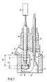
- the metering device has a metering housing 1 with a product inlet 2 and a product outlet 3.
- the product inlet 2 and the product outlet 3 are controlled by a shut-off device 4, which in the exemplary embodiment shown consists of a rotatable valve body 5 and a valve rod 6 , which can be rotated by a drive, not shown, so that the valve body 5 can be brought into a position that closes the product outlet 3, as shown in FIG. 1, and on the other hand can be moved into an open position, as is shown in FIGS 4 and 5 is shown.
- a metering piston 7 is slidably mounted, which is shown schematically by means of a piston rod 8 in FIG adjusting device 9 is connected.
- a front dose chamber 11 and a rear dose chamber 12 are formed by the metering piston 7 in the metering cylinder 6. While the front dose space 11 is only connected to the product inlet when the valve body 5 is in the appropriate position (FIG. 1), the rear dose space 12 is in constant communication with the product inlet 2.
- metering piston 7 is shown in its lowest position with solid lines.
- the normal stroke range of the metering piston 7 in the metering cylinder 6 is designated by I, the top dead center position of the metering piston 7 being indicated in dash-dotted lines.
- the metering piston 7 can be displaced in its entire stroke range during the product suction, e.g. B. in the stroke range designated II.
- the new dead center positions of the metering piston 7 are drawn with dashed lines.
- the metering piston 7 can move between the normal stroke range I and the new stroke range II either stepwise or step by step or also continuously during the suction phase, with the result that the dose spaces 11 and 12 with the metering piston 7 so that the product is exchanged well. In this way, in particular in the rear dose space 12, it is avoided that outdated or segregated product can arise.
- the displacement of the stroke range of the metering piston after certain intervals, for. B. be performed after every third suction stroke.
- the shift can take place continuously, for. B. in such a way that starting from the normal bottom dead center, the metering piston is shifted to the new top dead center. The dosing piston is then adjusted from this position to the new bottom dead center. Then the dosing piston is sucked up to the old upper one Dead center and finally the ejection movement to the old bottom dead center.
- the metering piston can also be moved continuously between the above-mentioned extreme dead centers, but the stroke range always remains the same. Regardless of this, as is known, top dead center can of course be shifted in order to change the output volume as required.
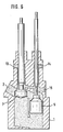
- the dosing device works as follows:
- the metering piston 7 is in its lowest position.
- the shut-off element 4 is in its position with its valve body 5 such that the product outlet 3 is closed, whereas the product inlet 2 is connected to the front dose space 11 via the shut-off element 4.
- the metering piston 7 is then, starting from FIG. 2, moved into the position according to FIG. 3, which shows the end of the suction stroke.
- valve body 5 is rotated via the valve rod 6 so that the connection between the product inlet and the front dose space 11 is blocked by the valve body 5 and at the same time the latter comes into connection with the product outlet 3, as shown in FIG. 4.
- the metering piston 7 is now at the beginning of the ejection position. As can be seen from FIG. 5, the metering piston 7 is moved downward and the product is expelled from the outlet opening 3 into a container (not shown).
- the metering device can be brought into the cleaning position shown in FIG. 6, in which both the metering piston 7 and the valve body 5 have been moved upwards.
- Cleaning liquid can be introduced into the dosing device via the product inlet 2 and additional inlet openings 13, 14 and 15, so that all parts of the metering device are thoroughly washed.
- a push spindle drive does not necessarily have to be provided as the adjusting device, but the adjustment or displacement of the stroke range of the metering piston can also be achieved by an adjusting device, the drive of which is tapped off directly by the dosing drive or by other separate drives, such as, for. B. hydraulic or pneumatic cylinders with a suitable control valve device. It is only important that the stroke range of the metering piston during the suction of the product at certain intervals, for. B. after every fifth suction process or continuously, i.e. is shifted in the dosing cylinder with every suction stroke, so that a secure exchange of the product is achieved in all dosing rooms.
Landscapes
- Physics & Mathematics (AREA)
- Fluid Mechanics (AREA)
- General Physics & Mathematics (AREA)
- Engineering & Computer Science (AREA)
- Mechanical Engineering (AREA)
- Basic Packing Technique (AREA)
- Supply Of Fluid Materials To The Packaging Location (AREA)
Description
- Die Erfindung bezieht sich zunächst auf ein Verfahren zum dosierten Abfüllen von flüssigen und pastösen Produkten, insbesondere Nahrungsmitteln oder dgl., mit einem den Produktzulauf und Produktablauf steuernden, verstellbaren Absperrorgan und einem zwischen einer Ansaugstellung und Ausstoßstellung in einem Dosiergehäuse hin- und herbeweglich gelagerten Dosierkolben, wobei ein auf der Vorderseite des Dosierkolbens liegender Doseurraum während des Ansaugens über das Absperrorgan und ein auf der Rückseite des Dosierkolbens liegender Doseurraum ständig mit dem Produktzulauf in Verbindung steht.
- Ein Verfahren der eingangs genannten Art geht aus der deutschen Patentschrift 29 00 851 hervor. Die dort dargestellte Vorrichtung ist zur volumetrischen Dosierung pastöser Stoffe vorgesehen. Die bekannte Vorrichtung arbeitet in der Weise, daß durch den Dosierkolben bei seinem Aufwärtshub die abzufüllende Paste kolbenseitig, d.h. mit seiner größeren Kolbenfläche über den Doseurraum angesaugt wird, der über das Absperrorgan mit dem Produktzulauf verbunden ist. Sobald der Dosierkolben seinen oberen Totpunkt erreicht hat, wird durch das Absperrorgan der Produktzulauf vom vorgenannten Doseurraum getrennt und letzterer durch entsprechende Verstellung des Steuerkolbens des Absperrorgans mit dem Produktablauf verbunden. Bei dem nun folgenden Abwärtsbewegen des Dosierkolbens stößt dieser die abzufüllende Produktmenge über den Produktablauf in den Abfüllbehälter. Sobald der Dosierkolben seine untere Totpunktstellung erreicht hat, wird das Absperrorgan über den damit verbundenen Steuerkolben derart verstellt, daß der Produktablauf vom Doseurraum getrennt wird und letzterer wiederum mit dem Produktzulauf in Verbindung gebracht wird. Daraufhin erfolgt ein erneuter Aufwärtsgang des Dosierkolbens, um wiederum Produkt aus dem Produktzulauf anzusaugen.
- Obwohl sich Vorrichtungen der vorgenannten Art bzw. nach dem eingangs erläuterten Verfahren betriebene Doseure an sich in der Praxis gut bewährt haben, gibt es dann Probleme, wenn keimarme Produkte abgefüllt werden sollen. Das ist deshalb der Fall, weil der auf der rückwärtigen Seite des Dosierkolbens liegende Doseurraum ständig mit Produkt gefüllt ist und es hier durchaus zu einer Reinfektion aus dem Produktionsprozeß kommen kann, sofern nicht ein ständiger gesicherter Austausch des Produktes gewährleistet ist. Auch beim Abfüllen von Produkten, die entweder zur Entmischung oder zum Festsetzen in den Zuleitungen neigen, kann es Schwierigkeiten geben, die insbesondere aufgrund der diskontinuierlichen Betriebsweise der bekannten Vorrichtung auftreten, wenn der Dosierkolben während seiner Abwärtsbewegung das Produkt ausstößt.
- Der Erfindung liegt die Aufgabe zugrunde, ein zum dosierten Abfüllen von flüssigen und pastösen Produkten, insbesondere Nahrungsmitteln oder dgl. geeignetes Verfahren vorzuschlagen, durch das mit besonders einfachen Mitteln ein gesicherter Austausch des Produktes in allen Doseurräumen gewährleistet ist, so daß kein überaltertes bzw. entmischtes und gegebenenfalls reinfektioniertes Produkt unkontrolliert ausgestoßen wird. Gleichfalls liegt der Erfindung die Aufgabe zugrunde, zur Durchführung des Verfahrens eine geeignete Vorrichtung zu schaffen, die sich durch einen besonders einfachen Aufbau auszeichnet.
- Die der Erfindung zugrundeliegende Aufgabe wird in verfahrensmäßiger Hinsicht zunächst dadurch gelöst, daß der Hubbereich bzw. der untere und obere Totpunkt des Dosierkolbens während der Ansaugung des Produktes ohne Veränderung des Dosierhubs verlagert wird. Die der Erfindung zugrundeliegende Idee ist also die, den unteren und oberen Totpunkt während des Ansaugens des Produktes wandern zu lassen, ohne daß der Dosierhub verändert wird. Die Verlagerung des Hubbereiches bzw. des unteren und oberen Totpunktes des Dosierkolbens kann stufenweise bzw. schrittweise oder aber auch stufenlos erfolgen. Das bedeutet, daß je nach abzufüllendem Produkt, insbesondere dessen Viskosität jeweils der untere und obere Totpunkt, ohne daß dabei der Dosierhub verändert wird, in bestimmten Zeitintervallen oder fortlaufend verlagert werden, so daß das Produkt, insbesondere im Hinterkolbenraum ständig in Bewegung ist und ausgetauscht wird. Somit wird kein überaltertes bzw. entmischtes Produkt unkontrolliert ausgestoßen. Auch ist dadurch ein Reinfektion aus dem Produktionsprozeß ausgeschlossen, d.h. es kann keine Vermehrung der Keime des keimarmen Produktes stattfinden.
- Eine zum Durchführen des erfindungsgemäßen Verfahrens geeignete Vorrichtung zum dosierten Abfüllen von flüssigen und pastösen Produkten, insbesondere Nahrungsmitteln mit einem den Produktzulauf und Produktablauf steuernden verstellbaren Absperrorgan und einem zwischen einer Ansaugstellung und Ausstoßstellung in einem Dosiergehäuse hin- und herbeweglich gelagerten Dosierkolben zeichnet sich durch eine Verstelleinrichtung zur axialen Verlagerung der unveränderten Hubstrecke des Dosierkolbens während der Ansaugphase des Doseurs aus. An sich ist jede beliebige Antriebs- bzw. Verstelleinrichtung denkbar, die in der Lage ist, jeweils nach gewünschter Zeit oder ständig eine im vorgegebenen Rahmen bestimmte Verlagerung des Hubbereichs des Dosierkolbens vorzunehmen. So eignen sich als Verstellvorrichtung durchaus handelsübliche elektromotorisch angetriebene, zeitgesteuerte Schubspindelantriebe. Der Antrieb für die Verstelleinrichtung kann auch vom Doseurantrieb abgezapft werden oder durch sonstige separate Antriebe, wie z. B. hydraulische und pneumatische Zylinder-Kolben-Einheiten ausgebildet sein. Auch ist es denkbar, die erfindungsgemäße Verstellagerung des Hubbereichs des Dosierkolbens z. B. mittels einer programmierten Speichersteuerung vollautomatisch ablaufen zu lassen.
- Ein bevorzugtes Ausführungsbeispiel der Erfindung ist in der Zeichnung dargestellt und wird im folgenden näher erläutert:
- Es zeigen in jeweils schematischer Darstellung:
- Fig. 1 Die nach der Erfindung ausgebildete Dosiervorrichtung mit der Verstell-Lagerung des Dosierkolbens in einer senkrechten Schnittdarstellung,
- Fig. 2 die Dosiervorrichtung zu Beginn des Ansaughubes,
- Fig. 3 die Vorrichtung am Ende des Ansaughubes,
- Fig. 4 den Beginn des Auspressens,
- Fig. 5 das Ende des Auspressens und
- Fig. 6 die Dosiervorrichtung in der Reinigungsstellung.
- Wie aus Fig. 1 hervorgeht, besitzt die Dosiervorrichtung ein Dosiergehäuse 1 mit einem Produktzulauf 2 und einem Produktablauf 3. Der Produktzulauf 2 und der Produktablauf 3 sind durch ein Absperrorgan 4 gesteuert, welches im dargestellten Ausführungsbeispiel aus einem drehbaren Ventilkörper 5 und einer Ventilstange 6 besteht, die von einem nicht dargestellten Antrieb verdreht werden kann, so daß der Ventilkörper 5 einmal in eine den Produktablauf 3 verschließende Stellung gebracht werden kann, so wie in Fig. 1 dargestellt und zum anderen in eine Offenstellung bewegt werden kann, so wie dies in den Fig. 4 und 5 gezeigt ist.
- In einem im wesentlichen parallel zum Absperrorgan verlaufenden Dosierzylinder 6 ist ein Dosierkolben 7 gleitbeweglich gelagert, der über eine Kolbenstange 8 mit einer in Fig. 1 schematisch dargestellten Verstelleinrichtung 9 verbunden ist. Durch den Dosierkolben 7 wird im Dosierzylinder 6 ein vorderer Doseurraum 11 und ein hinterer Doseurraum 12 gebildet. Während der vordere Doseurraum 11 nur bei entsprechender Stellung (Fig. 1) des Ventilkörpers 5 mit dem Produktzulauf verbunden ist steht der hintere Doseurraum 12 mit dem Produktzulauf 2 ständig in Verbindung.
- In Fig. 1 ist der Dosierkolben 7 mit ausgezogenen Linien in seiner untersten Stellung gezeigt. Der normale Hubbereich des Dosierkolbens 7 im Dosierzylinder 6 ist mit I bezeichnet, wobei die obere Totpunktlage des Dosierkolbens 7 in strichpunktierten Linien angedeutet ist. Durch die Verstelleinrichtung 9, beispielsweise einen handelsüblichen, elektromotorisch und zeitabhängig gesteuerten Schubspindelantrieb mit Endanschlägen kann der Dosierkolben 7 während der Produktansaugung in seinem gesamten Hubbereich verlagert werden, z. B. in den mit II bezeichneten Hubbereich. Die neuen Totpunktlagen des Dosierkolbens 7 sind mit gestrichelten Linien gezeichnet. Das bedeutet, daß aufgrund einer entsprechenden Steuerung, die auch programmgespeichert sein kann, der Dosierkolben 7 während der Ansaugphase zwischen dem normalen Hubbereich I und dem neuen Hubbereich II entweder stufenweise bzw. schrittweise oder aber auch stufenlos wandern kann, mit der Folge, daß die Doseurräume 11 und 12 mit dem Dosierkolben 7 so beaufschlagt werden, daß das Produkt gut ausgetauscht wird. Hierdurch wird insbesondere im hinteren Doseurraum 12 vermieden, daß überaltertes bzw. entmischtes Produkt entstehen kann.
- In konkreter Ausführung der Erfindung kann die Verlagerung des Hubbereichs des Dosierkolbens nach bestimmten Intervallen, z. B. nach jedem dritten Ansaughub durchgeführt werden. Ebenso kann die Verlagerung stetig erfolgen, z. B. in der Weise, daß ausgehend vom normalen unteren Totpunkt der Dosierkolben bis zum neuen oberen Totpunkt verlagert wird. Von dieser Position aus wird dann der Dosierkolben bis zum neuen unteren Totpunkt verstellt. Danach erfolgt eine Ansaugbewegung des Dosierkolbens bis zum alten oberen Totpunkt und schließlich die Ausstoßbewegung bis zum alten unteren Totpunkt. Selbstverständlich kann man bei entsprechender Steuerung den Dosierkolben auch stufenlos zwischen den vorstehend genannten Extremtotpunkten wandern lassen, wobei der Hubbereich jedoch stets gleich bleibt. Unabhängig davon kann natürlich - wie bekannt - der obere Totpunkt verlagert werden, um das Ausstoßvolumen je nach Bedarf zu verändern.
- Die Wirkungsweise der Dosiervorrichtung ist wie folgt:
- Ausgehend von der in Fig. 1 dargestellten Stellung, d.h. bei Beginn des Ansaugens steht der Dosierkolben 7 in seiner untersten Stellung. Das Absperrorgan 4 ist mit seinem Ventilkörper 5 in einer solchen Stellung, daß der Produktauslauf 3 abgeschlossen ist, hingegen der Produktzulauf 2 über das Absperrorgan 4 mit dem vorderen Doseurraum 11 in Verbindung steht. Der Dosierkolben 7 wird dann, ausgehend von der Fig. 2, in die Stellung nach Fig. 3 bewegt, welche das Ende des Ansaughubes zeigt.
- Daraufhin wird der Ventilkörper 5 über die Ventilstange 6 so verdreht, daß durch den Ventilkörper 5 die Verbindung zwischen dem Produktzulauf und dem vorderen Doseurraum 11 abgesperrt wird und gleichzeitig letzterer mit dem Produktablauf 3 in Verbindung gelangt, so wir das in Fig. 4 gezeigt ist. Der Dosierkolben 7 befindet sich nun zu Beginn der Ausstoßstellung. Wie aus Fig. 5 hervorgeht, wird der Dosierkolben 7 nach unten bewegt und dabei das Produkt aus der Auslauföffnung 3 in einen nicht dargestellten Behälter ausgestoßen.
- Zu Reinigungszwecken kann die Dosiervorrichtung in die in Fig. 6 gezeigte Reinigungsstellung gebracht werden, in welcher sowohl der Dosierkolben 7 als auch der Ventilkörper 5 nach oben bewegt worden sind. Über den Produktzulauf 2 und zusätzliche Einlauföffnungen 13, 14 und 15 kann Reinigungsflüssigkeit in den Doseur eingebracht werden, so daß alle Teile der Dosiervorrichtung gut umspült werden.
- Es versteht sich, daß die Erfindung nicht nur auf das dargestellten Ausführungsbeispiel beschränkt ist, sondern im Rahmen der Ansprüche auch Änderungen zulässig sind. So braucht als Verstelleinrichtung nicht unbedingt ein Schubspindelantrieb vorgesehen sein, sondern die Verstellung bzw. Verlagerung des Hubbereichs des Dosierkolbens kann auch von einer Verstelleinrichtung erzielt werden, deren Antrieb direkt vom Doseurantrieb abgezapft wird oder aber durch sonstige separate Antriebe, wie z. B. hydraulische oder pneumatische Zylinder mit geeigneter Steuerventileinrichtung. Wesentlich ist nur, daß der Hubbereich des Dosierkolbens während des Ansaugens des Produktes in bestimmten Intervallen, z. B. nach jedem fünften Ansaugvorgang oder aber ständig, d.h. bei jedem Ansaughub im Dosierzylinder verlagert wird, so daß ein gesicherter Austausch des Produktes in allen Doseurräumen erreicht wird.
Claims (6)
Applications Claiming Priority (2)
| Application Number | Priority Date | Filing Date | Title |
|---|---|---|---|
| DE3919913 | 1989-06-19 | ||
| DE3919913A DE3919913C1 (de) | 1989-06-19 | 1989-06-19 |
Publications (2)
| Publication Number | Publication Date |
|---|---|
| EP0403813A1 EP0403813A1 (de) | 1990-12-27 |
| EP0403813B1 true EP0403813B1 (de) | 1992-08-12 |
Family
ID=6383003
Family Applications (1)
| Application Number | Title | Priority Date | Filing Date |
|---|---|---|---|
| EP90109756A Expired - Lifetime EP0403813B1 (de) | 1989-06-19 | 1990-05-22 | Verfahren und Vorrichtung zum dosierten Abfüllen von flüssigen und pastösen Produkten, insbesondere Nahrungsmitteln oder dergleichen |
Country Status (4)
| Country | Link |
|---|---|
| US (1) | US5019127A (de) |
| EP (1) | EP0403813B1 (de) |
| DE (2) | DE3919913C1 (de) |
| DK (1) | DK0403813T3 (de) |
Families Citing this family (12)
| Publication number | Priority date | Publication date | Assignee | Title |
|---|---|---|---|---|
| DE4226566C2 (de) * | 1992-08-12 | 1996-04-18 | Jagenberg Ag | Vorrichtung zum Dosieren und Abfüllen von flüssigen oder pastösen Produkten |
| DE59800608D1 (de) * | 1997-08-18 | 2001-05-17 | Benhil Gasti Verpackungsmaschi | Vorrichtung und Verfahren zum dosierten Abfüllen von flüssigen bis pastösen Produkten |
| EP0994333A1 (de) * | 1998-10-16 | 2000-04-19 | Comas S.p.a. | Vorrichtung zur Volumenmessung von flüssigen Producten, insbesondere von Nahrungsproducten |
| WO2000064770A2 (en) * | 1999-04-27 | 2000-11-02 | Stumler Irvin H | Dispensing machine with portion control |
| US6814109B2 (en) * | 2003-01-03 | 2004-11-09 | Packaging Technologies, Inc. | Zero clearance rotor valve for product filling |
| ITTO20070680A1 (it) * | 2007-09-27 | 2009-03-28 | Francesco Bonato | "dispositivo dosatore di sostanze alimentari liquide o pastose" |
| DE102008028772A1 (de) * | 2008-06-17 | 2009-12-24 | Hansen, Bernd, Dipl.-Ing. | Vorrichtung zum Befüllen von Behältnissen |
| RU2589346C2 (ru) * | 2011-03-31 | 2016-07-10 | Фишман Корпорейшн | Система и способ для точной подачи управляемых количеств вязкой текучей среды к устройству подачи текучей среды |
| DE102011119455A1 (de) * | 2011-11-28 | 2013-05-29 | Robert Bosch Gmbh | Vorrichtung zum gleichzeitigen Füllen von mindestens zwei Nahrungsmitteln unterschiedlicher Beschaffenheit in einen Behälter |
| DE102013109969A1 (de) * | 2013-09-11 | 2015-03-12 | Krones Ag | Vorrichtung zum Dosieren eines Füllprodukts in einen zu befüllenden Behälter |
| US20170208997A1 (en) * | 2014-07-18 | 2017-07-27 | Pi-Design Ag | Kitchen appliance for processing foodstuff |
| DE102018113421A1 (de) * | 2018-06-06 | 2019-12-12 | Prominent Gmbh | Dosierpumpe mit Linearmotor |
Family Cites Families (14)
| Publication number | Priority date | Publication date | Assignee | Title |
|---|---|---|---|---|
| FR1278869A (fr) * | 1961-01-13 | 1961-12-15 | Mec Carlo Migliavacca & C Soc | Dispositif pour l'alimentation et le dosage automatique de produits en poudre, granuleux ou liquides notamment de confiture |
| US3168225A (en) * | 1961-03-06 | 1965-02-02 | Chemetron Corp | Valve arrangement for receptacle filling machines |
| US3865281A (en) * | 1970-05-18 | 1975-02-11 | Owens Illinois Inc | Apparatus for filling containers |
| DE2308689A1 (de) * | 1973-02-22 | 1974-09-05 | Breitner Abfuellanlagen Kg Mas | Abfuelleinrichtung fuer fluessige medien |
| US3833155A (en) * | 1973-09-07 | 1974-09-03 | Phillips Petroleum Co | Positive displacement liquid dispensing mechanism |
| US3850345A (en) * | 1973-11-28 | 1974-11-26 | Fmc Corp | Filling valve |
| US4076482A (en) * | 1976-03-04 | 1978-02-28 | Whetstone Henry M | Charge forming and depositing machine |
| DE2658147A1 (de) * | 1976-12-22 | 1978-07-06 | Bosch Gmbh Robert | Dosiervorrichtung zum keimfreien abmessen und abfuellen von fluessigem gut |
| DE2900851C2 (de) * | 1979-01-11 | 1984-09-20 | Bayer Ag, 5090 Leverkusen | Vorrichtung zur volumetrischen Dosierung pastöser Stoffe |
| US4399932A (en) * | 1981-06-02 | 1983-08-23 | Guenter Zimmermann | Volumetric metering valve |
| US4437498A (en) * | 1981-11-09 | 1984-03-20 | Liquipak International, Inc. | Carton filling apparatus |
| DE3443557A1 (de) * | 1984-11-29 | 1986-05-28 | Lieder Maschinenbau GmbH & Co KG, 3033 Schwarmstedt | Verfahren und vorrichtung zur abmessung eines fliessfaehigen produktes |
| NL8501983A (nl) * | 1985-07-10 | 1987-02-02 | Stork Bepak Bv | Plunjerdoseerinrichting. |
| DE3636804C1 (de) * | 1986-10-29 | 1988-05-26 | Benz & Hilgers Gmbh | Vorrichtung zum dosierten Abfuellen von fliessfaehigem oder pastoesem Fuellgut in Behaelter |
-
1989
- 1989-06-19 DE DE3919913A patent/DE3919913C1/de not_active Expired - Fee Related
-
1990
- 1990-05-22 DE DE9090109756T patent/DE59000250D1/de not_active Expired - Fee Related
- 1990-05-22 EP EP90109756A patent/EP0403813B1/de not_active Expired - Lifetime
- 1990-05-22 DK DK90109756.8T patent/DK0403813T3/da active
- 1990-05-23 US US07/528,127 patent/US5019127A/en not_active Expired - Fee Related
Also Published As
| Publication number | Publication date |
|---|---|
| US5019127A (en) | 1991-05-28 |
| DK0403813T3 (da) | 1992-12-07 |
| DE3919913C1 (de) | 1990-04-26 |
| DE59000250D1 (de) | 1992-09-17 |
| EP0403813A1 (de) | 1990-12-27 |
Similar Documents
| Publication | Publication Date | Title |
|---|---|---|
| DE2303436C2 (de) | Formmaschine | |
| EP0061472B1 (de) | Kaffeemaschine | |
| DE3309964C2 (de) | Vorrichtung zum Dosieren und Mischen von zwei oder mehreren fließfähigen Kunststoff-Reaktionskomponenten | |
| EP0403813B1 (de) | Verfahren und Vorrichtung zum dosierten Abfüllen von flüssigen und pastösen Produkten, insbesondere Nahrungsmitteln oder dergleichen | |
| DD241189A5 (de) | Verfahren zum injizieren viskoser fluessigkeit in brot oder konditoreiwaren | |
| DE3402136A1 (de) | Fuellvorrichtung | |
| DE3636804C1 (de) | Vorrichtung zum dosierten Abfuellen von fliessfaehigem oder pastoesem Fuellgut in Behaelter | |
| DE2821801A1 (de) | Ventilanordnung mit einem membranventil | |
| EP1515611B1 (de) | Verfahren und vorrichtung zur dosierung und einbringung von zutaten in eine knetmaschine | |
| DE3878749T2 (de) | Fuelleinrichtung fuer fluessigkeiten. | |
| EP1602579B1 (de) | Anlage zum Befüllen von Nahrungsmittelbechern | |
| DE102008055813B3 (de) | Vorrichtung und Verfahren zum Dosieren von Süßwarenmassen | |
| EP0793566B1 (de) | Vorrichtung zum dosierten zuführen der einzelkomponenten von flüssigem mehrkomponenten-kunststoff an einen mischkopf | |
| EP1494920B1 (de) | Dosiervorrichtung für fliessfähige produkte | |
| DE3630077C2 (de) | ||
| DE2415237C3 (de) | Vorrichtung zum dosierten Abfüllen von flüssigen, im Ruhezustand erstarrenden Stoffen, wie Margarine o.dl. | |
| DE1966542C3 (de) | Anlage zur Verarbeitung von Gießharz | |
| DE69410066T2 (de) | Modulares Dosiergerät | |
| AT351480B (de) | Maschine zum abteilen von teigstuecken | |
| DE2461892A1 (de) | Kontinuierlich arbeitende maschine zum herstellen von gleichen teigteilchen | |
| EP0287968A2 (de) | Verfahren und Vorrichtung zum Dosieren und Mischen von Mehrkomponenten-Kunststoffen, insbesondere Polyurethan | |
| DE2262254A1 (de) | Verfahren und vorrichtung zum dosieren der bindemittelzugaben bei der herstellung von sandformen und -kernen fuer giessereizwecke | |
| DE2824680A1 (de) | Vorrichtung zum dosieren und abfuellen insbesondere hochviskoser medien | |
| DE3227616C2 (de) | ||
| DE60312278T2 (de) | Vorrichtung zur Herstellung von Silikon aus zwei Komponenten |
Legal Events
| Date | Code | Title | Description |
|---|---|---|---|
| PUAI | Public reference made under article 153(3) epc to a published international application that has entered the european phase |
Free format text: ORIGINAL CODE: 0009012 |
|
| AK | Designated contracting states |
Kind code of ref document: A1 Designated state(s): CH DE DK FR GB LI |
|
| 17P | Request for examination filed |
Effective date: 19910126 |
|
| 17Q | First examination report despatched |
Effective date: 19911212 |
|
| GRAA | (expected) grant |
Free format text: ORIGINAL CODE: 0009210 |
|
| AK | Designated contracting states |
Kind code of ref document: B1 Designated state(s): CH DE DK FR GB LI |
|
| REF | Corresponds to: |
Ref document number: 59000250 Country of ref document: DE Date of ref document: 19920917 |
|
| GBT | Gb: translation of ep patent filed (gb section 77(6)(a)/1977) | ||
| ET | Fr: translation filed | ||
| REG | Reference to a national code |
Ref country code: DK Ref legal event code: T3 |
|
| PLBE | No opposition filed within time limit |
Free format text: ORIGINAL CODE: 0009261 |
|
| STAA | Information on the status of an ep patent application or granted ep patent |
Free format text: STATUS: NO OPPOSITION FILED WITHIN TIME LIMIT |
|
| 26N | No opposition filed | ||
| PGFP | Annual fee paid to national office [announced via postgrant information from national office to epo] |
Ref country code: DE Payment date: 19940419 Year of fee payment: 5 |
|
| PGFP | Annual fee paid to national office [announced via postgrant information from national office to epo] |
Ref country code: FR Payment date: 19940420 Year of fee payment: 5 Ref country code: CH Payment date: 19940420 Year of fee payment: 5 |
|
| PGFP | Annual fee paid to national office [announced via postgrant information from national office to epo] |
Ref country code: GB Payment date: 19940421 Year of fee payment: 5 |
|
| PGFP | Annual fee paid to national office [announced via postgrant information from national office to epo] |
Ref country code: DK Payment date: 19940630 Year of fee payment: 5 |
|
| PG25 | Lapsed in a contracting state [announced via postgrant information from national office to epo] |
Ref country code: GB Effective date: 19950522 Ref country code: DK Effective date: 19950522 |
|
| REG | Reference to a national code |
Ref country code: DK Ref legal event code: EBP |
|
| PG25 | Lapsed in a contracting state [announced via postgrant information from national office to epo] |
Ref country code: LI Effective date: 19950531 Ref country code: CH Effective date: 19950531 |
|
| GBPC | Gb: european patent ceased through non-payment of renewal fee |
Effective date: 19950522 |
|
| REG | Reference to a national code |
Ref country code: CH Ref legal event code: PL |
|
| PG25 | Lapsed in a contracting state [announced via postgrant information from national office to epo] |
Ref country code: DE Effective date: 19960201 |
|
| PG25 | Lapsed in a contracting state [announced via postgrant information from national office to epo] |
Ref country code: FR Effective date: 19960229 |
|
| REG | Reference to a national code |
Ref country code: FR Ref legal event code: ST |
|
| REG | Reference to a national code |
Ref country code: FR Ref legal event code: ST |