EP0403686B1 - Rohr, insbesondere für eine Umlenkwelle, Expansionswelle oder dergleichen - Google Patents
Rohr, insbesondere für eine Umlenkwelle, Expansionswelle oder dergleichen Download PDFInfo
- Publication number
- EP0403686B1 EP0403686B1 EP89113332A EP89113332A EP0403686B1 EP 0403686 B1 EP0403686 B1 EP 0403686B1 EP 89113332 A EP89113332 A EP 89113332A EP 89113332 A EP89113332 A EP 89113332A EP 0403686 B1 EP0403686 B1 EP 0403686B1
- Authority
- EP
- European Patent Office
- Prior art keywords
- fiber
- tube
- coat
- fibers
- pipe section
- Prior art date
- Legal status (The legal status is an assumption and is not a legal conclusion. Google has not performed a legal analysis and makes no representation as to the accuracy of the status listed.)
- Expired - Lifetime
Links
- 239000000463 material Substances 0.000 claims abstract description 18
- 239000000835 fiber Substances 0.000 claims description 29
- 229920000049 Carbon (fiber) Polymers 0.000 claims description 20
- 239000004917 carbon fiber Substances 0.000 claims description 20
- 239000004760 aramid Substances 0.000 claims description 3
- 229920006231 aramid fiber Polymers 0.000 claims description 3
- 238000010276 construction Methods 0.000 claims description 2
- 239000011347 resin Substances 0.000 claims 3
- 229920005989 resin Polymers 0.000 claims 3
- 229920006395 saturated elastomer Polymers 0.000 claims 2
- 229920003002 synthetic resin Polymers 0.000 abstract description 5
- 239000000057 synthetic resin Substances 0.000 abstract description 5
- 238000000034 method Methods 0.000 abstract description 2
- OKTJSMMVPCPJKN-UHFFFAOYSA-N Carbon Chemical compound [C] OKTJSMMVPCPJKN-UHFFFAOYSA-N 0.000 abstract 1
- 229910052799 carbon Inorganic materials 0.000 abstract 1
- 239000004744 fabric Substances 0.000 description 13
- VNWKTOKETHGBQD-UHFFFAOYSA-N methane Chemical compound C VNWKTOKETHGBQD-UHFFFAOYSA-N 0.000 description 13
- 241000264877 Hippospongia communis Species 0.000 description 12
- 229910000831 Steel Inorganic materials 0.000 description 6
- 239000010959 steel Substances 0.000 description 6
- 240000006240 Linum usitatissimum Species 0.000 description 4
- 244000089486 Phragmites australis subsp australis Species 0.000 description 3
- 238000005452 bending Methods 0.000 description 3
- FZNCGRZWXLXZSZ-CIQUZCHMSA-N Voglibose Chemical compound OCC(CO)N[C@H]1C[C@](O)(CO)[C@@H](O)[C@H](O)[C@H]1O FZNCGRZWXLXZSZ-CIQUZCHMSA-N 0.000 description 2
- 230000001154 acute effect Effects 0.000 description 2
- 239000003795 chemical substances by application Substances 0.000 description 1
- 239000013065 commercial product Substances 0.000 description 1
- 239000003365 glass fiber Substances 0.000 description 1
- 239000007788 liquid Substances 0.000 description 1
- 239000004033 plastic Substances 0.000 description 1
- 239000007787 solid Substances 0.000 description 1
- 125000006850 spacer group Chemical group 0.000 description 1
- 230000003068 static effect Effects 0.000 description 1
Images

Classifications
-
- B—PERFORMING OPERATIONS; TRANSPORTING
- B29—WORKING OF PLASTICS; WORKING OF SUBSTANCES IN A PLASTIC STATE IN GENERAL
- B29D—PRODUCING PARTICULAR ARTICLES FROM PLASTICS OR FROM SUBSTANCES IN A PLASTIC STATE
- B29D23/00—Producing tubular articles
- B29D23/001—Pipes; Pipe joints
-
- B—PERFORMING OPERATIONS; TRANSPORTING
- B29—WORKING OF PLASTICS; WORKING OF SUBSTANCES IN A PLASTIC STATE IN GENERAL
- B29C—SHAPING OR JOINING OF PLASTICS; SHAPING OF MATERIAL IN A PLASTIC STATE, NOT OTHERWISE PROVIDED FOR; AFTER-TREATMENT OF THE SHAPED PRODUCTS, e.g. REPAIRING
- B29C53/00—Shaping by bending, folding, twisting, straightening or flattening; Apparatus therefor
- B29C53/56—Winding and joining, e.g. winding spirally
- B29C53/58—Winding and joining, e.g. winding spirally helically
- B29C53/583—Winding and joining, e.g. winding spirally helically for making tubular articles with particular features
- B29C53/587—Winding and joining, e.g. winding spirally helically for making tubular articles with particular features having a non-uniform wall-structure, e.g. with inserts, perforations, locally concentrated reinforcements
-
- B—PERFORMING OPERATIONS; TRANSPORTING
- B29—WORKING OF PLASTICS; WORKING OF SUBSTANCES IN A PLASTIC STATE IN GENERAL
- B29D—PRODUCING PARTICULAR ARTICLES FROM PLASTICS OR FROM SUBSTANCES IN A PLASTIC STATE
- B29D23/00—Producing tubular articles
- B29D23/001—Pipes; Pipe joints
- B29D23/003—Pipe joints, e.g. straight joints
-
- B—PERFORMING OPERATIONS; TRANSPORTING
- B29—WORKING OF PLASTICS; WORKING OF SUBSTANCES IN A PLASTIC STATE IN GENERAL
- B29D—PRODUCING PARTICULAR ARTICLES FROM PLASTICS OR FROM SUBSTANCES IN A PLASTIC STATE
- B29D24/00—Producing articles with hollow walls
- B29D24/002—Producing articles with hollow walls formed with structures, e.g. cores placed between two plates or sheets, e.g. partially filled
- B29D24/005—Producing articles with hollow walls formed with structures, e.g. cores placed between two plates or sheets, e.g. partially filled the structure having joined ribs, e.g. honeycomb
-
- F—MECHANICAL ENGINEERING; LIGHTING; HEATING; WEAPONS; BLASTING
- F16—ENGINEERING ELEMENTS AND UNITS; GENERAL MEASURES FOR PRODUCING AND MAINTAINING EFFECTIVE FUNCTIONING OF MACHINES OR INSTALLATIONS; THERMAL INSULATION IN GENERAL
- F16L—PIPES; JOINTS OR FITTINGS FOR PIPES; SUPPORTS FOR PIPES, CABLES OR PROTECTIVE TUBING; MEANS FOR THERMAL INSULATION IN GENERAL
- F16L9/00—Rigid pipes
- F16L9/12—Rigid pipes of plastics with or without reinforcement
-
- B—PERFORMING OPERATIONS; TRANSPORTING
- B29—WORKING OF PLASTICS; WORKING OF SUBSTANCES IN A PLASTIC STATE IN GENERAL
- B29K—INDEXING SCHEME ASSOCIATED WITH SUBCLASSES B29B, B29C OR B29D, RELATING TO MOULDING MATERIALS OR TO MATERIALS FOR MOULDS, REINFORCEMENTS, FILLERS OR PREFORMED PARTS, e.g. INSERTS
- B29K2307/00—Use of elements other than metals as reinforcement
-
- Y—GENERAL TAGGING OF NEW TECHNOLOGICAL DEVELOPMENTS; GENERAL TAGGING OF CROSS-SECTIONAL TECHNOLOGIES SPANNING OVER SEVERAL SECTIONS OF THE IPC; TECHNICAL SUBJECTS COVERED BY FORMER USPC CROSS-REFERENCE ART COLLECTIONS [XRACs] AND DIGESTS
- Y10—TECHNICAL SUBJECTS COVERED BY FORMER USPC
- Y10S—TECHNICAL SUBJECTS COVERED BY FORMER USPC CROSS-REFERENCE ART COLLECTIONS [XRACs] AND DIGESTS
- Y10S138/00—Pipes and tubular conduits
- Y10S138/07—Resins
-
- Y—GENERAL TAGGING OF NEW TECHNOLOGICAL DEVELOPMENTS; GENERAL TAGGING OF CROSS-SECTIONAL TECHNOLOGIES SPANNING OVER SEVERAL SECTIONS OF THE IPC; TECHNICAL SUBJECTS COVERED BY FORMER USPC CROSS-REFERENCE ART COLLECTIONS [XRACs] AND DIGESTS
- Y10—TECHNICAL SUBJECTS COVERED BY FORMER USPC
- Y10T—TECHNICAL SUBJECTS COVERED BY FORMER US CLASSIFICATION
- Y10T156/00—Adhesive bonding and miscellaneous chemical manufacture
- Y10T156/10—Methods of surface bonding and/or assembly therefor
- Y10T156/1002—Methods of surface bonding and/or assembly therefor with permanent bending or reshaping or surface deformation of self sustaining lamina
- Y10T156/1003—Methods of surface bonding and/or assembly therefor with permanent bending or reshaping or surface deformation of self sustaining lamina by separating laminae between spaced secured areas [e.g., honeycomb expanding]
-
- Y—GENERAL TAGGING OF NEW TECHNOLOGICAL DEVELOPMENTS; GENERAL TAGGING OF CROSS-SECTIONAL TECHNOLOGIES SPANNING OVER SEVERAL SECTIONS OF THE IPC; TECHNICAL SUBJECTS COVERED BY FORMER USPC CROSS-REFERENCE ART COLLECTIONS [XRACs] AND DIGESTS
- Y10—TECHNICAL SUBJECTS COVERED BY FORMER USPC
- Y10T—TECHNICAL SUBJECTS COVERED BY FORMER US CLASSIFICATION
- Y10T156/00—Adhesive bonding and miscellaneous chemical manufacture
- Y10T156/10—Methods of surface bonding and/or assembly therefor
- Y10T156/1002—Methods of surface bonding and/or assembly therefor with permanent bending or reshaping or surface deformation of self sustaining lamina
- Y10T156/1028—Methods of surface bonding and/or assembly therefor with permanent bending or reshaping or surface deformation of self sustaining lamina by bending, drawing or stretch forming sheet to assume shape of configured lamina while in contact therewith
- Y10T156/1033—Flexible sheet to cylinder lamina
-
- Y—GENERAL TAGGING OF NEW TECHNOLOGICAL DEVELOPMENTS; GENERAL TAGGING OF CROSS-SECTIONAL TECHNOLOGIES SPANNING OVER SEVERAL SECTIONS OF THE IPC; TECHNICAL SUBJECTS COVERED BY FORMER USPC CROSS-REFERENCE ART COLLECTIONS [XRACs] AND DIGESTS
- Y10—TECHNICAL SUBJECTS COVERED BY FORMER USPC
- Y10T—TECHNICAL SUBJECTS COVERED BY FORMER US CLASSIFICATION
- Y10T156/00—Adhesive bonding and miscellaneous chemical manufacture
- Y10T156/10—Methods of surface bonding and/or assembly therefor
- Y10T156/1052—Methods of surface bonding and/or assembly therefor with cutting, punching, tearing or severing
- Y10T156/1056—Perforating lamina
-
- Y—GENERAL TAGGING OF NEW TECHNOLOGICAL DEVELOPMENTS; GENERAL TAGGING OF CROSS-SECTIONAL TECHNOLOGIES SPANNING OVER SEVERAL SECTIONS OF THE IPC; TECHNICAL SUBJECTS COVERED BY FORMER USPC CROSS-REFERENCE ART COLLECTIONS [XRACs] AND DIGESTS
- Y10—TECHNICAL SUBJECTS COVERED BY FORMER USPC
- Y10T—TECHNICAL SUBJECTS COVERED BY FORMER US CLASSIFICATION
- Y10T428/00—Stock material or miscellaneous articles
- Y10T428/13—Hollow or container type article [e.g., tube, vase, etc.]
- Y10T428/1352—Polymer or resin containing [i.e., natural or synthetic]
- Y10T428/1362—Textile, fabric, cloth, or pile containing [e.g., web, net, woven, knitted, mesh, nonwoven, matted, etc.]
-
- Y—GENERAL TAGGING OF NEW TECHNOLOGICAL DEVELOPMENTS; GENERAL TAGGING OF CROSS-SECTIONAL TECHNOLOGIES SPANNING OVER SEVERAL SECTIONS OF THE IPC; TECHNICAL SUBJECTS COVERED BY FORMER USPC CROSS-REFERENCE ART COLLECTIONS [XRACs] AND DIGESTS
- Y10—TECHNICAL SUBJECTS COVERED BY FORMER USPC
- Y10T—TECHNICAL SUBJECTS COVERED BY FORMER US CLASSIFICATION
- Y10T428/00—Stock material or miscellaneous articles
- Y10T428/13—Hollow or container type article [e.g., tube, vase, etc.]
- Y10T428/1352—Polymer or resin containing [i.e., natural or synthetic]
- Y10T428/139—Open-ended, self-supporting conduit, cylinder, or tube-type article
- Y10T428/1393—Multilayer [continuous layer]
-
- Y—GENERAL TAGGING OF NEW TECHNOLOGICAL DEVELOPMENTS; GENERAL TAGGING OF CROSS-SECTIONAL TECHNOLOGIES SPANNING OVER SEVERAL SECTIONS OF THE IPC; TECHNICAL SUBJECTS COVERED BY FORMER USPC CROSS-REFERENCE ART COLLECTIONS [XRACs] AND DIGESTS
- Y10—TECHNICAL SUBJECTS COVERED BY FORMER USPC
- Y10T—TECHNICAL SUBJECTS COVERED BY FORMER US CLASSIFICATION
- Y10T428/00—Stock material or miscellaneous articles
- Y10T428/23—Sheet including cover or casing
- Y10T428/234—Sheet including cover or casing including elements cooperating to form cells
- Y10T428/236—Honeycomb type cells extend perpendicularly to nonthickness layer
-
- Y—GENERAL TAGGING OF NEW TECHNOLOGICAL DEVELOPMENTS; GENERAL TAGGING OF CROSS-SECTIONAL TECHNOLOGIES SPANNING OVER SEVERAL SECTIONS OF THE IPC; TECHNICAL SUBJECTS COVERED BY FORMER USPC CROSS-REFERENCE ART COLLECTIONS [XRACs] AND DIGESTS
- Y10—TECHNICAL SUBJECTS COVERED BY FORMER USPC
- Y10T—TECHNICAL SUBJECTS COVERED BY FORMER US CLASSIFICATION
- Y10T428/00—Stock material or miscellaneous articles
- Y10T428/24—Structurally defined web or sheet [e.g., overall dimension, etc.]
- Y10T428/24149—Honeycomb-like
-
- Y—GENERAL TAGGING OF NEW TECHNOLOGICAL DEVELOPMENTS; GENERAL TAGGING OF CROSS-SECTIONAL TECHNOLOGIES SPANNING OVER SEVERAL SECTIONS OF THE IPC; TECHNICAL SUBJECTS COVERED BY FORMER USPC CROSS-REFERENCE ART COLLECTIONS [XRACs] AND DIGESTS
- Y10—TECHNICAL SUBJECTS COVERED BY FORMER USPC
- Y10T—TECHNICAL SUBJECTS COVERED BY FORMER US CLASSIFICATION
- Y10T428/00—Stock material or miscellaneous articles
- Y10T428/29—Coated or structually defined flake, particle, cell, strand, strand portion, rod, filament, macroscopic fiber or mass thereof
- Y10T428/2913—Rod, strand, filament or fiber
- Y10T428/2918—Rod, strand, filament or fiber including free carbon or carbide or therewith [not as steel]
- Y10T428/292—In coating or impregnation
-
- Y—GENERAL TAGGING OF NEW TECHNOLOGICAL DEVELOPMENTS; GENERAL TAGGING OF CROSS-SECTIONAL TECHNOLOGIES SPANNING OVER SEVERAL SECTIONS OF THE IPC; TECHNICAL SUBJECTS COVERED BY FORMER USPC CROSS-REFERENCE ART COLLECTIONS [XRACs] AND DIGESTS
- Y10—TECHNICAL SUBJECTS COVERED BY FORMER USPC
- Y10T—TECHNICAL SUBJECTS COVERED BY FORMER US CLASSIFICATION
- Y10T428/00—Stock material or miscellaneous articles
- Y10T428/30—Self-sustaining carbon mass or layer with impregnant or other layer
Definitions
- the invention relates to a tube, in particular for a deflection shaft, expansion shaft and the like, with the features of the preamble of claim 1.
- Deflection shafts are used in the web processing industry, where they serve to deflect the webs processed in the machine in question. They usually consist of steel pipes. The same applies to expansion shafts, also called tension shafts, which can change their diameter during the tensioning process. Such expansion waves made of steel are described for example in DE-U-86 34 752.
- a disadvantage of the known steel pipes or shafts is in particular their very high weight.
- an eight meter long deflection shaft with a diameter of 300 mm made of steel tubing weighs approximately 1.25 t.
- Pipes made of a solid synthetic resin-impregnated carbon fiber fabric are also known, but they are also relatively heavy if the pipe is to meet all mechanical requirements.
- a lightweight pipe with the features of the preamble of claim 1 is described in GB-A-1 480 928.
- the inner jacket consists of fiber fabric and the outer jacket of a fiber band or fiber fabric.
- this known tube should still not be able to withstand all stresses, in particular not all bending stresses.
- the invention is therefore based on the object of proposing a tube, in particular a deflection shaft or an expansion shaft, which meets all the requirements placed on the shaft during operation, in particular with regard to its flexural rigidity, and which is to be distinguished by a noticeably reduced weight.
- the inner jacket and the outer jacket made of the resin-impregnated fabric will be built up according to the requirements.
- the fiber fabric of the inner jacket ensures a smooth surface when the tube is manufactured, so that it can be easily removed from a base tube, if necessary with the aid of a suitable release agent can be deducted on which the tube according to the invention is produced.
- the fiber fabric provides the necessary basic structure for the fiber cables attached to it.
- a fiber cable is understood to mean a multiplicity of fibers extending in the axial direction. Above all, these ensure the high bending stiffness of the pipe.
- the fiber fabric of the outer jacket covers the honeycomb material and ensures that no liquid synthetic resin penetrates the honeycomb. It also provides the necessary structure for the layer of fiber cables above it, which here also extends essentially in the longitudinal direction (axial direction) of the tube and which make a significant contribution to the desired high bending stiffness of the tube. The structure is closed to the outside by the sliver with the nonwoven as the top layer, which gives the necessary smooth outer surface of the tube.
- the sandwich construction according to the invention results in surprisingly stable and at the same time light pipes.
- an eight-meter-long pipe with a diameter of 300 mm which has the same mechanical properties as the pipe mentioned at the beginning with these dimensions made of steel, only weighs about 100 kg, ie less than a tenth of a comparable steel pipe.
- the advantages associated with such a lightweight pipe are obvious. For example, only correspondingly smaller masses need to be stored, accelerated and braked, and handling and transport are also noticeably easier. There is also no static in operation as a deflection shaft Loading of the relevant web of goods no longer because there is no slippage. Handling and transport are noticeably easier.
- honeycomb structure made of paper material or plastic, as is customary in the trade, will be used for the honeycomb material.
- the synthetic resin inseparably connects the sandwich structure to a one-piece tube.
- the honeycomb material also serves as a spacer in the sandwich structure and is also provided for structural reasons.
- the fiber fabric is preferably designed in the manner of a stocking with strands of fibers intersecting at an acute angle.
- the fiber cable essentially consists of a multiplicity of fibers which extend in the axial direction and are arranged around the tube and are essentially parallel to one another and only slightly twisted together.
- the sliver also consists of fibers which extend essentially in the axial direction, but which are connected to one another by transverse threads to form a flat, easy-to-handle band. The sliver does not have to extend in the axial direction, but can also be spirally wound, for example.
- the structure of the inner jacket and / or the outer jacket does not have to consist of pure carbon fibers.
- Carbon fibers or aramid fibers should predominate.
- Other fibers can be added, for example glass fibers.
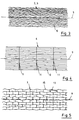
- Figures 2 to 5 show on an enlarged scale and in plan views a carbon fiber fabric (Fig. 2), a carbon fiber cable (Fig. 3), a Kolhemaschineband (Fig. 4) and a honeycomb material (Fig. 5) in this order.
- the tube consists of an inner jacket, a middle layer of honeycomb material and an outer jacket.
- the inner jacket consists of a carbon fiber fabric 1, over which there are carbon fiber cables 2 (see FIG. 1).
- the middle layer consists of a honeycomb material 3 made of a suitable paper material, which is optionally lacquered or impregnated with synthetic resin. This is a commercial product.
- the outer jacket consists of a carbon fiber fabric 4, which basically corresponds to the carbon fiber fabric 1.
- a carbon fiber cable 5 corresponding to the carbon fiber cable 2 and the outside of the tube is covered by a carbon fiber tape 6. This preferably runs spirally around the pipe.
- the inner jacket consisting of layers 1, 2 is impregnated with synthetic resin and the same applies to the outer jacket consisting of layers 4, 5, 6.
- the described tube is preferably used as a deflection shaft or expansion shaft.
Landscapes
- Engineering & Computer Science (AREA)
- Mechanical Engineering (AREA)
- General Engineering & Computer Science (AREA)
- Laminated Bodies (AREA)
- Shafts, Cranks, Connecting Bars, And Related Bearings (AREA)
- Golf Clubs (AREA)
Description
- Die Erfindung betrifft ein Rohr, insbesondere für eine Umlenkwelle, Expansionswelle und dergleichen, mit den Merkmalen des Oberbegriffs von Anspruch 1.
- Umlenkwellen werden in der Bahnen verarbeitenden Industrie eingesetzt, wo sie zum Umlenken der in der betreffenden Maschine verarbeiteten Bahnen dienen. Sie bestehen üblicherweise aus Stahlrohren. Dasselbe gilt für Expansionswellen, auch Spannwellen genannt, die zum Spannvorgang ihren Durchmesser ändern können. Derartige Expansionswellen aus Stahl sind beispielsweise in der DE-U-86 34 752 beschrieben.
- Nachteilig bei den bekannten Rohren bzw. Wellen aus Stahl ist insbesondere ihr sehr hohes Gewicht. Beispielsweise wiegt eine acht Meter lange Umlenkwelle mit einem Durchmesser von 300 mm aus Stahlrohr etwa 1,25 t.
- Es sind auch schon Rohre aus einem massiven kunstharzgetränkten Kohlefasergewebe bekannt, die aber ebenfalls verhältnismäßig schwer sind, wenn das Rohr allen mechanischen Anforderungen genügen soll.
- Ein Leichtbaurohr mit den Merkmalen des Oberbegriffs von Anspruch 1 ist in der GB-A-1 480 928 beschrieben. Der Innenmantel besteht dort aus Fasergewebe und der Außenmantel aus einem Faserband bzw. Fasergewebe. Dieses bekannte Rohr dürfte in der Praxis aber immer noch nicht allen Beanspruchungen standhalten, insbesondere nicht allen Biegebeanspruchungen.
- Der Erfindung liegt daher die Aufgabe zugrunde, ein Rohr, insbesondere eine Umlenkwelle oder eine Expansionswelle vorzuschlagen, das allen an die Welle im Betrieb gestellten Anforderungen genügt, insbesondere in Bezug auf seine Biegesteifigkeit, und das sich durch ein fühlbar verringertes Gewicht auszeichnen soll.
- Die Lösung dieser Aufgabe gelingt durch die Merkmale des Anspruchs 1.
- Der Innenmantel und der Außenmantel aus dem kunstharzgetränkten Gewebe wird man je nach den Anforderungen aufbauen.
- Das Fasergewebe des Innenmantels sorgt für eine glatte Fläche beim Herstellen des Rohres, so daß dieses, ggfs. mit Hilfe eines geeigneten Trennmittels, leicht von einem Grundrohr abgezogen werden kann, auf dem das erfindungsgemäße Rohr hergestellt wird. Außerdem liefert das Fasergewebe den notwendigen Grundaufbau für die darauf aufgebrachten Faserkabel. Unter einem Faserkabel versteht man im Sinne der Erfindung eine Vielzahl von sich in axialer Richtung erstreckenden Fasern. Diese sorgen vor allem für die angestrebte hohe Biegesteifigkeit des Rohres.
- Das Fasergewebe des Außenmantels deckt das Wabenmaterial ab und sorgt dafür, daß kein flüssiges Kunstharz in die Waben eindringt. Es liefert außerdem den notwendigen Aufbau für die darüber befindliche Schicht der Faserkabel, die sich auch hier im wesentlichen in Längsrichtung (Axialrichtung) des Rohres erstrecken und die wesentlich zur angestrebten hohen Biegesteifigkeit des Rohres beitragen. Der Aufbau wird nach außen von dem Faserband abgeschlossen mit dem Vliesstoff als Decklage, das die notwendige glatte Außenfläche des Rohres ergibt.
- Durch die erfindungsgemäße Sandwichbauweise erhält man überraschend stabile und gleichzeitig leichte Rohre. Beispielsweise wiegt ein acht Meter langes Rohr mit einem Durchmesser von 300 mm, welches dieselben mechanischen Eigenschaften hat wie das eingangs erwähnte Rohr mit diesen bemessungen aus Stahl nur etwa 100 kg, d.h. weniger als ein Zehntel als ein vergleichbares Stahlrohr. Die mit einem derart leichtgewichtigen Rohr einhergehenden Vorteile liegen auf der Hand. Beispielsweise müssen nur entsprechend geringere Massen gelagert, beschleunigt und abgebremst werden und auch die Handhabung und der Transport sind fühlbar erleichtert. Es entsteht auch im Betrieb als Umlenkwelle keine statische Aufladung der betreffenden Warenbahn mehr, da kein Schlupf besteht. Die Handhabung und der Transport sind fühlbar erleichtert.
- Für das Wabenmaterial wird man eine Wabenstruktur aus Papiermaterial oder Kunststoff verwenden, wie sie handelsüblich ist. Der Kunstharz verbindet den Sandwichaufbau untrennbar zu einem einstückigen Rohr. Das Wabenmaterial dient im Sandwichaufbau auch als Abstandshalter und ist auch aus statischen Gründen vorgesehen.
- Auch bezüglich des Aufbaus des Außenmantels gilt das vorstehend zum Innenmantel Gesagte, d.h. daß das Fasergewebe vorzugsweise nach Art eines Strumpfes ausgebildet ist mit sich spitzwinklig kreuzenden Strängen aus den Fasern. Das Faserkabel besteht im wesentlichen aus einer Vielzahl von sich in axialer Richtung erstreckenden und rings um das Rohr angeordneten, zueinander im wesentlichen parallelen und nur gering miteinander verzwirnten Fasern. Das Faserband schließlich besteht ebenfalls aus sich im wesentlichen in axialer Richtung erstreckenden Fasern, die aber durch Querfäden zu einem flachen, leicht handhabbaren Band miteinander verbunden sind. Das Faserband muß sich nicht in axialer Richtung erstrecken, sondern kann beispielsweise auch spiralig aufgewickelt sien.
- Allgemein sei erläutert, daß der Aufbau des Innenmantels und/oder des Außenmantels nicht aus reinen Kohlefasern bestehen muß. Kohlefasern oder Aramidfasern sollen aber überwiegen. Es können andere Fasern beigemischt sein, beispielsweise Glasfasern.
- Die Erfindung wird im folgenden anhand eines Ausführungsbeispiels näher erläutert, aus dem sich weitere wichtige Merkmale ergeben. Dabei wird als Beispiel von Kohlefasern gesprochen. Statt dessen oder zusätzlich können aber auch Aramidfasern vorgesehen sein oder auch Fasern aus anderen Materialien, die den notwendigen Anforderungen, insbesondere an die Zugfestigkeit, genügen.
- Figur 1 zeigt schematisch in einer Stirnansicht ein erfindungsgemäßes Rohr, wobei zur Verdeutlichung der Aufbau des Rohres in der Einzelheit X vergrößert herausgezeichnet ist.
- Die Figuren 2 bis 5 zeigen in vergrößertem Maßstab und in Draufsichten eine Kohlefasergewebe (Fig. 2), ein Kohlefaserkabel (Fig. 3) ein Kolhefaserband (Fig. 4) und ein Wabenmaterial (Fig. 5) in dieser Reihenfolge.
- Das Rohr besteht aus einem Innenmantel, einer Mittelschicht aus Wabenmaterial und einem Außenmantel. Der Innenmantel besteht aus einem Kohlefasergewebe 1, über dem sich Kohlefaserkabel 2 befinden (Vgl. Fig. 1)
- Die Mittelschicht besteht aus einem Wabenmaterial 3 aus geeignetem Papiermaterial, welches gegebenenfalls lackiert oder kunstharzgetränkt ist. Dies ist ein handelsübliches Produkt.
- Der Außenmantel besteht aus einem Kohlefasergewebe 4, das grundsätzlich dem Kohlefasergewebe 1 entspricht. Darüber befindet sich ein Kohlefaserkabel 5 entsprechend dem Kohlefaserkabel 2 und nach außen ist das Rohr von einem Kohlefaserband 6 abgedeckt. Dies verläuft vorzugsweise spiralig um das Rohr.
- Der aus den Schichten 1, 2 bestehende Innenmantel ist kunstharzgetränkt und dasselbe gilt für den Außenmantel, der aus den Schichten 4, 5, 6 besteht.
- Die Mittelschicht braucht nicht aus Papiermaterial zu bestehen. Für sie kann vielmehr jedes geeignete Material in Wabenform verwendet werden. Die die Waben ausbildenden Wände verlaufen in radialer Richtung.
- Fig. 2 zeigt eine Ansicht des flach gelegten Kohlefasergewebes 1, 4 aus der auch die sich spitzwinklig kreuzenden Stränge 7, 8 aus Kohlefasern ersichtlich sind. Die Achse des Rohres nach Fig. 1 ist bei Pos. 9 angedeutet.
- Fig. 3 zeigt ebenfalls flach gelegt das Kohlefaserkabel 2, 5, das aus einer Vielzahl von sich in axialer Richtung 9 erstreckenden, zueinander im wesentlichen parallelen und nur gering miteinander verzwirnten Kohlfasern 10 besteht.
- Fig. 4 zeigt das - ebenfalls flach gelegte - Kohlefaserband 6, bei dem die Kohlefasern 10 durch Querfäden 11 zu einem Band miteinander verbunden sind.
- Fig. 5 zeigt das ebenfalls flach gelegte Wabenmaterial 3 mit Längsstegen 12, die über auf Lücke gesetzte Querstege 13 miteinander verbunden sind. In Wirklichkeit wird das Wabenmaterial durch sich in Querrichtung erstreckende, wellenförmige Bänder gebildet, die an den Basen ihrer U-Profile jeweils miteinander verklebt sind. Die doppelt gelegten Basen bilden die Querstege 13 aus und die Schenkel der U-Profile die Längsstege 12.
- Das beschriebene Rohr dient nach entsprechender Komplettierung vorzugsweise als Umlenkwelle oder Expansionswelle.
Claims (3)
dadurch gekennzeichnet,
daß der Innenmantel aus dem Fasergewebe (1), einem Faservlies oder einem Fasergelege besteht, auf dessen Außenseite ein Faserkabel (2) aufgebracht ist, und daß der Außenmantel von innen nach außen aus dem Fasergewebe (4), einem Faserkabel (5) und dem Faserband (6) besteht.
dadurch gekennzeichnet,
daß das Wabenmaterial (3) aus Papiermaterial oder Kunststoff besteht.
dadurch gekennzeichnet,
daß die Bestandteile (1,2) des Innenmantels und/oder die Bestandteile (4,5,6) des Außenmantels zumindest überwiegend aus Kohlefasern und/oder Aramidfasern bestehen.
Priority Applications (1)
| Application Number | Priority Date | Filing Date | Title |
|---|---|---|---|
| AT89113332T ATE74189T1 (de) | 1989-06-15 | 1989-07-20 | Rohr, insbesondere fuer eine umlenkwelle, expansionswelle oder dergleichen. |
Applications Claiming Priority (2)
| Application Number | Priority Date | Filing Date | Title |
|---|---|---|---|
| DE8907321U DE8907321U1 (de) | 1989-06-15 | 1989-06-15 | Rohr, insbesondere Umlenkwelle, Expansionswelle o.dgl. |
| DE8907321U | 1989-06-15 |
Publications (2)
| Publication Number | Publication Date |
|---|---|
| EP0403686A1 EP0403686A1 (de) | 1990-12-27 |
| EP0403686B1 true EP0403686B1 (de) | 1992-03-25 |
Family
ID=6840127
Family Applications (2)
| Application Number | Title | Priority Date | Filing Date |
|---|---|---|---|
| EP89113332A Expired - Lifetime EP0403686B1 (de) | 1989-06-15 | 1989-07-20 | Rohr, insbesondere für eine Umlenkwelle, Expansionswelle oder dergleichen |
| EP89113331A Expired - Lifetime EP0403685B1 (de) | 1989-06-15 | 1989-07-20 | Verfahren zur Herstellung eines Rohrkörpers einer Expansionswelle |
Family Applications After (1)
| Application Number | Title | Priority Date | Filing Date |
|---|---|---|---|
| EP89113331A Expired - Lifetime EP0403685B1 (de) | 1989-06-15 | 1989-07-20 | Verfahren zur Herstellung eines Rohrkörpers einer Expansionswelle |
Country Status (5)
| Country | Link |
|---|---|
| US (2) | US5151144A (de) |
| EP (2) | EP0403686B1 (de) |
| AT (2) | ATE85770T1 (de) |
| CA (2) | CA2019031A1 (de) |
| DE (3) | DE8907321U1 (de) |
Families Citing this family (17)
| Publication number | Priority date | Publication date | Assignee | Title |
|---|---|---|---|---|
| JPH04113832A (ja) * | 1990-09-04 | 1992-04-15 | Mitsubishi Rayon Co Ltd | ハニカムコアーの構造 |
| FR2683260B1 (fr) * | 1991-11-05 | 1995-10-20 | Aerospatiale | Tube en materiau composite pour forage et/ou transport de produits liquides ou gazeux, en particulier pour l'exploitation petroliere en mer et procede de fabrication d'un tel tube. |
| US5351752A (en) * | 1992-06-30 | 1994-10-04 | Exoko, Incorporated (Wood) | Artificial lifting system |
| WO1995025633A1 (en) * | 1994-03-24 | 1995-09-28 | Toray Industries, Inc. | Bent tube, method of and apparatus for manufacturing same |
| CN1058329C (zh) * | 1997-01-23 | 2000-11-08 | 张国祥 | 加筋耐压塑料管及管连接件 |
| RU2174467C2 (ru) * | 1999-04-27 | 2001-10-10 | Открытое акционерное общество Научно-производственное объединение "Композит" | Способ изготовления оболочки и ее конструкция |
| FR2821788B1 (fr) * | 2001-03-09 | 2004-04-02 | Eads Airbus Sa | Procede de fabrication d'un panneau a couche resistive acoustique adaptee et panneau acoustique ainsi obtenu |
| ITPD20010064A1 (it) * | 2001-03-16 | 2002-09-16 | Vittorio Pareti | Struttura portante per la realizzazione di opere edili |
| US20030114232A1 (en) * | 2001-12-14 | 2003-06-19 | Visteon Global Technologies, Inc. | Enhanced strength composite drive shaft |
| US7815160B2 (en) * | 2006-04-04 | 2010-10-19 | A & P Technology | Composite mandrel |
| US20080017020A1 (en) * | 2006-07-18 | 2008-01-24 | Sonoco Development, Inc. | Rapidly Deployable Barrier for High-Speed Projectiles |
| DE102008016462A1 (de) * | 2008-03-31 | 2009-10-01 | Airbus Deutschland Gmbh | Verbessertes Klimarohr, insbesondere für Flugzeuge |
| DE102010015108A1 (de) | 2010-04-16 | 2011-10-20 | Goebel Gmbh | Rotationszylinder für eine Verarbeitungsmaschine |
| GB2481058A (en) * | 2010-06-11 | 2011-12-14 | Composite Core Technologies Ltd | Three layered web-winding core |
| LU91741B1 (de) | 2010-09-24 | 2012-03-26 | Euro Composites | Mehrschichtige expandierbare Hülse für einen Druckmaschinenzylinder insbesondere für Flexodruck |
| CN102062265A (zh) * | 2010-12-10 | 2011-05-18 | 上海意耐玻璃钢有限公司 | 一种管壁中空增强结构玻璃钢管道 |
| CN115051306B (zh) * | 2022-06-07 | 2024-06-25 | 青岛中集创赢复合材料科技有限公司 | 一种电缆护套管及其制备方法 |
Family Cites Families (28)
| Publication number | Priority date | Publication date | Assignee | Title |
|---|---|---|---|---|
| US3013584A (en) * | 1955-03-28 | 1961-12-19 | Gar Wood Ind Inc | Supporting members |
| US2878038A (en) * | 1955-06-27 | 1959-03-17 | Reinhold Engineering & Plastic | Plastic pipe bend and method for making same |
| DE1159698B (de) * | 1960-08-20 | 1963-12-19 | Aerojet General Co | Durchbrochener Kunststoffbehaelter, insbesondere Zuendbehaelter fuer fluessige oder feste Raketentreibstoffe und Verfahren zur Herstellung des Behaelters |
| US3145000A (en) * | 1963-05-29 | 1964-08-18 | William L Mackie | Light weight-high thermal resistant airfoil |
| US3259961A (en) * | 1964-12-21 | 1966-07-12 | Metal Tech Inc | Cylindrical honeycomb roll |
| US3490983A (en) * | 1965-05-17 | 1970-01-20 | Hitco | Fiber reinforced structures and methods of making the same |
| DE6750615U (de) * | 1968-09-30 | 1969-01-09 | Mancar Trust | Mehrschichtiges glasfaserverstaerktes kunststoffrohr |
| BE755780A (fr) * | 1969-09-12 | 1971-02-15 | Basler Stueckfaerberei Ag | Tuyau flexible en matiere synthetique renforce par des fibres et procede pour le fabriquer |
| US3853600A (en) * | 1971-05-12 | 1974-12-10 | Celanese Corp | Improved carbon fiber reinforced composite article |
| US3765980A (en) * | 1971-09-24 | 1973-10-16 | Combination Eng Inc | Method for forming pipe with integral hole or nozzle pattern |
| US4025675A (en) * | 1973-12-19 | 1977-05-24 | Messerschmitt-Bolkow-Blohm Gmbh | Reinforced laminates |
| DD124788A1 (de) * | 1976-04-05 | 1977-03-16 | ||
| US4563321A (en) * | 1977-10-13 | 1986-01-07 | Gessford James D | Method of producing a plastic unitary curved structure with two surfaces and a honeycomb shaped core |
| US4248062A (en) * | 1979-10-05 | 1981-02-03 | Shakespeare Company | Drive shaft assembly and method for making same |
| US4565595A (en) * | 1981-09-30 | 1986-01-21 | The Boeing Company | Method of making composite aircraft wing |
| US4787583A (en) * | 1982-10-12 | 1988-11-29 | Conoco Inc. | Clamp for arctic pipeline support |
| DE3246755A1 (de) * | 1982-12-17 | 1984-06-20 | Richard 4937 Lage Pott | Verfahren zur herstellung eines formkoerpers aus verbundmaterial und nach diesem verfahren hergestellter formkoerper |
| GB8306653D0 (en) * | 1983-03-10 | 1983-04-13 | Secr Defence | Fibre reinforced composites |
| FR2546473B1 (fr) * | 1983-05-24 | 1987-12-11 | Verre Tisse Sa | Materiau tubulaire a base d'une resine renforcee par une matiere textile et cadre de bicyclette ou vehicule similaire realise a partir d'un tel materiau |
| DE8322639U1 (de) * | 1983-08-05 | 1983-12-01 | Uranit GmbH, 5170 Jülich | Leitwalzen für Papier-, Folienveredelungs- und Druckmaschinen |
| US4600619A (en) * | 1984-12-31 | 1986-07-15 | The Boeing Company | Continuously wound filament structure for use in noise attenuation element |
| US4786536A (en) * | 1985-03-27 | 1988-11-22 | Kaempen Charles E | Composite deflectable spring structure |
| JPS62257835A (ja) * | 1986-05-06 | 1987-11-10 | Mitsubishi Electric Corp | サンドイツチ構造体およびその製造方法 |
| DE8634752U1 (de) * | 1986-12-27 | 1987-02-26 | Tidland Gmbh, 4422 Ahaus | Spannwelle |
| DE8708474U1 (de) * | 1987-06-16 | 1987-12-03 | Integrated Materials Technology GmbH, 65760 Eschborn | Leichtlaufwalze mit einem Walzenrohr in Schichtenbauart |
| GB8717130D0 (en) * | 1987-07-20 | 1987-08-26 | Francais Isolants | Braided composite article |
| DE3733731A1 (de) * | 1987-10-06 | 1989-04-27 | Messerschmitt Boelkow Blohm | Antriebswelle |
| CH673878A5 (de) * | 1987-10-28 | 1990-04-12 | Benninger Ag Maschf |
-
1989
- 1989-06-15 DE DE8907321U patent/DE8907321U1/de not_active Expired - Lifetime
- 1989-07-20 EP EP89113332A patent/EP0403686B1/de not_active Expired - Lifetime
- 1989-07-20 AT AT89113331T patent/ATE85770T1/de not_active IP Right Cessation
- 1989-07-20 AT AT89113332T patent/ATE74189T1/de active
- 1989-07-20 DE DE8989113331T patent/DE58903576D1/de not_active Expired - Fee Related
- 1989-07-20 DE DE8989113332T patent/DE58901048D1/de not_active Expired - Lifetime
- 1989-07-20 EP EP89113331A patent/EP0403685B1/de not_active Expired - Lifetime
-
1990
- 1990-06-13 US US07/537,511 patent/US5151144A/en not_active Expired - Fee Related
- 1990-06-13 US US07/537,420 patent/US5080943A/en not_active Expired - Fee Related
- 1990-06-14 CA CA002019031A patent/CA2019031A1/en not_active Abandoned
- 1990-06-14 CA CA002019032A patent/CA2019032A1/en not_active Abandoned
Also Published As
| Publication number | Publication date |
|---|---|
| DE8907321U1 (de) | 1991-03-28 |
| EP0403685B1 (de) | 1993-02-17 |
| ATE85770T1 (de) | 1993-03-15 |
| CA2019032A1 (en) | 1990-12-15 |
| DE58901048D1 (de) | 1992-04-30 |
| EP0403685A1 (de) | 1990-12-27 |
| DE58903576D1 (de) | 1993-03-25 |
| ATE74189T1 (de) | 1992-04-15 |
| US5080943A (en) | 1992-01-14 |
| CA2019031A1 (en) | 1990-12-15 |
| US5151144A (en) | 1992-09-29 |
| EP0403686A1 (de) | 1990-12-27 |
Similar Documents
| Publication | Publication Date | Title |
|---|---|---|
| EP0403686B1 (de) | Rohr, insbesondere für eine Umlenkwelle, Expansionswelle oder dergleichen | |
| EP1025996B1 (de) | Druckplattenzylinder | |
| DE10108357A1 (de) | Armierungsstab sowie Verfahren zu dessen Herstellung | |
| DE3246755A1 (de) | Verfahren zur herstellung eines formkoerpers aus verbundmaterial und nach diesem verfahren hergestellter formkoerper | |
| DE2710275B2 (de) | Stange zur Übertragung von Kräften | |
| EP2141010B1 (de) | Kaskadenführung | |
| EP0225485B1 (de) | Blattfeder aus Faser-Kunststoff-Verbundwerkstoff | |
| DE3703564A1 (de) | Streckwalze oder aehnliche walze fuer papiermaschinentuecher sowie ein verfahren zur herstellung der walze | |
| DE202019006120U1 (de) | Ummanteltes Rohr und Rohrverbindung, Rohrverbund und Gleitkufen | |
| DE19511153C2 (de) | Kalanderwalze, insbesondere für die Papierbehandlung | |
| DE69600470T2 (de) | Versteifungsstruktur für Hohlwellen zum Wickeln von Materialbahnen | |
| DE29613795U1 (de) | Walze mit optimiertem Biegeverhalten | |
| DE1753803C3 (de) | Verfahren zum Herstellen eines in Längsrichtung und im wesentlichen in Umfangsrichtung verstärkten Kunststoffrohres | |
| DE3107838C2 (de) | Verfahren zur Herstellung von Doppelmantel-Kunststoffrohren | |
| EP0879330B1 (de) | Hohlprofilförmiges tragelement für die bautechnik | |
| EP0876898B1 (de) | Vorrichtung zur Herstellung eines Relining-Schlauchs | |
| DE19533501C1 (de) | Hohlprofilförmiges Tragelement für die Bautechnik | |
| DE3714112C2 (de) | ||
| DE102014105795A1 (de) | Textiles Flächengebilde | |
| DE2828061A1 (de) | Verfahren zum verpacken von glasfaserspinnkuchen | |
| DE2007455C (de) | ||
| DE1273478B (de) | Verfahren und Maschine zur Herstellung eines nicht gewebten gitterartigen Fadengeleges, insbesondere zur Verstaerkung von flaechigen Verbundmaterialien | |
| EP0385948A1 (de) | Walze zur Druckbehandlung von bahnförmigen Materialien, Verwendung eines bandförmigen Flächengebildes zum Herstellen eines Trägerrohrs und Verwendung eines Trägerrohrs aus faserverstärktem Kunststoff | |
| DE19613699C1 (de) | Hohlprofilförmiges Tragelement für die Bautechnik | |
| DE4107308A1 (de) | Walze fuer eine pressenpartie einer papiermaschine |
Legal Events
| Date | Code | Title | Description |
|---|---|---|---|
| PUAI | Public reference made under article 153(3) epc to a published international application that has entered the european phase |
Free format text: ORIGINAL CODE: 0009012 |
|
| 17P | Request for examination filed |
Effective date: 19900625 |
|
| AK | Designated contracting states |
Kind code of ref document: A1 Designated state(s): AT BE CH DE ES FR GB GR IT LI LU NL SE |
|
| 17Q | First examination report despatched |
Effective date: 19910613 |
|
| GRAA | (expected) grant |
Free format text: ORIGINAL CODE: 0009210 |
|
| AK | Designated contracting states |
Kind code of ref document: B1 Designated state(s): AT BE CH DE ES FR GB GR IT LI LU NL SE |
|
| PG25 | Lapsed in a contracting state [announced via postgrant information from national office to epo] |
Ref country code: SE Effective date: 19920325 Ref country code: NL Effective date: 19920325 Ref country code: GR Free format text: LAPSE BECAUSE OF FAILURE TO SUBMIT A TRANSLATION OF THE DESCRIPTION OR TO PAY THE FEE WITHIN THE PRESCRIBED TIME-LIMIT Effective date: 19920325 Ref country code: ES Free format text: THE PATENT HAS BEEN ANNULLED BY A DECISION OF A NATIONAL AUTHORITY Effective date: 19920325 |
|
| REF | Corresponds to: |
Ref document number: 74189 Country of ref document: AT Date of ref document: 19920415 Kind code of ref document: T |
|
| REF | Corresponds to: |
Ref document number: 58901048 Country of ref document: DE Date of ref document: 19920430 |
|
| GBT | Gb: translation of ep patent filed (gb section 77(6)(a)/1977) | ||
| ITF | It: translation for a ep patent filed | ||
| REG | Reference to a national code |
Ref country code: CH Ref legal event code: PUE Owner name: CHRISTIAN CHLUPSA |
|
| ET | Fr: translation filed | ||
| NLV1 | Nl: lapsed or annulled due to failure to fulfill the requirements of art. 29p and 29m of the patents act | ||
| ITPR | It: changes in ownership of a european patent |
Owner name: CESSIONE;CHRISTIAN CHLUPSA |
|
| BECH | Be: change of holder |
Free format text: 920714 *CHLUPSA CHRISTIAN;*VETTER WALTER |
|
| PLBE | No opposition filed within time limit |
Free format text: ORIGINAL CODE: 0009261 |
|
| STAA | Information on the status of an ep patent application or granted ep patent |
Free format text: STATUS: NO OPPOSITION FILED WITHIN TIME LIMIT |
|
| 26N | No opposition filed | ||
| REG | Reference to a national code |
Ref country code: GB Ref legal event code: 732E |
|
| EPTA | Lu: last paid annual fee | ||
| PGFP | Annual fee paid to national office [announced via postgrant information from national office to epo] |
Ref country code: FR Payment date: 19970506 Year of fee payment: 9 |
|
| PGFP | Annual fee paid to national office [announced via postgrant information from national office to epo] |
Ref country code: CH Payment date: 19970526 Year of fee payment: 9 |
|
| PGFP | Annual fee paid to national office [announced via postgrant information from national office to epo] |
Ref country code: BE Payment date: 19970529 Year of fee payment: 9 |
|
| PGFP | Annual fee paid to national office [announced via postgrant information from national office to epo] |
Ref country code: GB Payment date: 19970604 Year of fee payment: 9 Ref country code: AT Payment date: 19970604 Year of fee payment: 9 |
|
| PGFP | Annual fee paid to national office [announced via postgrant information from national office to epo] |
Ref country code: LU Payment date: 19970605 Year of fee payment: 9 |
|
| PGFP | Annual fee paid to national office [announced via postgrant information from national office to epo] |
Ref country code: DE Payment date: 19970723 Year of fee payment: 9 |
|
| PG25 | Lapsed in a contracting state [announced via postgrant information from national office to epo] |
Ref country code: LU Free format text: LAPSE BECAUSE OF NON-PAYMENT OF DUE FEES Effective date: 19980720 Ref country code: GB Free format text: LAPSE BECAUSE OF NON-PAYMENT OF DUE FEES Effective date: 19980720 Ref country code: AT Free format text: LAPSE BECAUSE OF NON-PAYMENT OF DUE FEES Effective date: 19980720 |
|
| PG25 | Lapsed in a contracting state [announced via postgrant information from national office to epo] |
Ref country code: LI Free format text: LAPSE BECAUSE OF NON-PAYMENT OF DUE FEES Effective date: 19980731 Ref country code: CH Free format text: LAPSE BECAUSE OF NON-PAYMENT OF DUE FEES Effective date: 19980731 Ref country code: BE Free format text: LAPSE BECAUSE OF NON-PAYMENT OF DUE FEES Effective date: 19980731 |
|
| BERE | Be: lapsed |
Owner name: VETTER WALTER Effective date: 19980731 Owner name: CHLUPSA CHRISTIAN Effective date: 19980731 |
|
| GBPC | Gb: european patent ceased through non-payment of renewal fee |
Effective date: 19980720 |
|
| REG | Reference to a national code |
Ref country code: CH Ref legal event code: PL |
|
| PG25 | Lapsed in a contracting state [announced via postgrant information from national office to epo] |
Ref country code: FR Free format text: LAPSE BECAUSE OF NON-PAYMENT OF DUE FEES Effective date: 19990331 |
|
| PG25 | Lapsed in a contracting state [announced via postgrant information from national office to epo] |
Ref country code: DE Free format text: LAPSE BECAUSE OF NON-PAYMENT OF DUE FEES Effective date: 19990501 |
|
| REG | Reference to a national code |
Ref country code: FR Ref legal event code: ST |
|
| PG25 | Lapsed in a contracting state [announced via postgrant information from national office to epo] |
Ref country code: IT Free format text: LAPSE BECAUSE OF NON-PAYMENT OF DUE FEES;WARNING: LAPSES OF ITALIAN PATENTS WITH EFFECTIVE DATE BEFORE 2007 MAY HAVE OCCURRED AT ANY TIME BEFORE 2007. THE CORRECT EFFECTIVE DATE MAY BE DIFFERENT FROM THE ONE RECORDED. Effective date: 20050720 |