EP0403239B1 - Verdichteranlage mit steuerbarer Leistung - Google Patents
Verdichteranlage mit steuerbarer Leistung Download PDFInfo
- Publication number
- EP0403239B1 EP0403239B1 EP90306416A EP90306416A EP0403239B1 EP 0403239 B1 EP0403239 B1 EP 0403239B1 EP 90306416 A EP90306416 A EP 90306416A EP 90306416 A EP90306416 A EP 90306416A EP 0403239 B1 EP0403239 B1 EP 0403239B1
- Authority
- EP
- European Patent Office
- Prior art keywords
- compressors
- compressor
- oil
- lubricating oil
- pipe
- Prior art date
- Legal status (The legal status is an assumption and is not a legal conclusion. Google has not performed a legal analysis and makes no representation as to the accuracy of the status listed.)
- Expired - Lifetime
Links
- 239000003921 oil Substances 0.000 claims description 134
- 239000010687 lubricating oil Substances 0.000 claims description 105
- 239000003507 refrigerant Substances 0.000 claims description 59
- 230000006835 compression Effects 0.000 claims description 17
- 238000007906 compression Methods 0.000 claims description 17
- 238000011144 upstream manufacturing Methods 0.000 claims description 17
- 230000006837 decompression Effects 0.000 claims description 13
- 230000000694 effects Effects 0.000 claims description 11
- 238000004891 communication Methods 0.000 description 12
- 238000005187 foaming Methods 0.000 description 10
- 239000007788 liquid Substances 0.000 description 10
- 230000004048 modification Effects 0.000 description 9
- 238000012986 modification Methods 0.000 description 9
- 238000009828 non-uniform distribution Methods 0.000 description 9
- 238000010276 construction Methods 0.000 description 4
- 238000004378 air conditioning Methods 0.000 description 3
- 238000010586 diagram Methods 0.000 description 3
- 238000001816 cooling Methods 0.000 description 2
- 230000003247 decreasing effect Effects 0.000 description 2
- 238000010790 dilution Methods 0.000 description 2
- 239000012895 dilution Substances 0.000 description 2
- 238000007710 freezing Methods 0.000 description 2
- 230000008014 freezing Effects 0.000 description 2
- 230000001419 dependent effect Effects 0.000 description 1
- 238000009826 distribution Methods 0.000 description 1
- 239000000314 lubricant Substances 0.000 description 1
- 238000004519 manufacturing process Methods 0.000 description 1
- 238000000034 method Methods 0.000 description 1
Images


Classifications
-
- F—MECHANICAL ENGINEERING; LIGHTING; HEATING; WEAPONS; BLASTING
- F16—ENGINEERING ELEMENTS AND UNITS; GENERAL MEASURES FOR PRODUCING AND MAINTAINING EFFECTIVE FUNCTIONING OF MACHINES OR INSTALLATIONS; THERMAL INSULATION IN GENERAL
- F16N—LUBRICATING
- F16N19/00—Lubricant containers for use in lubricators or lubrication systems
- F16N19/006—Maintaining oil level
-
- F—MECHANICAL ENGINEERING; LIGHTING; HEATING; WEAPONS; BLASTING
- F04—POSITIVE - DISPLACEMENT MACHINES FOR LIQUIDS; PUMPS FOR LIQUIDS OR ELASTIC FLUIDS
- F04B—POSITIVE-DISPLACEMENT MACHINES FOR LIQUIDS; PUMPS
- F04B41/00—Pumping installations or systems specially adapted for elastic fluids
- F04B41/06—Combinations of two or more pumps
-
- F—MECHANICAL ENGINEERING; LIGHTING; HEATING; WEAPONS; BLASTING
- F04—POSITIVE - DISPLACEMENT MACHINES FOR LIQUIDS; PUMPS FOR LIQUIDS OR ELASTIC FLUIDS
- F04B—POSITIVE-DISPLACEMENT MACHINES FOR LIQUIDS; PUMPS
- F04B39/00—Component parts, details, or accessories, of pumps or pumping systems specially adapted for elastic fluids, not otherwise provided for in, or of interest apart from, groups F04B25/00 - F04B37/00
- F04B39/02—Lubrication
- F04B39/0207—Lubrication with lubrication control systems
-
- F—MECHANICAL ENGINEERING; LIGHTING; HEATING; WEAPONS; BLASTING
- F25—REFRIGERATION OR COOLING; COMBINED HEATING AND REFRIGERATION SYSTEMS; HEAT PUMP SYSTEMS; MANUFACTURE OR STORAGE OF ICE; LIQUEFACTION SOLIDIFICATION OF GASES
- F25B—REFRIGERATION MACHINES, PLANTS OR SYSTEMS; COMBINED HEATING AND REFRIGERATION SYSTEMS; HEAT PUMP SYSTEMS
- F25B31/00—Compressor arrangements
- F25B31/002—Lubrication
-
- F—MECHANICAL ENGINEERING; LIGHTING; HEATING; WEAPONS; BLASTING
- F25—REFRIGERATION OR COOLING; COMBINED HEATING AND REFRIGERATION SYSTEMS; HEAT PUMP SYSTEMS; MANUFACTURE OR STORAGE OF ICE; LIQUEFACTION SOLIDIFICATION OF GASES
- F25B—REFRIGERATION MACHINES, PLANTS OR SYSTEMS; COMBINED HEATING AND REFRIGERATION SYSTEMS; HEAT PUMP SYSTEMS
- F25B2400/00—General features or devices for refrigeration machines, plants or systems, combined heating and refrigeration systems or heat-pump systems, i.e. not limited to a particular subgroup of F25B
- F25B2400/07—Details of compressors or related parts
- F25B2400/075—Details of compressors or related parts with parallel compressors
-
- F—MECHANICAL ENGINEERING; LIGHTING; HEATING; WEAPONS; BLASTING
- F25—REFRIGERATION OR COOLING; COMBINED HEATING AND REFRIGERATION SYSTEMS; HEAT PUMP SYSTEMS; MANUFACTURE OR STORAGE OF ICE; LIQUEFACTION SOLIDIFICATION OF GASES
- F25B—REFRIGERATION MACHINES, PLANTS OR SYSTEMS; COMBINED HEATING AND REFRIGERATION SYSTEMS; HEAT PUMP SYSTEMS
- F25B2600/00—Control issues
- F25B2600/02—Compressor control
- F25B2600/025—Compressor control by controlling speed
- F25B2600/0253—Compressor control by controlling speed with variable speed
-
- F—MECHANICAL ENGINEERING; LIGHTING; HEATING; WEAPONS; BLASTING
- F25—REFRIGERATION OR COOLING; COMBINED HEATING AND REFRIGERATION SYSTEMS; HEAT PUMP SYSTEMS; MANUFACTURE OR STORAGE OF ICE; LIQUEFACTION SOLIDIFICATION OF GASES
- F25B—REFRIGERATION MACHINES, PLANTS OR SYSTEMS; COMBINED HEATING AND REFRIGERATION SYSTEMS; HEAT PUMP SYSTEMS
- F25B31/00—Compressor arrangements
- F25B31/002—Lubrication
- F25B31/004—Lubrication oil recirculating arrangements
-
- F—MECHANICAL ENGINEERING; LIGHTING; HEATING; WEAPONS; BLASTING
- F25—REFRIGERATION OR COOLING; COMBINED HEATING AND REFRIGERATION SYSTEMS; HEAT PUMP SYSTEMS; MANUFACTURE OR STORAGE OF ICE; LIQUEFACTION SOLIDIFICATION OF GASES
- F25B—REFRIGERATION MACHINES, PLANTS OR SYSTEMS; COMBINED HEATING AND REFRIGERATION SYSTEMS; HEAT PUMP SYSTEMS
- F25B5/00—Compression machines, plants or systems, with several evaporator circuits, e.g. for varying refrigerating capacity
- F25B5/02—Compression machines, plants or systems, with several evaporator circuits, e.g. for varying refrigerating capacity arranged in parallel
-
- Y—GENERAL TAGGING OF NEW TECHNOLOGICAL DEVELOPMENTS; GENERAL TAGGING OF CROSS-SECTIONAL TECHNOLOGIES SPANNING OVER SEVERAL SECTIONS OF THE IPC; TECHNICAL SUBJECTS COVERED BY FORMER USPC CROSS-REFERENCE ART COLLECTIONS [XRACs] AND DIGESTS
- Y02—TECHNOLOGIES OR APPLICATIONS FOR MITIGATION OR ADAPTATION AGAINST CLIMATE CHANGE
- Y02B—CLIMATE CHANGE MITIGATION TECHNOLOGIES RELATED TO BUILDINGS, e.g. HOUSING, HOUSE APPLIANCES OR RELATED END-USER APPLICATIONS
- Y02B30/00—Energy efficient heating, ventilation or air conditioning [HVAC]
- Y02B30/70—Efficient control or regulation technologies, e.g. for control of refrigerant flow, motor or heating
Definitions
- the present invention relates to a compressor apparatus having a plurality of parallel connected high-pressure chamber compressors and, more particularly, to a compressor apparatus which is capable of controlling its overall capacity by making inoperative some of these high-pressure chamber compressors or by controlling the capacities of the compressors.
- an air conditioning equipment serving to effect air conditioning of a plurality of rooms
- a refrigerating device serving to cool a plurality of freezing rooms or the like that the capacity of a compressor apparatus used therein can be varied in accordance with a change in the number of rooms to be subjected to air conditioning or the number of freezing rooms to be cooled.
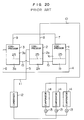
- This type of capacity controllable compressor apparatus has, as shown in Figure 20, a plurality of parallel-connected compressors with their oil sumps connected with each other by means of oil equalizing pipes, so that the overall capacity thereof is controlled by making inoperative some of the compressors or by varying the capacities of the compressors.
- the liquid refrigerant thus dissolved is compressed and occurs foaming to increase the amount of the oil drawn into the compression space, so that the efficiency of the compressor is decreased.
- the internal pressure in the chamber of the inoperative compressor becomes slightly lower than the internal pressure in the chamber of the compressor in operation, so that there is a problem in this case as well that the lubricating oil is distributed nonuniformly among the compressors.
- USA-A-3581519 illustrates a compressor apparatus as set out in the first parts of claims 1 and 5.
- US-A-4411141 illustrates a compressor apparatus having two compressors in which oil can pass from a compressor having higher oil chamber pressure to the other.
- Polytechnisch Tijdschrift, Vol. 21a, No. 5, 2 March 1966, pages 206A-210A shows a multi-compressor apparatus in which shut-off valves are provided in the connecting oil pipes between the compressors, to shut off flow when one compressor is out of operation.
- An object of the present invention is to control the distribution of lubricating oil when the compressors are selectively operated. Another object is to reduce or prevent dilution of the lubricating oil by dissolved lubricant.
- the present invention can provide a compressor apparatus which is free from the lowering of the efficiency of the compressor due to an increase in the amount of the oil drawn into the compression space attributable to compression and foaming of liquid refrigerant when the inoperative compressor is started again.
- a capacity controllable compressor apparatus in one aspect is set out in claim 1.
- a capacity controllable compressor apparatus in a second aspect is set out in claim 5.
- the lubricating oil separated from the high-pressure gas refrigerant by the oil separator is returned to the compressor operated at an increased internal pressure and then supplied from this compressor to the other compressors. It is therefore possible to prevent the nonuniform distribution of the lubricating oil.
- the lubricating oil is returned to the compressor operated at an increased internal pressure among the compressors in operation with the inoperative compressor isolated within the circuit, thereby preventing the high-pressure gas refrigerant and the lubricating oil from flowing into the inoperative compressor. It is therefore possible to prevent the nonuniform distribution of the lubricating oil and to prevent the compression of the liquid refrigerant and the occurrence of the foaming when the inoperative compressor is started again, thereby avoiding the lowering of the efficiency of the compressor apparatus.
- FIG. 1 shows a first compressor apparatus given by way of explanation.
- the compressor apparatus has three high-pressure chamber compressors 1, 2 and 3 which are connected in parallel to a common suction pipe 10 and a common discharge pipe 11.
- the compressors 1, 2 and 3 are of the fixed capacity type.
- the compressor 1 is operated at a higher frequency than the other compressors 2 and 3. Further, the compressor 2 is operated at a higher frequency than the compressor 3.
- An oil sump 1b of the compressor 1 is communicated with an oil sump 2b of the compressor 2 by means of an oil equalizing pipe 15a, and the oil sump 2b of the compressor 2 is communicated with an oil sump 3b of the compressor 3 by means of an oil equalizing pipe 15b.
- the oil equalizing pipes 15a and 15b are provided with check valves 22a and 22b, respectively, so that the check valves 22a and 22b permit lubricating oil to flow from the compressor 1 to the compressor 2 and from the compressor 2 to the compressor 3, respectively.
- a suction pipe 7 of the compressor 1 is communicated with a suction pipe 8 of the compressor 2 by means of a communication pipe 17a, and the suction pipe 8 of the compressor 2 is communicated with a suction pipe 9 of the compressor 3 by means of a communication pipe 17b.
- Discharge pipes 4 and 5 are provided with check valves 20a and 20b, respectively, so as to prevent the backward flowing of compressed gas.
- the common discharge pipe 11 is provided with an oil separator 16 for separating the lubricating oil from the high pressure gas, a high-pressure gas refrigerant in this apparatus, discharged from each of the compressors.
- An oil return pipe 18 is connected to the oil separator 16 for returning the lubricating oil thus separated to the compressors.
- the oil return pipe 18 is connected to the suction pipe 7 of the compressor 1 at a point upstream of a point where the communication pipe 17a is connected to the suction pipe 7.
- a check valve 21a is disposed in the suction pipe 7 at a point downstream of the point of connection of the communication pipe 17a so as to prevent the refrigerant from flowing out of the compressor 1.
- a check valve 21b is disposed in the suction pipe 8 of the compressor 2.
- a condenser 12 is connected to the oil separator 16.
- a plurality of parallel-connected evaporators 14 are connected to the condenser 12 through decompression devices 13. Each of the evaporators 14 is connected to the common suction pipe 10, thus completing a refrigerating cycle.
- the compressor 1 is operated at a higher frequency, that is, with a larger capacity, than the other compressor 2, 3 so that the velocity of the refrigerant flowing through the discharge pipe 4 of the compressor 1 becomes higher than that of the refrigerant flowing through the discharge pipes 5, 6 of the other compressors 2, 3.
- the pressure loss in the discharge pipe 4 becomes greater than that in the discharge pipes 5, 6. Since the pressure is equalized in the common discharge pipe 11 to which the respective discharge pipes 4, 5 and 6 are connected, the internal pressure of the chamber of the compressor 1 is increased by an amount corresponding to a difference in the pressure loss.
- the high-pressure gas refrigerant containing the lubricating oil is discharged from the respective compressors 1, 2 and 3 to be separated from the lubricating oil by means of the oil separator 16 and then introduced to the condenser 12 through the common discharge pipe 11.
- the lubricating oil thus separated is returned through the oil return pipe 18 and a decompression device 19 to the suction pipe 7 of the compressor 1.
- the lubricating oil is then returned to the respective compressors 1, 2 and 3 through the suction pipe 7 and the communication pipes 17a and 17b.
- the lubricating oil gathered in the oil sump 1b of the compressor 1 is supplied to the compressors 2 and 3 through the oil equalizing pipes 15a and 15b due to a difference in the internal pressure between the compressors 1 and 2.
- the oil equalizing pipes 15a and 15b extend to project into the oil sumps of the compressors located on the upstream side as shown in Figure 1, when an oil level 25 in the compressor on the upstream side is lowered below an opening of the oil equalizing pipe 15a or 15b, it is prevented that the returned lubricating oil is supplied to the compressor on the downstream side by flowing down along the chamber wall of the compressor, thus making it possible to keep the oil level 25 in the compressor on the upstream side at a regular position. It is therefore possible to prevent the nonuniform distribution of the lubricating oil.
- the compressor apparatus When the compressor apparatus is operated in a capacity controlling mode in which the compressor 1 is made inoperative, the high-pressure gas refrigerant discharged through the discharge pipes 5 and 6 of the compressors 2 and 3 is prevented from flowing into the compressor 1 by means of the check valve 20a disposed in the discharge pipe 4 of the compressor 1.
- the lubricating oil separated from the high-pressure gas refrigerant by means of the oil separator 16 is returned to the suction pipe 7 of the compressor 1 through the oil return pipe 18 and the decompression device 19. Since the inside of the compressor 1 is kept at a high internal pressure by means of the check valve 21a, the lubricating oil thus returned is not allowed to flow into the compressor 1 but made to return to the suction pipe 8 of the compressor 2 through the communication pipe 17a.
- the lubricating oil is then returned to the compressors 2 and 3 through the suction pipe 8 and the communication pipe 17b. Further, the lubricating oil gathered in the oil sump 2b of the compressor 2 is supplied through the oil equalizing pipe 15b to the compressor 3 due to a difference in the internal pressure between the compressors 2 and 3. The lubricating oil in the compressor 2 is prevented from being supplied to the compressor 1 by means of the check valve 22a of the oil equalizing pipe 15a.
- the oil equalizing pipe 15b extends to project into the oil sump of the compressor 2 located on the upstream side as shown in Figure 1, when the oil level 25 in the compressor 2 on the upstream side is lowered below the opening of the oil equalizing pipe 15b, the returned lubricating oil is prevented from being supplied to the compressor 3 on the downstream side by flowing down along the chamber wall of the compressor 2, thus making it possible to keep the oil level 25 in the compressor 2 on the upstream side at a regular position. It is therefore possible to prevent the lubricating oil from being nonuniformly distributed between the compressors 2 and 3 and to keep the quantity of the lubricating oil in the oil sump of the compressor 1 at a regular quantity.
- the compressor apparatus when the compressor apparatus is operated in a capacity controlling mode in which the compressor 3 alone is operated while the compressors 1 and 2 are made inoperative, the high-pressure gas refrigerant discharged from the compressor 3 is prevented from flowing into the compressors 1 and 2 by means of the check valves 20a and 20b in the same manner as mentioned above. Further, the lubricating oil separated by means of the oil separator 16 is returned through the oil return pipe 18 while being prevented from flowing into the compressors 1 and 2 by means of the check valves 21a and 21b. In consequence, it is possible, in this case as well, to prevent dilution of the lubricating oil, compression and foaming of the liquid refrigerant.
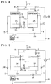
- Figure 2 shows a second compressor apparatus given by way of explanation.
- this apparatus two high-pressure chamber compressors 1 and 2 are connected in parallel, and the compressor 1 is operated at a higher frequency than the compressor 2.
- An oil equalizing pipe 15 is provided with a stop valve 23 which serves to close the oil equalizing pipe 15, in place of the check valves 22a and 22b.
- Other arrangements are identical with those of the apparatus of Fig. 1 so that explanation thereof will be omitted.
- the stop valve 23 disposed in the oil equalizing pipe 15 is opened.
- the compressor 1 is operated at a higher frequency, that is, with a larger capacity, than the compressor 2 so that the velocity of the refrigerant flowing through the discharge pipe 4 of the compressor 1 becomes higher than that of the refrigerant flowing through the discharge pipe 5 of the compressor 2. In consequence, the pressure loss in the discharge pipe 4 becomes greater than that in the discharge pipe 5. Since the pressure is equalized in the common discharge pipe 11 to which the respective discharge pipes 4 and 5 are connected, the internal pressure of the chamber of the compressor 1 is increased by an amount corresponding to a difference in the pressure loss.
- the high-pressure gas refrigerant containing the lubricating oil is discharged from the respective compressors 1 and 2 to be separated from the lubricating oil by means of the oil separator 16 and is then fed to the condenser (not shown in Fig. 2).
- the lubricating oil thus separated is returned through the oil return pipe 18 and the decompression device 19 to the suction pipe 7 of the compressor 1.
- the lubricating oil is then returned to the respective compressors 1 and 2 through the suction pipe 7 and the communication pipe 17. Further, the lubricating oil gathered in the oil sump lb of the compressor 1 is supplied to the compressor 2 through the oil equalizing pipe 15 due to a difference in the internal pressure between the compressors 1 and 2.
- the oil equalizing pipe 15 extends to project into the oil sump lb of the compressor 1 located on the upstream side similarly to the apparatus of Fig. 1, when the oil level 25 in the compressor 1 on the upstream side is lowered below the opening of the oil equalizing pipe 15, the returned lubricating oil is prevented from being supplied to the compressor 2 on the downstream side by flowing down along the chamber wall of the compressor, thus making it possible to keep the oil level 25 in the compressor 1 on the upstream side at a regular position. It is therefore possible to prevent the nonuniform distribution of the lubricating oil.
- the compressor apparatus When the compressor apparatus is operated in a capacity controlling mode in which the compressor 1 is made inoperative, the high-pressure gas refrigerant discharged through the discharge pipe 5 of the compressor 2 is prevented from flowing into the compressor 1 by means of the check valve 20 disposed in the discharge pipe 4 of the compressor 1.
- the lubricating oil separated from the high-pressure gas refrigerant by means of the oil separator 16 is returned to the suction pipe 7 of the compressor 1 through the oil return pipe 18 and the decompression device 19. Since the inside of the compressor 1 is kept at a high internal pressure by means of the check valve 21, the lubricating oil thus returned is not allowed to flow into the compressor 1 but made to return to the suction pipe 8 of the compressor 2 through the communication pipe 17.
- the lubricating oil is then returned to the compressor 2 through the suction pipe 8 and the communication pipe 17.
- the lubricating oil in the compressor 2 is prevented from being supplied to the compressor 1 by closing the stop valve 23 of the oil equalizing pipe 15. It is therefore possible to keep the lubricating oil in the compressor 2 in the normal state. Further, since the high-pressure gas refrigerant discharged from the compressor 2 is prevented from flowing into the compressor 1, there is no possibility that the refrigerant dissolves in the lubricating oil in the compressor 1 to dilute the lubricating oil. In addition, even when the compressor 1 is started again, there is no compression of the liquid refrigerant and no occurrence of foaming, thereby preventing the lowering of the efficiency of the compressor apparatus.
- FIG 3 shows a third compressor apparatus given by way of explanation.
- a check valve 24 is disposed, in addition, in the discharge pipe 5 of the compressor 2 of the apparatus of Figure 2 so as to prevent the high-pressure gas refrigerant from flowing into the compressor 2.
- Other arrangements are identical with those of the apparatus of Figure 2 so that explanation thereof will be omitted.
- the compressor apparatus When the compressor apparatus is operated in a capacity controlling mode in which the compressor 2 is made inoperative, the high-pressure gas refrigerant discharged through the discharge pipe 4 of the compressor 1 is prevented from flowing into the compressor 1 by means of the check valve 24 disposed in the discharge pipe 5 of the compressor 2.
- the lubricating oil separated from the high-pressure gas refrigerant by means of the oil separator 16 is returned to the suction pipe 7 of the compressor 1 through the oil return pipe 18 and the decompression device 19 by which the pressure of the lubricating oil is reduced to a suction pressure level.
- the returned lubricating oil kept at the suction pressure is scarcely allowed to flow into the compressor 2 through the communication pipe 17 so as to be returned to the compressor 1.
- the lubricating oil in the compressor 1 is prevented from being supplied to the compressor 2 by closing the stop valve 23 of the oil equalizing pipe 15. It is therefore possible to keep the lubricating oil in the compressor 1 in the normal state. Further since the high-pressure gas refrigerant discharged from the compressor 1 is prevented from flowing into the compressor 2, there is no possibility that the refrigerant dissolves in the lubricating oil in the compressor 2 to dilute the lubricating oil.
- FIGs 4 and 5 show respectively fourth and fifth apparatuses given by way of explanation.
- the fourth and fifth apparatuses are modifications of the second and third apparatuses of Figures 2 and 3, respectively, in which a throttle 26 serving to increase the flow resistance of the pipe is disposed in the discharge pipe 4.
- the length and/or the diameter of the pipe may be adjusted to increase the flow resistance.
- Figures 6 and 7 show respectively sixth and seventh apparatuses, given by way of explanation, and different from the apparatuses of Figures 2 and 3 in that compressors 27 and 28 are used in place of the compressors 1 and 2.
- the compressor 27 has a larger capacity than the compressor 28.
- FIGS. 8 to 13 show respectively first to sixth embodiments of the compressor apparatus according to the present invention. In these embodiments, only the compressors 2 and 28 are enabled to be made inoperative.
- the first embodiment ( Figure 8) is a modification of the apparatus of Figure 3, in which the communication pipe 17, the check valve 21 and the check valve 20 of the discharge pipe 4 of the compressor 1 are dispensed with.
- the compressors 1 and 2 are fixed capacity type high-pressure chamber compressors, and the compressor 1 is operated at a high frequency.
- the stop valve 23 disposed in the oil equalizing pipe 15 is opened.
- the high-pressure gas refrigerant containing the lubricating oil is discharged from the respective compressors 1 and 2 to be separated from the lubricating oil by means of the oil separator 16 and is then fed to the condenser which is not shown.
- the lubricating oil thus separated is returned through the oil return pipe 18 and the decompression device 19 to the suction pipe 7 of the compressor 1.
- the lubricating oil is then returned to the compressor 1 through the suction pipe 7.
- the lubricating oil gathered in the oil sump lb of the compressor 1 is supplied through the oil equalizing pipe 15 to the compressor 2 due to a difference in the internal pressure between the compressors 1 and 2.
- the oil equalizing pipe 15 extends to project into the oil sump 1b of the compressor 1 located on the upstream side similarly to the apparatus of Figure 1, when the oil level 25 in the compressor 1 on the upstream side is lowered below the opening of the oil equalizing pipe 15, the returned lubricating oil is prevented from being supplied to the compressor 2 on the downstream side by flowing down along the chamber wall of the compressor, thus making it possible to keep the oil level 25 in the compressor 1 on the upstream side at a regular position. It is therefore possible to prevent the nonuniform distribution of the lubricating oil between the compressors 1 and 2.
- the compressor apparatus When the compressor apparatus is operated in a capacity controlling mode in which the compressor 2 is made inoperative, the high-pressure gas refrigerant discharged through the discharge pipe 4 of the compressor 1 is prevented from flowing into the compressor 2 by means of the check valve 24 disposed in the discharge pipe 5 of the compressor 2.
- the lubricating oil separated from the high-pressure gas refrigerant by means of the oil separator 16 is returned to the suction pipe 7 of the compressor 1 through the oil return pipe 18 and the decompression device 19 and is then returned to the compressor 1.
- the lubricating oil in the compressor 1 is prevented from being supplied to the compressor 2 by closing the stop valve 23 of the oil equalizing pipe 15. It is therefore possible to keep the lubricating oil in the compressor 2 in the normal state.
- the second embodiment is a modification of the first embodiment ( Figure 8), in which the oil return pipe 18 is connected with a space lc in the compressor 1, the pressure in the space lc corresponding to an intermediate pressure obtained in the course of the compression stroke.
- the efficiency of the compressor can be increased owing to the cooling effect of the lubricating oil.
- the third and fourth embodiments are modifications of the first and second embodiments ( Figures 8 and 9), respectively, in which the throttle 26 is disposed in the discharge pipe 4 of the compressor 1 instead of operating the compressor 1 at a high frequency.
- the length and/or the diameter of the pipe may be adjusted to increase the flow resistance.
- the fifth and sixth embodiments are modifications of the first and second embodiments ( Figures 8 and 9), respectively, in which the compressors 27 and 28 are used in place of the compressors 1 and 2.
- the compressor 27 has a larger capacity and a higher internal pressure than the compressor 28.
- Figures 14 to 19 show respectively seventh to twelfth embodiments of the compressor apparatus according to the present invention.
- the parallel-connected high-pressure chamber compressors 1 and 2 are both enabled to be made inoperative for the purpose of controlling the capacity.
- the fourteenth embodiment is a modification of the eighth embodiment, in which the check valve 20 is disposed in the discharge pipe 4 of the compressor 1 so as to prevent the high-pressure gas refrigerant from flowing into the compressor 1, an oil return pipe 32 is connected between the oil separator 16 and the suction pipe 8 of the compressor 2, the oil return pipe 32 is provided with a stop valve 30 serving to close the oil return pipe 32 and a decompression device 31, and the oil return pipe 18 is provided with a stop valve 29 serving to close the oil return pipe 18. Further, the oil equalizing pipe 15 through which the oil sumps 1b and 2b of the compressors 1 and 2 are connected with each other extends to project into both the oil sumps 1b and 2b.
- the compressor 1 is operated at a higher frequency, that is, with a larger capacity, than the compressor 2.
- the stop valve 23 disposed in the oil equalizing pipe 15 is opened, the stop valve 30 of the oil return pipe 32 is closed, and the stop valve 29 of the oil return pipe 18 is opened.
- the high-pressure gas refrigerant containing the lubricating oil is discharged from the respective compressors 1 and 2 to be separated from the lubricating oil by means of the oil separator 16 and is then fed to the condenser which is not shown.
- the lubricating oil thus separated is returned through the oil return pipe 18 and the decompression device 19 to the suction pipe 7 of the compressor 1.
- the lubricating oil is then returned to the compressor 1 through the suction pipe 7.
- the lubricating oil gathered in the oil sump 1b of the compressor 1 is supplied through the oil equalizing pipe 15 to the compressor 2 due to a difference in the internal pressure between the compressors 1 and 2. Since the oil equalizing pipe 15 extends to project into the oil sump 1b of the compressor 1 located on the upstream side similarly to the first embodiment, when the oil level 25 in the compressor 1 on the upstream side is lowered below the opening of the oil equalizing pipe 15, the returned lubricating oil is prevented from being supplied to the compressor 2 on the downstream side by flowing down along the chamber wall of the compressor 1, thus making it possible to keep the oil level 25 in the compressor 1 on the upstream side at a regular position. It is therefore possible to prevent the nonuniform distribution of the lubricating oil between the compressors 1 and 2.
- the stop valves 23 and 30 are closed.
- the high-pressure gas refrigerant discharged through the discharge pipe 4 of the compressor 1 is prevented from flowing into the compressor 2 by means of the check valve 24 disposed in the discharge pipe 5 of the compressor 2.
- the lubricating oil separated from the high-pressure gas refrigerant by means of the oil separator 16 is returned to the suction pipe 7 of the compressor 1 through the oil return pipe 18 and the decompression device 19 and is then returned to the compressor 1.
- the lubricating oil in the compressor 1 is prevented from being supplied to the compressor 2 by closing the stop valve 23 of the oil equalizing pipe 15. It is therefore possible to keep the lubricating oil in the compressor 2 in the normal state.
- the stop valves 23 and 29 are closed.
- the high-pressure gas refrigerant discharged through the discharge pipe 5 of the compressor 2 is prevented from flowing into the compressor 1 by means of the check valve 20 disposed in the discharge pipe 4 of the compressor 1.
- the lubricating oil separated from the high-pressure gas refrigerant by means of the oil separator 16 is returned to the suction pipe 8 of the compressor 2 through the oil return pipe 32 and the decompression device 31 and is then returned to the compressor 2.
- the lubricating oil in the compressor 2 is prevented from being supplied to the compressor 1 by closing the stop valve 23 of the oil equalizing pipe 15. It is therefore possible to keep the lubricating oil in the compressor 1 in the normal state.
- the high-pressure gas refrigerant discharged from the compressor 2 is prevented from flowing into the compressor 1 by means of the check valve 20, there is no possibility that the refrigerant dissolves in the lubricating oil in the compressor 1 to dilute the lubricating oil.
- the compressor 1 is started again, there is no compression of the liquid refrigerant and no occurrence of the foaming, thereby preventing the lowering of the efficiency of the compressor apparatus.
- the compressor to be made inoperative for controlling the capacity is not specified, the lifetime of the compressor apparatus can be extended.
- the eight embodiment ( Figure 15) is a modification of the seventh embodiment ( Figure 14), in which the oil return pipes 18 and 32 are connected with spaces 1c and 2c in the compressors 1 and 2, respectively, the pressure in each space 1c, 2c corresponding to an intermediate pressure obtained in the course of the compression stroke.
- the efficiency of the compressor can be increased owing to the cooling effect of the lubricating oil.
- the ninth and tenth embodiments are modifications of the seventh and eighth embodiments ( Figures 14 and 15), respectively, in which the compressors 27 and 28 are used in place of the compressors 1 and 2, and the compressor 27 has a larger capacity and a higher internal pressure than the compressor 28.
- the eleventh and twelfth embodiments are modifications of the seventh and eighth embodiments ( Figures 14 and 15), respectively, in which variable capacity type high-pressure chamber compressors 33 and 34 are used in place of the fixed capacity type high-pressure chamber compressors 1 and 2.
Landscapes
- Engineering & Computer Science (AREA)
- General Engineering & Computer Science (AREA)
- Mechanical Engineering (AREA)
- Physics & Mathematics (AREA)
- Thermal Sciences (AREA)
- Compressors, Vaccum Pumps And Other Relevant Systems (AREA)
- Compressor (AREA)
- Applications Or Details Of Rotary Compressors (AREA)
Claims (15)
- Verdichteranlage mit steuerbarer Leistung mit einer Vielzahl an Verdichtern (1, 2; 27, 28), die parallel mit einem gemeinsamen Kühlmittelansaugrohr (10) und über Auslaßrohre (4, 5) mit einem gemeinsamen Kühlmittelauslaßrohr (11) verbunden sind, und (ein) Ölausgleichsrohr(e) (15) aufweisen, durch das/die Ölwannen (1b, 2b; 27b, 28b) der genannten Vielzahl an Verdichtern miteinander verbunden sind, wobei genannte Verdichteranlage weiters einen mit dem genannten gemeinsamen Auslaßrohr (11) verbundenen Ölabscheider (16), Mittel (18) zum Rückführen von durch den genannten Ölabscheider (16) abgeschiedenem Schmieröl zur Ansaugseite der genannten Verdichter (1, 2; 27, 28) und ein erstes Steuerungsmittel (23) in genanntem/genannten Ölausgleichsrohr(en) (15) umfaßt und betreibbar ist, das Schmieröl daran zu hindern, über genannte(s) Ölausgleichsrohr(e) aus einem in Betrieb befindlichen der genannten Verdichter zu einem anderen davon zu fließen, der außer Betrieb gesetzt wurde, um die Steuerung der Leistung der Verdichteranlage durchzuführen,
dadurch gekennzeichnet, daß genannte Verdichter Hochdruckkammerverdichter sind, in denen Ölwannen einem Auslaßgasdruck ausgesetzt sind, daß einer der genannten Vielzahl an Verdichtern (1, 2; 27, 28) so betrieben wird, daß seine Druckkammer auf einem höheren Innendruck gehalten wird als jene des anderen Verdichters oder der anderen Verdichter, daß genanntes Mittel (18) zum Rückführen von Schmieröl aus genanntem Ölabscheider so angeordnet ist, um genanntes Öl nur zu jenem der genannten Verdichter zurückzuleiten, der mit höherem Innendruck der Druckkammer betrieben wird, und daß Ventilmittel (24) in einem Auslaßrohr (4, 5) von zumindest einem der genannten Verdichter angeordnet sind, um ein Fließen des Kühlmittels aus einem in Betrieb befindlichen in einen nicht in Betrieb befindlichen der genannten Verdichter zu verhindern. - Verdichteranlage mit steuerbarer Leistung nach Anspruch 1, worin genanntes Ventilmittel Absperrventile (24) enthält, die angeordnet sind, um ein Fließen des Kühlmittels aus einem in Betrieb befindlichen in einen nicht in Betrieb befindlichen genannten Verdichter zu verhindern.
- Verdichteranlage mit steuerbarer Leistung nach Anspruch 1 oder Anspruch 2, worin genanntes Schmierölrückführmittel ein Ölrückführrohr (18) enthält, das zwischen genanntem Ölabscheider (16) und einem Kühlmittelansaugrohr (7) verbunden ist, das mit jenem genannten Verdichter verbunden ist, der mit auf einem hohen Innendruck gehaltener Druckkammer betrieben wird.
- Verdichteranlage mit steuerbarer Leistung nach einem der Ansprüche 1 bis 3, worin ein Auslaßrohr (4) des genannten einen Verdichters, der mit bei einem hohen Innendruck gehaltener Kammer betrieben wird, einen größeren Flußwiderstand (26) aufweist als jenes des zumindest einen anderen Verdichters.
- Verdichteranlage mit steuerbarer Leistung mit einer Vielzahl an Verdichtern (1, 2; 33, 34), die parallel mit einem gemeinsamen Kühlmittelansaugrohr (10) und über Auslaßrohre (4, 5) mit einem gemeinsamen Kühlmittelauslaßrohr (11) verbunden sind und (ein) Ölausgleichsrohr(e) (11) aufweisen, durch das/die Ölwannen (1b, 2b; 33b, 34b) der genanten Vielzahl an Verdichtern miteinander verbunden sind, wobei genannte Verdichteranlage weiters einen mit dem genannten gemeinsamen Auslaßrohr (11) verbundenen Ölabscheider (16), Mittel (18, 29, 30, 32) zum Rückführen des durch genannten Ölabscheider (16) abgeschiedenen Schmieröls zu einer Ansaugseite der genannten Verdichter (1, 2; 33, 34) und ein erstes Steuerungsmittel (23) in genanntem/genannten Ausgleichsrohr(en) (15) umfaßt und betreibbar ist, zu verhindern, daß das Schmieröl über genanntes/genannte Ölausgleichsrohr(e) aus einem in Betrieb befindlichen der genannten Verdichter zu einem anderen davon fließt, der außer Betrieb gesetzt wurde, um die Steuerung der Leistung der Verdichteranlage durchzuführen,
dadurch gekennzeichnet, daß genannte Verdichter Hochdruckkammerverdichter sind, in denen die Ölwannen einem Auslaßgasdruck ausgesetzt sind, daß einer der genannten Vielzahl an Verdichtern (1, 2; 33, 34) so betrieben wird, daß seine Druckkammer bei einem höheren Innendruck gehalten wird als jene des anderen Verdichters oder der anderen Verdichter, daß genanntes Mittel (18, 29, 30, 32) zum Rückführen des Schmieröls aus genanntem Ölabscheider ein Absperrventilmittel (29, 30) zum Steuern der Ölrückführung zu jedem Verdichter aufweist, sodaß Öl zu jenem genannten Verdichter zurückgeleitet werden kann, der mit seiner Druckkammer auf hohem Innendruck betrieben wird, und daß Ventilmittel (20, 24) in einem Auslaßrohr (4, 5) von zumindest einem der genannten Verdichter angeordnet sind, um ein Fließen des Kühlmittels aus einem in Betrieb befindlichen in einen nicht in Betrieb befindlichen der genannten Verdichter zu verhindern. - Verdichteranlage mit steuerbarer Leistung nach Anspruch 5, worin genanntes Schmierölrückführmittel Ölrückführungsrohre (18, 32) aufweist, von denen jedes zwischen genanntem Ölabscheider (16) und Zwischenräumen (1c, 2c; 27c, 28c; 33c, 34c) in genannter Vielzahl an Verdichtern (1, 2; 27, 28; 33, 34) verbunden ist, wobei der Druck in jedem Zwischenraum einem Zwischendruck entspricht, der im Verlauf eines Verdichtungshubs entsteht, und wobei Absperrventile (29, 30) dazu dienen, die genannten Ölrückführungsrohre zu schließen.
- Verdichteranlage mit steuerbarer Leistung nach Anspruch 5 oder Anspruch 6, worin genanntes Schmierölrückführungsmittel Ölrückführungsrohre (18, 32), die jeweils zwischen dem genannten Ölabscheider (16) und Kühlmittelansaugrohren (7, 8), die mit einer Vielzahl an Verdichtern (1, 2; 27, 28; 33, 34) verbunden sind, verbunden sind und Absperrventile (29, 30) aufweist, die zum Schließen der genannten Ölrückführungsrohre (18, 32) dienen.
- Verdichteranlage mit steuerbarer Leistung nach einem der Ansprüche 1 bis 7, worin genanntes erstes Steuerungsmittel ein Absperrventil (23) zum Schließen des genannten Ölausgleichsrohres (15) enthält, um ein Fließen des Schmieröls aus einem in Betrieb befindlichen in einen nicht in Betrieb befindlichen der genannten Verdichter zu verhindern.
- Verdichteranlage mit steuerbarer Leistung nach einem der Ansprüche 1 bis 8, worin genanntes Schmierölrückführungsmittel ein Ölrückführungsrohr (18) enthält, das zwischen genanntem Ölabscheider (16) und einem Zwischenraum (1c, 27c) in jenem genannten Verdichter verbunden ist, der mit seiner auf hohem Innendruck gehaltenen Druckkammer betrieben wird, wobei der Druck in genanntem Zwischenraum einem Zwischendruck entspricht, der im Verlauf eines Verdichtungshubs entsteht.
- Verdichteranlage mit steuerbarer Leistung nach einem der Ansprüche 1 bis 9, worin genannte Vielzahl an Hochdruckkammerverdichtern (1, 2, 3) Verdichter mit fixer Leistung sind.
- Verdichteranlage mit steuerbarer Leistung nach einem der Ansprüche 1 bis 10, worin von genannter Vielzahl an Hochdruckkammerverdichtern (33, 34) zumindest jener Verdichter, der mit bei einem höheren Innendruck gehaltener Kammer betrieben wird, ein Verdichter mit variabler Leistung ist.
- Verdichteranlage mit steuerbarer Leistung nach Anspruch 10, worin genannter Verdichter (27), der mit bei einem höheren Innendruck gehaltener Kammer betrieben wird, eine größere Leistung als der/die andere(n) Verdichter aufweist.
- Verdichteranlage mit steuerbarer Leistung nach Anspruch 11, worin genannter Verdichter (33), der mit bei einem höheren Innendruck gehaltener Kammer betrieben wird, eine größere Leistung als der/die andere(n) Verdichter aufweist.
- Verdichteranlage mit steuerbarer Leistung nach einem der Ansprüche 1 bis 13, worin genanntes Schmierölrückführungsmittel Dekompressionsgeräte (19; 19, 31) aufweist.
- Verdichteranlage mit steuerbarer Leistung nach einem der Ansprüche 1 bis 14, worin sich genannte(s) Ölausgleichsrohr(e) (15a, 15b; 15) so erstreckt/erstrecken, daß es/sie in die Ölwanne des genannten Verdichters ragt/ragen, der in bezug auf den Schmierölfluß an der stromaufwärtigen Seite angeordnet ist.
Applications Claiming Priority (2)
| Application Number | Priority Date | Filing Date | Title |
|---|---|---|---|
| JP1149668A JP2865707B2 (ja) | 1989-06-14 | 1989-06-14 | 冷凍装置 |
| JP149668/89 | 1989-06-14 |
Publications (3)
| Publication Number | Publication Date |
|---|---|
| EP0403239A2 EP0403239A2 (de) | 1990-12-19 |
| EP0403239A3 EP0403239A3 (de) | 1991-03-20 |
| EP0403239B1 true EP0403239B1 (de) | 1994-08-24 |
Family
ID=15480229
Family Applications (1)
| Application Number | Title | Priority Date | Filing Date |
|---|---|---|---|
| EP90306416A Expired - Lifetime EP0403239B1 (de) | 1989-06-14 | 1990-06-13 | Verdichteranlage mit steuerbarer Leistung |
Country Status (5)
| Country | Link |
|---|---|
| US (1) | US5094598A (de) |
| EP (1) | EP0403239B1 (de) |
| JP (1) | JP2865707B2 (de) |
| KR (1) | KR940003310B1 (de) |
| ES (1) | ES2058800T3 (de) |
Cited By (1)
| Publication number | Priority date | Publication date | Assignee | Title |
|---|---|---|---|---|
| CN105157277A (zh) * | 2014-06-03 | 2015-12-16 | 广东美的暖通设备有限公司 | 多联机空调系统 |
Families Citing this family (70)
| Publication number | Priority date | Publication date | Assignee | Title |
|---|---|---|---|---|
| US5369958A (en) * | 1992-10-15 | 1994-12-06 | Mitsubishi Denki Kabushiki Kaisha | Air conditioner |
| WO1996000872A1 (en) * | 1994-06-29 | 1996-01-11 | Daikin Industries, Ltd. | Oil balancing operation control device for an air conditioner |
| US6206652B1 (en) | 1998-08-25 | 2001-03-27 | Copeland Corporation | Compressor capacity modulation |
| DE19823525A1 (de) * | 1998-05-26 | 1999-12-02 | Linde Ag | Verbund(kälte)anlage und Verfahren zum Betreiben einer Verbund(kälte)anlage |
| DE19823524A1 (de) * | 1998-05-26 | 1999-12-02 | Linde Ag | Verbund(kälte)anlage und Verfahren zum Betreiben einer Verbund(kälte)anlage |
| JP4610742B2 (ja) | 1999-01-12 | 2011-01-12 | エックスディーエックス・テクノロジー・エルエルシー | ベーパ圧縮装置及び方法 |
| AU759727B2 (en) | 1999-01-12 | 2003-04-17 | Xdx Inc. | Vapor compression system and method |
| US6314747B1 (en) | 1999-01-12 | 2001-11-13 | Xdx, Llc | Vapor compression system and method |
| US6185958B1 (en) | 1999-11-02 | 2001-02-13 | Xdx, Llc | Vapor compression system and method |
| DE60031565T2 (de) * | 1999-11-02 | 2007-08-30 | XDX Technology LLC, Arlington Heights | Dampfkompressionssystem und verfahren zur steuerung der umgebungsverhältnisse |
| JP4499863B2 (ja) * | 2000-01-21 | 2010-07-07 | 東芝キヤリア株式会社 | マルチ形空気調和機 |
| KR100405238B1 (ko) | 2000-01-21 | 2003-11-12 | 도시바 캐리어 가부시키 가이샤 | 오일량 검출기, 냉동장치 및 공기조화기 |
| TWI237682B (en) * | 2000-07-07 | 2005-08-11 | Sanyo Electric Co | Freezing apparatus |
| US20050092002A1 (en) * | 2000-09-14 | 2005-05-05 | Wightman David A. | Expansion valves, expansion device assemblies, vapor compression systems, vehicles, and methods for using vapor compression systems |
| US6857281B2 (en) | 2000-09-14 | 2005-02-22 | Xdx, Llc | Expansion device for vapor compression system |
| US6915648B2 (en) * | 2000-09-14 | 2005-07-12 | Xdx Inc. | Vapor compression systems, expansion devices, flow-regulating members, and vehicles, and methods for using vapor compression systems |
| US6401470B1 (en) | 2000-09-14 | 2002-06-11 | Xdx, Llc | Expansion device for vapor compression system |
| US6393851B1 (en) | 2000-09-14 | 2002-05-28 | Xdx, Llc | Vapor compression system |
| US6401485B1 (en) * | 2000-10-06 | 2002-06-11 | American Standard Inc. | Discharge refrigerant heater for inactive compressor line |
| JP3750520B2 (ja) * | 2000-12-08 | 2006-03-01 | ダイキン工業株式会社 | 冷凍装置 |
| DE20115270U1 (de) * | 2001-09-15 | 2001-11-22 | Teko Ges Fuer Kaeltetechnik Mb | Kühlanlage und zugehörige Schaltungsanordnung |
| KR20030084426A (ko) * | 2002-04-26 | 2003-11-01 | 캐리어엘지 유한회사 | 압축기 윤활 장치의 윤활유 차단 장치 |
| JP4300804B2 (ja) * | 2002-06-11 | 2009-07-22 | ダイキン工業株式会社 | 圧縮機構の均油回路、冷凍装置の熱源ユニット及びそれを備えた冷凍装置 |
| KR100792055B1 (ko) * | 2003-05-15 | 2008-01-04 | 엘지전자 주식회사 | 실외기용 가변형 압축기의 냉매 토출 유로 |
| KR100504900B1 (ko) * | 2003-10-10 | 2005-07-29 | 엘지전자 주식회사 | 4대의 압축기를 구비한 공기조화기 및 그의 균유운전 제어방법 |
| US6966192B2 (en) * | 2003-11-13 | 2005-11-22 | Carrier Corporation | Tandem compressors with discharge valve on connecting lines |
| US20080098760A1 (en) * | 2006-10-30 | 2008-05-01 | Electro Industries, Inc. | Heat pump system and controls |
| US7849700B2 (en) * | 2004-05-12 | 2010-12-14 | Electro Industries, Inc. | Heat pump with forced air heating regulated by withdrawal of heat to a radiant heating system |
| US7802441B2 (en) * | 2004-05-12 | 2010-09-28 | Electro Industries, Inc. | Heat pump with accumulator at boost compressor output |
| KR101073501B1 (ko) * | 2004-05-18 | 2011-10-17 | 삼성전자주식회사 | 다단운전 공기조화기 |
| US7231783B2 (en) * | 2004-08-27 | 2007-06-19 | Zero Zone, Inc. | Oil control system for a refrigeration system |
| US20060073026A1 (en) * | 2004-10-06 | 2006-04-06 | Shaw David N | Oil balance system and method for compressors connected in series |
| KR100775821B1 (ko) * | 2004-12-15 | 2007-11-13 | 엘지전자 주식회사 | 공기조화기 및 그 제어 방법 |
| EP1703231B1 (de) * | 2005-02-25 | 2010-05-05 | Lg Electronics Inc. | Ölstandausgleichsanlage für mehrere Verdichter und zugehöriges Regelverfahren |
| US7810353B2 (en) * | 2005-05-27 | 2010-10-12 | Purdue Research Foundation | Heat pump system with multi-stage compression |
| US7654104B2 (en) * | 2005-05-27 | 2010-02-02 | Purdue Research Foundation | Heat pump system with multi-stage compression |
| EP1857363A1 (de) * | 2006-05-19 | 2007-11-21 | Lebrun Nimy | Temperaturregelvorrichtung |
| KR101266657B1 (ko) * | 2006-10-17 | 2013-05-28 | 엘지전자 주식회사 | 공기조화기 |
| KR100878819B1 (ko) * | 2007-03-02 | 2009-01-14 | 엘지전자 주식회사 | 공기조화기 및 그 제어방법 |
| US8157538B2 (en) | 2007-07-23 | 2012-04-17 | Emerson Climate Technologies, Inc. | Capacity modulation system for compressor and method |
| FR2920839B1 (fr) * | 2007-09-07 | 2013-11-22 | Electricite De France | Procede et dispositif d'equilibrage d'huile entre compresseurs |
| ITFI20080045A1 (it) * | 2008-03-10 | 2009-09-11 | Dorin Mario Spa | "impianto di compressione per un fluido refrigerante di una centrale frigorifera o simili" |
| WO2009140584A2 (en) | 2008-05-15 | 2009-11-19 | Xdx Innovative Refrigeration, Llc | Surged vapor compression heat transfer system with reduced defrost |
| CN101334035B (zh) * | 2008-07-10 | 2013-03-27 | 大连三洋压缩机有限公司 | 空调冷冻装置 |
| CA2749562C (en) | 2009-01-27 | 2014-06-10 | Emerson Climate Technologies, Inc. | Unloader system and method for a compressor |
| EP2417405B1 (de) * | 2009-04-06 | 2020-03-18 | Carrier Corporation | Kältekreislauf und verfahren zur steuerung der ölverteilung darin |
| JP2011117674A (ja) * | 2009-12-03 | 2011-06-16 | Samsung Electronics Co Ltd | 流体回路及びそれを用いた冷凍サイクル装置 |
| KR101495186B1 (ko) * | 2010-04-01 | 2015-02-24 | 엘지전자 주식회사 | 복수 개의 압축기를 구비한 공기조화기 및 그의 운전방법 |
| KR101452767B1 (ko) | 2010-04-01 | 2014-10-21 | 엘지전자 주식회사 | 압축기의 오일 레벨 감지수단 |
| ES2579436T3 (es) * | 2010-12-02 | 2016-08-11 | Carrier Corporation | Compensación de aceite en un circuito de refrigeración |
| KR101319778B1 (ko) * | 2011-10-27 | 2013-10-17 | 엘지전자 주식회사 | 공기조화기 |
| US10378533B2 (en) | 2011-12-06 | 2019-08-13 | Bitzer Us, Inc. | Control for compressor unloading system |
| FR2985552A1 (fr) * | 2012-01-11 | 2013-07-12 | Danfoss Commercial Compressors | Systeme thermodynamique |
| US10495089B2 (en) * | 2012-07-31 | 2019-12-03 | Bitzer Kuehlmashinenbau GmbH | Oil equalization configuration for multiple compressor systems containing three or more compressors |
| CN103851830B (zh) * | 2012-12-03 | 2016-08-17 | 丹佛斯(天津)有限公司 | 油平衡装置和制冷设备 |
| JP2016166719A (ja) * | 2015-03-10 | 2016-09-15 | 株式会社富士通ゼネラル | 空気調和装置 |
| US10641268B2 (en) * | 2015-08-11 | 2020-05-05 | Emerson Climate Technologies, Inc. | Multiple compressor configuration with oil-balancing system |
| US9939179B2 (en) | 2015-12-08 | 2018-04-10 | Bitzer Kuehlmaschinenbau Gmbh | Cascading oil distribution system |
| US11149992B2 (en) * | 2015-12-18 | 2021-10-19 | Sumitomo (Shi) Cryogenic Of America, Inc. | Dual helium compressors |
| US10760831B2 (en) | 2016-01-22 | 2020-09-01 | Bitzer Kuehlmaschinenbau Gmbh | Oil distribution in multiple-compressor systems utilizing variable speed |
| DE102016115778A1 (de) * | 2016-08-25 | 2018-03-01 | Kriwan Industrie-Elektronik Gmbh | Verfahren zum Betreiben eines Ölspiegelregulators |
| KR101743575B1 (ko) * | 2016-12-06 | 2017-06-05 | 이찬국 | 조립식 보트 |
| US20180195794A1 (en) | 2017-01-12 | 2018-07-12 | Emerson Climate Technologies, Inc. | Diagnostics And Control For Micro Booster Supermarket Refrigeration System |
| US10731901B2 (en) | 2017-03-21 | 2020-08-04 | Lennox Industries Inc. | Method and apparatus for balanced fluid distribution in multi-compressor systems |
| US10495365B2 (en) | 2017-03-21 | 2019-12-03 | Lennox Industries Inc. | Method and apparatus for balanced fluid distribution in tandem-compressor systems |
| US10655897B2 (en) | 2017-03-21 | 2020-05-19 | Lennox Industries Inc. | Method and apparatus for common pressure and oil equalization in multi-compressor systems |
| US20180340526A1 (en) * | 2017-05-26 | 2018-11-29 | Lennox Industries Inc. | Method and apparatus for common pressure and oil equalization in multi-compressor systems |
| US10465937B2 (en) | 2017-08-08 | 2019-11-05 | Lennox Industries Inc. | Hybrid tandem compressor system and method of use |
| WO2019129113A1 (zh) * | 2017-12-28 | 2019-07-04 | 艾默生环境优化技术(苏州)有限公司 | 用于压缩机系统的进气管道及压缩机系统 |
| CN113669965A (zh) * | 2020-04-30 | 2021-11-19 | 特灵空调系统(中国)有限公司 | 并联压缩机中的ocr控制的系统和方法 |
Family Cites Families (20)
| Publication number | Priority date | Publication date | Assignee | Title |
|---|---|---|---|---|
| US1114019A (en) * | 1911-09-09 | 1914-10-20 | Sf Bowser & Co Inc | Automatic valve. |
| US2008449A (en) * | 1931-04-04 | 1935-07-16 | Ltd Company Formerly The Skoda | Device for draining water from auxiliary engines of locomotives |
| US2326138A (en) * | 1941-08-20 | 1943-08-10 | Specialties Dev Corp | Control head |
| US2550379A (en) * | 1945-09-29 | 1951-04-24 | Gilbert & Barker Mfg Co | Gas-operated spray outfit |
| FR1028269A (fr) * | 1950-11-22 | 1953-05-20 | Perfectionnements apportés aux séparateurs d'huile et notamment à ceux utilisés pour les compresseurs frigorifiques | |
| US3633377A (en) * | 1969-04-11 | 1972-01-11 | Lester K Quick | Refrigeration system oil separator |
| US3581519A (en) * | 1969-07-18 | 1971-06-01 | Emhart Corp | Oil equalization system |
| US3621670A (en) * | 1970-01-12 | 1971-11-23 | Vilter Manufacturing Corp | Lubricating oil equalizing system |
| US4102149A (en) * | 1977-04-22 | 1978-07-25 | Westinghouse Electric Corp. | Variable capacity multiple compressor refrigeration system |
| JPS57131883A (en) * | 1981-02-06 | 1982-08-14 | Mitsubishi Electric Corp | Parallel compression type refrigerator |
| US4383802A (en) * | 1981-07-06 | 1983-05-17 | Dunham-Bush, Inc. | Oil equalization system for parallel connected compressors |
| JPS58102793U (ja) * | 1982-01-06 | 1983-07-13 | 株式会社日立製作所 | 冷凍装置 |
| FR2530792A1 (fr) * | 1982-07-23 | 1984-01-27 | Unite Hermetique | Dispositif d'equilibrage du niveau d'huile de compresseurs mis en parallele dans un circuit frigorifique, et installation frigorifique a compresseurs en parallele muni de ce dispositif |
| JPS5979578U (ja) * | 1982-11-22 | 1984-05-29 | 三菱重工業株式会社 | 冷凍装置 |
| JPS60245960A (ja) * | 1984-05-18 | 1985-12-05 | 三菱電機株式会社 | 空気調和機の冷凍サイクル |
| JPS6273043A (ja) * | 1985-09-24 | 1987-04-03 | ダイキン工業株式会社 | 冷凍装置 |
| JPH065140B2 (ja) * | 1985-10-11 | 1994-01-19 | ダイキン工業株式会社 | 冷凍装置 |
| JPS62288376A (ja) * | 1986-06-05 | 1987-12-15 | Mitsubishi Electric Corp | 冷凍サイクル装置 |
| JPS63101764U (de) * | 1986-12-19 | 1988-07-02 | ||
| JPH01131850A (ja) * | 1987-11-13 | 1989-05-24 | Toshiba Corp | 空気調和装置 |
-
1989
- 1989-06-14 JP JP1149668A patent/JP2865707B2/ja not_active Expired - Fee Related
-
1990
- 1990-06-12 US US07/536,798 patent/US5094598A/en not_active Expired - Lifetime
- 1990-06-13 EP EP90306416A patent/EP0403239B1/de not_active Expired - Lifetime
- 1990-06-13 ES ES90306416T patent/ES2058800T3/es not_active Expired - Lifetime
- 1990-06-14 KR KR1019900008731A patent/KR940003310B1/ko not_active Expired - Fee Related
Cited By (1)
| Publication number | Priority date | Publication date | Assignee | Title |
|---|---|---|---|---|
| CN105157277A (zh) * | 2014-06-03 | 2015-12-16 | 广东美的暖通设备有限公司 | 多联机空调系统 |
Also Published As
| Publication number | Publication date |
|---|---|
| US5094598A (en) | 1992-03-10 |
| KR940003310B1 (ko) | 1994-04-20 |
| KR910001251A (ko) | 1991-01-30 |
| EP0403239A2 (de) | 1990-12-19 |
| JPH0317469A (ja) | 1991-01-25 |
| JP2865707B2 (ja) | 1999-03-08 |
| EP0403239A3 (de) | 1991-03-20 |
| ES2058800T3 (es) | 1994-11-01 |
Similar Documents
| Publication | Publication Date | Title |
|---|---|---|
| EP0403239B1 (de) | Verdichteranlage mit steuerbarer Leistung | |
| KR100807498B1 (ko) | 냉동장치 | |
| US9360011B2 (en) | System including high-side and low-side compressors | |
| US5236311A (en) | Compressor device for controlling oil level in two-stage high dome compressor | |
| US5875637A (en) | Method and apparatus for applying dual centrifugal compressors to a refrigeration chiller unit | |
| EP2132498B1 (de) | Klimaanlage und steuerverfahren dafür | |
| US5996363A (en) | Oil level equalizing system for plural compressors | |
| EP0715133B1 (de) | Kühlschrank | |
| USRE30499E (en) | Injection cooling of screw compressors | |
| JP2003130474A (ja) | 冷凍装置 | |
| US6751965B1 (en) | Refrigeration machine having sequentially charged condensing conduits | |
| US20070033965A1 (en) | Refrigerant system with suction line restrictor for capacity correction | |
| US8221104B2 (en) | Screw compressor having a slide valve with hot gas bypass port | |
| EP3674554B1 (de) | Schmiermitteleinspritzung für einen schraubenverdichter | |
| US11649996B2 (en) | System and method for OCR control in paralleled compressors | |
| CN113063235A (zh) | 多级压缩式制冷装置 | |
| JPH06159826A (ja) | 多段圧縮冷凍装置 | |
| KR20040084792A (ko) | 공조 장치 | |
| JPH0139913Y2 (de) | ||
| JPH02192556A (ja) | 並列圧縮式冷凍装置 | |
| HK1124376B (en) | Refrigerant system with suction line restrictor for capacity correction |
Legal Events
| Date | Code | Title | Description |
|---|---|---|---|
| PUAI | Public reference made under article 153(3) epc to a published international application that has entered the european phase |
Free format text: ORIGINAL CODE: 0009012 |
|
| 17P | Request for examination filed |
Effective date: 19900731 |
|
| AK | Designated contracting states |
Kind code of ref document: A2 Designated state(s): ES GB IT |
|
| PUAL | Search report despatched |
Free format text: ORIGINAL CODE: 0009013 |
|
| AK | Designated contracting states |
Kind code of ref document: A3 Designated state(s): ES GB IT |
|
| 17Q | First examination report despatched |
Effective date: 19920110 |
|
| GRAA | (expected) grant |
Free format text: ORIGINAL CODE: 0009210 |
|
| AK | Designated contracting states |
Kind code of ref document: B1 Designated state(s): ES GB IT |
|
| REG | Reference to a national code |
Ref country code: ES Ref legal event code: FG2A Ref document number: 2058800 Country of ref document: ES Kind code of ref document: T3 |
|
| ITF | It: translation for a ep patent filed | ||
| PLBE | No opposition filed within time limit |
Free format text: ORIGINAL CODE: 0009261 |
|
| STAA | Information on the status of an ep patent application or granted ep patent |
Free format text: STATUS: NO OPPOSITION FILED WITHIN TIME LIMIT |
|
| 26N | No opposition filed | ||
| REG | Reference to a national code |
Ref country code: GB Ref legal event code: IF02 |
|
| PGFP | Annual fee paid to national office [announced via postgrant information from national office to epo] |
Ref country code: GB Payment date: 20050523 Year of fee payment: 16 |
|
| PGFP | Annual fee paid to national office [announced via postgrant information from national office to epo] |
Ref country code: ES Payment date: 20050603 Year of fee payment: 16 |
|
| PG25 | Lapsed in a contracting state [announced via postgrant information from national office to epo] |
Ref country code: GB Free format text: LAPSE BECAUSE OF NON-PAYMENT OF DUE FEES Effective date: 20060613 |
|
| PG25 | Lapsed in a contracting state [announced via postgrant information from national office to epo] |
Ref country code: ES Free format text: LAPSE BECAUSE OF NON-PAYMENT OF DUE FEES Effective date: 20060614 |
|
| PGFP | Annual fee paid to national office [announced via postgrant information from national office to epo] |
Ref country code: IT Payment date: 20060630 Year of fee payment: 17 |
|
| GBPC | Gb: european patent ceased through non-payment of renewal fee |
Effective date: 20060613 |
|
| REG | Reference to a national code |
Ref country code: ES Ref legal event code: FD2A Effective date: 20060614 |
|
| PG25 | Lapsed in a contracting state [announced via postgrant information from national office to epo] |
Ref country code: IT Free format text: LAPSE BECAUSE OF NON-PAYMENT OF DUE FEES Effective date: 20070613 |