EP0403037B1 - Verpressbarer Fitting - Google Patents
Verpressbarer Fitting Download PDFInfo
- Publication number
- EP0403037B1 EP0403037B1 EP90250133A EP90250133A EP0403037B1 EP 0403037 B1 EP0403037 B1 EP 0403037B1 EP 90250133 A EP90250133 A EP 90250133A EP 90250133 A EP90250133 A EP 90250133A EP 0403037 B1 EP0403037 B1 EP 0403037B1
- Authority
- EP
- European Patent Office
- Prior art keywords
- compression fitting
- fitting according
- region
- bead
- connection piece
- Prior art date
- Legal status (The legal status is an assumption and is not a legal conclusion. Google has not performed a legal analysis and makes no representation as to the accuracy of the status listed.)
- Expired - Lifetime
Links
Images
Classifications
-
- F—MECHANICAL ENGINEERING; LIGHTING; HEATING; WEAPONS; BLASTING
- F16—ENGINEERING ELEMENTS AND UNITS; GENERAL MEASURES FOR PRODUCING AND MAINTAINING EFFECTIVE FUNCTIONING OF MACHINES OR INSTALLATIONS; THERMAL INSULATION IN GENERAL
- F16L—PIPES; JOINTS OR FITTINGS FOR PIPES; SUPPORTS FOR PIPES, CABLES OR PROTECTIVE TUBING; MEANS FOR THERMAL INSULATION IN GENERAL
- F16L13/00—Non-disconnectible pipe-joints, e.g. soldered, adhesive or caulked joints
- F16L13/14—Non-disconnectible pipe-joints, e.g. soldered, adhesive or caulked joints made by plastically deforming the material of the pipe, e.g. by flanging, rolling
- F16L13/16—Non-disconnectible pipe-joints, e.g. soldered, adhesive or caulked joints made by plastically deforming the material of the pipe, e.g. by flanging, rolling the pipe joint consisting of overlapping extremities having mutually co-operating collars
- F16L13/161—Non-disconnectible pipe-joints, e.g. soldered, adhesive or caulked joints made by plastically deforming the material of the pipe, e.g. by flanging, rolling the pipe joint consisting of overlapping extremities having mutually co-operating collars the pipe or collar being deformed by crimping or rolling
-
- B—PERFORMING OPERATIONS; TRANSPORTING
- B21—MECHANICAL METAL-WORKING WITHOUT ESSENTIALLY REMOVING MATERIAL; PUNCHING METAL
- B21C—MANUFACTURE OF METAL SHEETS, WIRE, RODS, TUBES OR PROFILES, OTHERWISE THAN BY ROLLING; AUXILIARY OPERATIONS USED IN CONNECTION WITH METAL-WORKING WITHOUT ESSENTIALLY REMOVING MATERIAL
- B21C37/00—Manufacture of metal sheets, bars, wire, tubes or like semi-manufactured products, not otherwise provided for; Manufacture of tubes of special shape
- B21C37/06—Manufacture of metal sheets, bars, wire, tubes or like semi-manufactured products, not otherwise provided for; Manufacture of tubes of special shape of tubes or metal hoses; Combined procedures for making tubes, e.g. for making multi-wall tubes
- B21C37/15—Making tubes of special shape; Making tube fittings
- B21C37/28—Making tube fittings for connecting pipes, e.g. U-pieces
- B21C37/29—Making branched pieces, e.g. T-pieces
-
- B—PERFORMING OPERATIONS; TRANSPORTING
- B23—MACHINE TOOLS; METAL-WORKING NOT OTHERWISE PROVIDED FOR
- B23K—SOLDERING OR UNSOLDERING; WELDING; CLADDING OR PLATING BY SOLDERING OR WELDING; CUTTING BY APPLYING HEAT LOCALLY, e.g. FLAME CUTTING; WORKING BY LASER BEAM
- B23K33/00—Specially-profiled edge portions of workpieces for making soldering or welding connections; Filling the seams formed thereby
- B23K33/004—Filling of continuous seams
- B23K33/006—Filling of continuous seams for cylindrical workpieces
-
- F—MECHANICAL ENGINEERING; LIGHTING; HEATING; WEAPONS; BLASTING
- F16—ENGINEERING ELEMENTS AND UNITS; GENERAL MEASURES FOR PRODUCING AND MAINTAINING EFFECTIVE FUNCTIONING OF MACHINES OR INSTALLATIONS; THERMAL INSULATION IN GENERAL
- F16L—PIPES; JOINTS OR FITTINGS FOR PIPES; SUPPORTS FOR PIPES, CABLES OR PROTECTIVE TUBING; MEANS FOR THERMAL INSULATION IN GENERAL
- F16L13/00—Non-disconnectible pipe-joints, e.g. soldered, adhesive or caulked joints
- F16L13/14—Non-disconnectible pipe-joints, e.g. soldered, adhesive or caulked joints made by plastically deforming the material of the pipe, e.g. by flanging, rolling
- F16L13/141—Non-disconnectible pipe-joints, e.g. soldered, adhesive or caulked joints made by plastically deforming the material of the pipe, e.g. by flanging, rolling by crimping or rolling from the outside
- F16L13/142—Non-disconnectible pipe-joints, e.g. soldered, adhesive or caulked joints made by plastically deforming the material of the pipe, e.g. by flanging, rolling by crimping or rolling from the outside with a sealing element inserted into the female part before crimping or rolling
-
- Y—GENERAL TAGGING OF NEW TECHNOLOGICAL DEVELOPMENTS; GENERAL TAGGING OF CROSS-SECTIONAL TECHNOLOGIES SPANNING OVER SEVERAL SECTIONS OF THE IPC; TECHNICAL SUBJECTS COVERED BY FORMER USPC CROSS-REFERENCE ART COLLECTIONS [XRACs] AND DIGESTS
- Y10—TECHNICAL SUBJECTS COVERED BY FORMER USPC
- Y10T—TECHNICAL SUBJECTS COVERED BY FORMER US CLASSIFICATION
- Y10T29/00—Metal working
- Y10T29/49—Method of mechanical manufacture
- Y10T29/49428—Gas and water specific plumbing component making
- Y10T29/49442—T-shaped fitting making
Definitions
- the invention relates to a compressible fitting for producing an inseparable, tight connection of pipes.
- the press fitting system for house installations made of carbon steel or high-alloy steel is known (see brochure of Mannesmann Engineering GmbH or DE-A-2719882).
- the core of this system is a deformable press fitting made from a pipe section, which, depending on the design as an elbow or T-piece or reducing piece, has at least one hook-shaped and bead-like end that receives a sealing ring and is adjoined by a longitudinally extending, cylindrical area. At the end of the extent of this cylindrical area, a radially inwardly extending bead-shaped depression is provided, which serves as a stop for the insertable smooth-ended tube.
- the bead-like end is plastically deformed and the enclosed sealing ring is deformed elastically by means of an actuating device which is connected to a holding device having an articulated jaw.
- a bead-shaped depression is pressed, which also covers the tube inserted underneath.
- the elastically deformed sealing ring takes on the sealing function in this connection system, while the pressed bead-shaped depression absorbs the longitudinal forces generated by the internal pressure.
- a disadvantage of this system is that the press fitting is obtained from a section of a specially manufactured pipe using several forming steps because of the high demands on the surface and the dimensional tolerances.
- the starting pipe is usually a seamless or longitudinally welded pipe which is subjected to heat treatment after cold working.
- This specially manufactured pipe has tight tolerances and a high surface quality.
- To produce a press fitting from this pipe the starting pipe is divided into sections and by using several forming steps, for. B. pulling, flanging, pressing, the desired final cross-sectional shape generated. Since the starting product is of relatively high quality, the press fitting made from it is also relatively expensive.
- the object of the invention is to provide a compressible fitting which can be manufactured more cost-effectively while maintaining the known fast connection technology.
- the advantage of the proposed compressible fitting is the fact that the area characterizing the type of fitting, (base body) z. B. elbow, T-branch, reducing transition, cast or pressed from a metallic or non-metallic material and the base body thus produced is firmly connected to a standardized connector.
- base body z. B. elbow, T-branch, reducing transition, cast or pressed from a metallic or non-metallic material and the base body thus produced is firmly connected to a standardized connector.
- Another possibility is to use a compressible plastic with or without a reinforcing fiber insert for the production of the base body.
- the standardized connector like the press fitting already known, has a bulge-like end, which receives a round sealing ring, and an adjoining cylindrical region, which is provided at the end with a bead-shaped depression acting as a stop for the insertable smooth-ended pipe.
- the connection between the base body and the connection piece is made by soldering or welding or by gluing in such a way that the bore of the connection piece merges smoothly into the bore of the base body. This prevents inadmissibly high flow losses due to vortex formation at the connection point. * (ie a reduction in the inside diameter)
- the fittings are standardized regardless of the type of fitting, correspondingly large quantities result for the same nominal dimensions, which further reduce costs. Since the basic body as a mass product is also considerably cheaper than a corresponding pipe element, the additional costs for the connection of the basic body and the connecting piece or connecting pieces are more than compensated for. Another advantage results from the fact that the connecting piece can also be produced from a flat sheet metal by punching and deep-drawing and the pipe production as a starting product for the fitting can be omitted.
- the proposed compressible fitting is preferably suitable for the connection of commercially available conduit pipes in the size range from 10 to 100 mm with internal pressures of up to 100 bar, depending on the nominal size, whereby even larger nominal sizes can be controlled with this connection system.
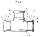
- FIG. 1 shows a top view on the left half of the figure and a longitudinal section on the right half of the picture through a pressable fitting according to the invention, which in this exemplary embodiment is designed as a T-piece 1 with the same nominal size for the outlet as for the through pipe.
- the area characterizing the type of fitting (base body 2), ie in this case the T-branch is, for example, a cast part, which in this exemplary embodiment is firmly connected to three identically designed standardized connecting pieces 3, 3 ', 3 ⁇ .
- the connector 3 'connected to the outlet would be different in its dimensions from those 3.3' which are connected to the through-pipe.
- the standardized connector 3.3 ', 3 ⁇ like the already known press fitting, has a bulge-like end 4,4', 4 ⁇ , in the cavity of which a round sealing ring 5.5 ⁇ is arranged.
- a cylindrically shaped region 6,6', 6 ⁇ which at the end acts as a stop for the insertable smooth-ended tube (not shown here) bead-shaped depression 7,7 ', 7th ⁇ is provided.
- the recess 7,7 ', 7 ⁇ merges into a sleeve-like extension 8,8 ⁇ , which can be inserted into a corresponding recess of the base body 2.
- the inserted in the base body 2 connector 3.3 ', 3 ⁇ is for example soldered to the base body 2.
- This type of connection technology will preferably be used in a connector made of carbon steel 3,3 ', 3 ⁇ . It could also be a high-strength adhesive bond.
- the sleeve-like extension 8,8 ' is matched with its dimensions to the dimensions of the recess of the base body 2 that a smooth connection is created on the inside.
- the compression of the connector 3.3 ', 3 ⁇ with the tube, not shown here, is carried out in the already known manner by means of an attached pressing tool, also not shown here.
- the diameter of the bead-like end 4,4 ', 4 ⁇ is reduced and the cavity in the bead-like end 4,4', 4 ⁇ is reduced so that the enclosed sealing ring 5.5 ⁇ is elastically deformed and thus achieves the sealing effect becomes.
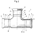
- Figure 2 shows the same top view and the same longitudinal section of another embodiment for the pressable fitting according to the invention.
- the same markings were used for the same parts.
- the difference to Figure 1 is that the standardized connectors 3,3 ', 3 ⁇ are connected to the somewhat differently shaped base body 9 via a weld 10,10', 10 ⁇ .
- This type of connection will preferably be used for fittings made of stainless steel 3,3 ', 3 ⁇ .
- This type of connection also ensures that a smooth, flush inner transition is created at the connection point.
- the other type of connection entails that the outer dimensions of the T-piece are somewhat larger in comparison to the exemplary embodiment shown in FIG. 1.
Description
- Die Erfindung betrifft einen verpreßbaren Fitting zur Herstellung einer unlösbaren, dichten Verbindung von Rohren.
- Das Preßfitting-System für die Hausinstallation aus C-Stahl oder hochlegiertem Stahl ist bekannt (siehe Prospekt der Mannesmann Edelstahlrohr GmbH bzw DE-A-2719882). Kernstück dieses Systems ist ein aus einem Rohrabschnitt hergestellter verformbarer Preßfitting, der je nach Ausbildung als Bogen oder T-Stück oder Reduzierstück mindestens ein hakenförmig und wulstartig ausgebildetes, einen Dichtring aufnehmendes Ende aufweist und daran sich ein in Längsrichtung erstreckender zylindrisch ausgebildeter Bereich anschließt. Am Ende der Erstreckung dieses zylindrischen Bereiches ist eine radial nach innen sich erstreckende sickenförmige Vertiefung angebracht, die als Anschlag für das einschiebbare glattendige Rohr dient. Mittels einer Betätigungsvorrichtung die mit einer gelenkig angeordneten Backen aufweisenden Haltevorrichtung verbunden ist, wird das wulstartige Ende plastisch und der eingeschlossene Dichtring elastisch verformt. Zusätzlich wird mit dem gleichen Preßvorgang im zylindrischer Bereich des Fittings in unmittelbarer Nähe des wulstartigen Endes eine sickenförmige Vertiefung angepreßt, die auch das darunterliegende eingeschobene Rohr mit erfaßt. Der elastisch verformte Dichtring übernimmt bei diesem Verbindungssystem die Dichtfunktion, während die angepreßte sickenförmige Vertiefung die durch den Innendruck entstehenden Längskräfte aufnimmt.
- Nachteilig bei diesem System ist, daß der Preßfitting wegen der hohen Anforderung bezüglich der Oberfläche und der Abmessungstoleranzen aus einem Abschnitt eines speziell hergestellten Rohres unter Anwendung mehrerer Umformschritte gewonnen wird. Das Ausgangsrohr ist üblicherweise ein nahtloses oder längsnahtgeschweißtes Rohr, das nach der Kaltverformung einer Wärmebehandlung unterzogen wird. Dieses speziell hergestellte Rohr weist enge Toleranzen und eine hohe Oberflächengüte auf. Um von diesem Rohr ein Preßfitting herzustellen, wird das Ausgangsrohr in Abschnitte zerteilt und durch Anwendung mehrerer Umformschritte, z. B. Einziehen, Bördeln, Drücken, die gewünschte endgültige Querschnittsform erzeugt. Da das Ausgangsprodukt schon relativ hochwertig ist, ist auch der daraus hergestellte Preßfitting relativ teuer.
- Aufgabe der Erfindung ist es, einen verpreßbaren Fitting zu schaffen, der unter Beibehaltung der bekannten schnellen Verbindungstechnik kostengünstiger herstellbar ist.
- Diese Aufgabe wird durch die Merkmale des Anspruches 1 angegebene Mittel gelöst. Vorzugsweise Ausgestaltungen ergeben sich aus den Unteransprüchen.
- Der Vorteil des vorgeschlagenen verpreßbaren Fittings ist darin zu sehen, daß der den Typ des Fittings charakterisierende Bereich, (Grundkörper) z. B. Bogen, T-Abzweig, reduzierender Übergang, aus einem metallischen oder nichtmetallischen Werkstoff gegossen oder gepreßt und der so hergestellte Grundkörper mit einem standardisierten Anschlußstück fest verbunden wird. Im Sinne einer möglichst kostengünstigen Lösung wird weiterbildend vorgeschlagen, den Grundkörper aus einfachem oder höherwertigem Grauguß herzustellen. Eine andere Möglichkeit besteht darin, einen verpreßbaren Kunststoff mit oder ohne verstärkende Fasereinlage für die Herstellung des Grundkörpers zu verwenden. Das standardisierte Anschlußstück weist wie der bereits bekannte Preßfitting ein wulstartig ausgebildetes, einen Runddichtring aufnehmendes Ende und einen dazu anschließenden zylindrisch ausgebildeten Bereich auf, der am Ende mit einer als Anschlag für das einschiebbare glattendige Rohr wirkenden sickenförmigen Vertiefung versehen ist. Die Verbindung zwischen Grundkörper und Anschlußstück erfolgt je nach Werkstoffpaarung durch Löten oder Schweißen oder durch Verkleben in der Weise, daß die Bohrung des Anschlußstückes glattbündig in die Bohrung des Grundkörpers übergeht. Dadurch wird verhindert, daß durch Wirbelbildungen an der Verbindungsstelle unzulässig hohe Strömungsverluste entstehen.
* (d.h. einer Verringerung des lichten Innendurchmessers) - Da unabhängig vom Typ des Fittings die Anschlußstücke standardisiert sind, ergeben sich für gleiche Nennabmessungen entsprechend hohe Stückzahlen, die die Kosten weiter senken. Da auch die Grundkörper als Massenprodukt erheblich billiger sind als ein entsprechendes Rohrelement, werden die Mehrkosten für die Verbindung von Grundkörper und Anschlußstück bzw. Anschlußstücken mehr als kompensiert. Ein weiterer Vorteil ergibt sich dadurch, daß das Anschlußstück durch Stanzen und Tiefziehen auch aus einem ebenen Blech herstellbar ist und die Rohrherstellung als Ausgangsprodukt für den Fitting entfallen kann.
- Damit die mit steigenden Innendrücken in Axialrichtung wirkenden Kräfte sicher aufgenommen werden können, wird weiterbildend vorgeschlagen, zusätzlich zu der den einen Dichtring enthaltenen Bereich des Anschlußstückes auch Abschnitte des sich anschließenden zylindrischen Bereiches mit dem eingeschobenen Rohr zu verpressen, um damit die mechanische Verklammerung zu verbessern.
- Der vorgeschlagene verpreßbare Fitting ist vorzugsweise geeignet für die Verbindung von handelsüblichen Leitungsrohren im Abmessungsbereich von 10 bis 100 mm mit Innendrücken je nach Nennweite bis zu 100 bar, wobei auch noch größere Nennweiten mit diesem Verbindungssystem beherrschbar sind.
- In der Zeichnung wird anhand zweier Ausführungsbeispiele der erfindungsgemäße verpreßbare Fitting näher erläutert.
- Es zeigen:
- Figur 1
- hälftig eine Draufsicht und hälftig einen Längsschnitt durch einen erfindungsgemäßen verpreßbaren Fitting
- Figur 2
- wie Fig. 1, jedoch eine andere Ausführungsform
- Figur 1 zeigt auf der linken Bildhälfte eine Draufsicht und auf der rechten Bildhälfte einen Längsschnitt durch einen erfindungsgemäßen verpreßbaren Fitting, der in diesem Ausführungsbeispiel als T-Stück 1 mit gleicher Abmessungsnennweite für den Abgang wie für das Durchgangsrohr ausgebildet ist. Der den Typ des Fittings charakterisierende Bereich, (Grundkörper 2) d. h. in diesem Falle der T-Abzweig ist beispielsweise ein Gußteil, das in diesem Ausführungsbeispiel mit drei gleich ausgebildeten standardisierten Anschlußstücken 3,3′,3˝ fest verbunden ist.
- Im Falle eines T-Stückes 1 mit reduziertem Abgang wäre das mit dem Abgang verbundene Anschlußstück 3˝ in seinen Abmessungen verschieden von denen 3,3′, die mit dem Durchgangsrohr verbunden sind.
- Das standardisierte Anschlußstück 3,3′,3˝ weist wie der bereits bekannte Preßfitting ein wulstartig ausgebildetes Ende 4,4′,4˝ auf, in dessen Hohlraum ein Runddichtring 5,5˝ angeordnet ist. An diesem Ende 4,4′,4˝ schließt ein zylindrisch ausgebildeter Bereich 6,6′,6˝ an, der am Ende mit einer als Anschlag für das einschiebbare glattendige Rohr (hier nicht dargestellt) wirkenden sickenförmigen Vertiefung 7,7′,7˝ versehen ist. Die Vertiefung 7,7′,7˝ geht über in eine muffenartige Verlängerung 8,8˝, die in eine entsprechende Ausdrehung des Grundkörpers 2 einschiebbar ist. Das in den Grundkörper 2 eingeschobene Anschlußstück 3,3′,3˝ wird beispielsweise mit dem Grundkörper 2 verlötet. Diese Art der Verbindungstechnik wird man vorzugsweise bei einem aus Kohlenstoffstahl angefertigten Anschlußstück 3,3′,3˝ anwenden. Es könnte ebenso gut auch eine hochfeste Klebeverbindung sein.
- Die muffenartige Verlängerung 8,8˝ ist mit ihren Maßen so auf die Maße der Ausdrehung des Grundkörpers 2 abgestimmt, daß innen eine glattbündige Verbindung entsteht. Die Verpreßung des Anschlußstückes 3,3′,3˝ mit dem hier nicht dargestellten Rohr erfolgt in der bereits bekannten Weise mittels eines angesetzten, hier ebenfalls nicht dargestellten Preßwerkzeuges. Bei der Verpressung wird der Durchmesser des wulstartig ausgebildeten Endes 4,4′,4˝ verringert und der Hohlraum in dem wulstartigen Ende 4,4′,4˝ so verkleinert, daß der eingeschlossene Runddichtring 5,5˝ elastisch verformt und damit die Dichtwirkung erzielt wird.
- Figur 2 zeigt dieselbe Draufsicht und den gleichen Längsschnitt eines anderen Ausführungsbeispieles für den erfindungsgemäßen verpreßbaren Fitting. Dabei wurden für gleiche Teile die gleichen Kennzeichen verwendet. Der Unterschied zu Figur 1 besteht darin, daß die standardisierten Anschlußstücke 3,3′,3˝ mit dem etwas anders geformten Grundkörper 9 über eine Schweißnaht 10,10′,10˝ miteinander verbunden sind. Diese Art der Verbindung wird man vorzugsweise für aus Edelstahl gefertigte Anschlußstücke 3,3′,3˝ anwenden. Auch bei dieser Art der Verbindung wird dafür gesorgt, daß an der Verbindungsstelle ein glattbündiger innerer Übergang entsteht. Die andere Art der Verbindung bringt es mit sich, daß die äußeren Abmaße des T-Stückes etwas größer sind im Vergleich zu dem in Figur 1 dargestellten Ausführungsbeispiel.
Claims (11)
- Verpreßbarer Fitting (1) zur Herstellung einer unlösbaren, dichten Verbindung von Rohren mit einem den Typ des Fittings (1) charakterisierenden Bereich, der als ein aus einem metallischen oder nichtmetallischen Werkstoff hergestellter gegossener oder gepreßter Grundkörper (2,9) ausgebildet und mit einem aus Blech hergestellten standardisierten Anschlußstück (3,3′,3˝) fest verbunden ist, wobei dieses Anschlußstück (3,3′,3˝) ein hakenförmig und wulstartig ausgebildetes, einen Runddichtring (5,5˝) aufnehmendes Ende (4,4′,4˝) und einen daran anschließenden zylindrisch ausgebildeten Bereich (6,6′,6˝) aufweist und am Ende mit einer als Anschlag für das einschiebbar glattendige Rohr wirkenden sickenförmigen Vertiefung (7,7′,7˝) versehen ist.
- Verpreßbarer Fitting nach Anspruch 1,
dadurch gekennzeichnet,
daß die Verbindung von Grundkörper (2) und Anschlußstück (3,3′,3˝) eine Lötnaht aufweist. - Verpreßbarer Fitting nach Anspruch 1,
dadurch gekennzeichnet,
daß die Verbindung von Grundkörper (9) und Anschlußstück (3,3′,3˝) eine Schweißnaht (10,10′,10˝) aufweist. - Verpreßbarer Fitting nach Anspruch 1,
dadurch gekennzeichnet,
daß Grundkörper (2,9) und Anschlußstück (3,3′,3˝) miteinander verklebt sind. - Verpreßbarer Fitting nach einem der Ansprpüche 1 bis 4,
dadurch gekennzeichnet,
daß das Anschlußstück (3,3′,3˝) aus einem ebenen Blechabschnitt hergestellt wird. - Verpreßbarer Fitting nach einem der Ansprüche 1 bis 4,
dadurch gekennzeichnet,
daß das Anschlußstück (3,3′,3˝) aus einem glatten Rohrabschnitt hergestellt wird. - Verpreßbarer Fitting nach einem der Ansprüche 1 bis 6,
dadurch gekennzeichnet,
daß zusätzlich auch Abschnitte des an das wulstartig ausgebildete Ende (4,4′,4˝) sich anschließenden zylindrischen Bereiches (6,6′,6˝) mit dem Rohr verpreßt wird. - Verpreßbarer Fitting nach einem der Ansprüche 1 bis 7,
dadurch gekennzeichnet,
daß im Bereich der Verbindungsstelle die Bohrung des Anschlußstückes (3,3′,3˝) glattbündig in die Bohrung des Grundkörpers (2,9) übergeht. - Verpreßbarer Fitting nach einem der Ansprüche 1 bis 8,
dadurch gekennzeichnet,
daß der Grundkörper (2, 9) ein Graugußteil ist. - Verpreßbarer Fitting nach einem der Ansprüche 1 bis 8,
dadurch gekennzeichnet,
daß der Grundkörper (2, 9) ein Preßteil aus Kunststoff ist. - Verpreßbarer Fitting nach Anspruch 10,
dadurch gekennzeichnet,
daß das Preßteil mit Fasern verstärkt ist.
Applications Claiming Priority (2)
| Application Number | Priority Date | Filing Date | Title |
|---|---|---|---|
| DE3919496A DE3919496C1 (de) | 1989-06-12 | 1989-06-12 | |
| DE3919496 | 1989-06-12 |
Publications (2)
| Publication Number | Publication Date |
|---|---|
| EP0403037A1 EP0403037A1 (de) | 1990-12-19 |
| EP0403037B1 true EP0403037B1 (de) | 1993-03-31 |
Family
ID=6382751
Family Applications (1)
| Application Number | Title | Priority Date | Filing Date |
|---|---|---|---|
| EP90250133A Expired - Lifetime EP0403037B1 (de) | 1989-06-12 | 1990-05-23 | Verpressbarer Fitting |
Country Status (9)
| Country | Link |
|---|---|
| US (1) | US5090743A (de) |
| EP (1) | EP0403037B1 (de) |
| JP (1) | JPH03121394A (de) |
| AT (1) | ATE87722T1 (de) |
| DE (2) | DE3919496C1 (de) |
| DK (1) | DK0403037T3 (de) |
| ES (1) | ES2040038T3 (de) |
| FI (1) | FI91668C (de) |
| NO (1) | NO301850B1 (de) |
Families Citing this family (45)
| Publication number | Priority date | Publication date | Assignee | Title |
|---|---|---|---|---|
| DE9104147U1 (de) * | 1991-04-04 | 1991-07-04 | Mannesmann Ag, 4000 Duesseldorf, De | |
| DE4204430A1 (de) * | 1992-02-14 | 1993-08-19 | Unit Verwaltungsgesellschaft M | Adaptierbare anschlussvorrichtung fuer rohre |
| US5464257A (en) * | 1994-10-31 | 1995-11-07 | The Harrington Corporation | Coupling for joining pipe fittings having offset lug restraints |
| USD377829S (en) * | 1994-11-09 | 1997-02-04 | Lindab A/S | Component for a ventilation duct system |
| DE19747931C1 (de) * | 1997-10-30 | 1999-07-08 | Lemfoerder Metallwaren Ag | Kugelgelenk |
| DE19820501A1 (de) * | 1998-05-07 | 1999-11-18 | Stefan Nau Gmbh & Co | System zur Verbindung von Leitungs- und/oder Armaturenteilen bei Heizungs- oder Sanitäranlagen |
| DE19833769A1 (de) * | 1998-07-17 | 2000-01-20 | Mannesmann Ag | Verfahren zur Herstellung eines verpreßbaren Fittings oder Armatur aus Metall |
| US6202284B1 (en) * | 1998-11-18 | 2001-03-20 | John Joblin | Pipe fitting |
| US6199589B1 (en) | 1999-01-18 | 2001-03-13 | Lincoln Brass Works, Inc. | Staked dual valve assembly |
| DE19901990C2 (de) * | 1999-01-20 | 2001-03-29 | Interforge Klee Gmbh | Pressfitting |
| DE10029479C2 (de) * | 1999-07-22 | 2003-02-13 | Mapress Gmbh & Co Kg | Verfahren zur Herstellung eines metallischen Pressfittingelementes |
| EP1070896B1 (de) | 1999-07-22 | 2005-06-15 | Geberit Mapress GmbH | Verfahren zur Herstellung eines metallischen Pressfittingelementes |
| US6523261B1 (en) | 1999-07-22 | 2003-02-25 | Mapress Gmbh & Co. Kg | Method of making a metallic press fitting element |
| DE19948142A1 (de) * | 1999-09-28 | 2001-04-19 | Mapress Gmbh & Co Kg | Verfahren zur Herstellung eines Preßfittings |
| US6318761B1 (en) | 1999-11-26 | 2001-11-20 | Duane D. Robertson | Replacement fitting for rigid, plastic pipes |
| IT1314898B1 (it) * | 2000-06-27 | 2003-01-16 | Itap Spa | Raccordo a compressione per tubi |
| USD681883S1 (en) | 2001-08-01 | 2013-05-07 | Rick Meritt Investments, Ltd. | Wildlife feeder |
| USD603104S1 (en) | 2001-08-01 | 2009-10-27 | Rick Meritt Investments, Ltd. | Dual animal feeder |
| USD622453S1 (en) | 2001-08-01 | 2010-08-24 | Rick Meritt Investments, Ltd. | Animal feeder |
| USD629975S1 (en) | 2001-08-01 | 2010-12-28 | Rick Meritt Investments, Ltd. | Feeding tube |
| US6920841B2 (en) | 2001-08-01 | 2005-07-26 | Rick Meritt | Unitary construction animal feeder and method for manufacture |
| EP1281456A3 (de) * | 2001-08-03 | 2004-05-12 | Mapress GmbH & Co. KG | Verfahren zur Herstellung eines einteiligen Pressfittings aus Metall |
| DE10145179C1 (de) * | 2001-09-07 | 2003-01-16 | Mapress Gmbh & Co Kg | Pressfitting aus Metall |
| DE10149381A1 (de) * | 2001-10-06 | 2003-05-08 | Daimler Chrysler Ag | Verfahren zur Herstellung eines Abzweigrohres |
| US7910047B2 (en) * | 2002-09-26 | 2011-03-22 | Lancer Partnership, Ltd. | Through fittings and a method for gas assist molding of through fittings |
| FR2871713B1 (fr) * | 2004-06-21 | 2006-08-25 | Renault Sas | Installation d'application de peinture automobile et procede utilisant l'installation |
| FR2873314A1 (fr) * | 2004-07-23 | 2006-01-27 | Renault Sas | Agencement pour le raccordement par soudage de deux tubes |
| DE102005014940B4 (de) | 2005-04-01 | 2008-07-24 | Viega Gmbh & Co. Kg | Fitting und Verfahren zur Herstellung eines Fittings |
| US7686346B1 (en) * | 2006-07-21 | 2010-03-30 | Elkhart Products Corporation | Transition tee coupling |
| ITMI20062078A1 (it) * | 2006-10-30 | 2008-04-30 | Afl S P A | Raccordo metallico |
| ES2342863B1 (es) * | 2007-05-14 | 2011-05-03 | Uralita Sistemas De Tuberias, S.A. | Sistema de saneamiento. |
| US7846573B2 (en) * | 2007-06-01 | 2010-12-07 | Cobasys, Llc | Coolant manifold |
| US8113550B2 (en) | 2007-12-10 | 2012-02-14 | Nibco Inc. | Connection with tail piece for a press-fitting |
| US7987690B2 (en) * | 2008-01-04 | 2011-08-02 | Cerro Flow Products Llc | Fluid conduits with integral end fittings and associated methods of manufacture and use |
| US7942456B2 (en) * | 2008-01-04 | 2011-05-17 | Cerro Flow Products, Inc. | Fluid conduits with integral end fittings and associated methods of manufacture and use |
| JP5352275B2 (ja) * | 2009-02-24 | 2013-11-27 | 株式会社ケーヒン・サーマル・テクノロジー | 熱交換器用接続装置 |
| USD647253S1 (en) | 2011-02-21 | 2011-10-18 | Rick Meritt Investments, Ltd. | Wildlife feeder |
| CN103511778A (zh) * | 2013-09-17 | 2014-01-15 | 梁招仙 | 一种立体三通内接头 |
| CN103511777A (zh) * | 2013-09-17 | 2014-01-15 | 梁招仙 | 一种立体三通外接头 |
| AU363260S (en) | 2015-07-03 | 2015-08-11 | Vinidex Pty Ltd | A reinforcing collar for a pipe fitting |
| USD805165S1 (en) * | 2015-09-01 | 2017-12-12 | North American Specialty Products Llc | Tee coupling |
| USD789496S1 (en) * | 2015-09-21 | 2017-06-13 | Whippet Innovations, LLC | Garden valve mount |
| KR102405086B1 (ko) * | 2015-09-29 | 2022-06-02 | 미라이얼 가부시키가이샤 | 수지제 관 이음매 |
| US11441716B2 (en) | 2015-10-28 | 2022-09-13 | Miraial Co., Ltd. | Resin pipe joint, piping, and piping production method |
| KR101979303B1 (ko) * | 2017-11-29 | 2019-05-15 | 승진산업 (주) | 배관 모듈 |
Family Cites Families (14)
| Publication number | Priority date | Publication date | Assignee | Title |
|---|---|---|---|---|
| US1059438A (en) * | 1912-07-10 | 1913-04-22 | Bridgeport Brass Co | Pipe-coupling. |
| US1850049A (en) * | 1932-01-29 | 1932-03-15 | Jr Edward S Cornell | Pipe fitting and method of making the same |
| US2005969A (en) * | 1933-03-10 | 1935-06-25 | American Radiator & Standard | Pipe fitting |
| GB423334A (en) * | 1933-03-18 | 1935-01-30 | American Radiator Co | Improvement in methods of producing hollow metal bodies such as pipe joints |
| US2398788A (en) * | 1944-01-31 | 1946-04-23 | Maremont Automotive Products I | Muffler |
| CH399098A (de) * | 1958-10-01 | 1966-03-31 | Aga Platforadling Ag | Rohrverbindung |
| JPS4983022A (de) * | 1972-12-18 | 1974-08-09 | ||
| US3976314A (en) * | 1975-01-03 | 1976-08-24 | Paul M. Hankison | Tube coupler |
| DE2719882A1 (de) * | 1977-04-29 | 1978-11-02 | Mannesmann Roehren Werke Ag | Rohrverbindung fuer leitungsrohre |
| US4620729A (en) * | 1985-03-28 | 1986-11-04 | Tru-Fit Mfg., Inc. | Round pipe starter fitting |
| US4776616A (en) * | 1986-05-26 | 1988-10-11 | Usui Kokusai Sangyo Kabushiki Kaisha | Coupling |
| JPH0790741B2 (ja) * | 1986-09-03 | 1995-10-04 | ダイキヨ−・ベバスト株式会社 | ウエザ−ストリツプの接着方法 |
| DD259662A1 (de) * | 1987-04-09 | 1988-08-31 | Geraete & Regler Werke Veb | Fuegestelle an rohren aus stahl |
| US4893848A (en) * | 1988-11-08 | 1990-01-16 | Winzeler Stamping Company | Hose coupling |
-
1989
- 1989-06-12 DE DE3919496A patent/DE3919496C1/de not_active Expired - Lifetime
-
1990
- 1990-05-23 DK DK90250133.7T patent/DK0403037T3/da active
- 1990-05-23 AT AT90250133T patent/ATE87722T1/de not_active IP Right Cessation
- 1990-05-23 DE DE9090250133T patent/DE59001103D1/de not_active Expired - Fee Related
- 1990-05-23 EP EP90250133A patent/EP0403037B1/de not_active Expired - Lifetime
- 1990-05-23 ES ES199090250133T patent/ES2040038T3/es not_active Expired - Lifetime
- 1990-06-05 FI FI902793A patent/FI91668C/fi not_active IP Right Cessation
- 1990-06-11 NO NO902587A patent/NO301850B1/no not_active IP Right Cessation
- 1990-06-12 US US07/537,443 patent/US5090743A/en not_active Expired - Fee Related
- 1990-06-12 JP JP2153822A patent/JPH03121394A/ja active Pending
Also Published As
| Publication number | Publication date |
|---|---|
| FI902793A0 (fi) | 1990-06-05 |
| NO902587D0 (no) | 1990-06-11 |
| NO301850B1 (no) | 1997-12-15 |
| DK0403037T3 (da) | 1993-08-09 |
| ATE87722T1 (de) | 1993-04-15 |
| ES2040038T3 (es) | 1993-10-01 |
| DE59001103D1 (de) | 1993-05-06 |
| DE3919496C1 (de) | 1990-07-05 |
| NO902587L (no) | 1990-12-13 |
| EP0403037A1 (de) | 1990-12-19 |
| FI91668B (fi) | 1994-04-15 |
| JPH03121394A (ja) | 1991-05-23 |
| US5090743A (en) | 1992-02-25 |
| FI91668C (fi) | 1994-07-25 |
Similar Documents
| Publication | Publication Date | Title |
|---|---|---|
| EP0403037B1 (de) | Verpressbarer Fitting | |
| DE3602499C2 (de) | ||
| EP0912854B1 (de) | Rohrverbindung | |
| DE10333721B4 (de) | Kraftstoffverteilerleiste mit einem Anschlussstück | |
| DE102007021846B4 (de) | Verbindung für Leitungen und Verfahren zu deren Herstellung | |
| EP0932786B1 (de) | Rohrverbindung | |
| DE19536598C2 (de) | Rohrverbindung | |
| DE19840668C1 (de) | Rohrverbindung | |
| EP1064488B1 (de) | Rohrverbindung | |
| DE3834353C1 (en) | Press fitting | |
| DE10002916C1 (de) | Pressfittingelement | |
| DE10029480C2 (de) | Verfahren zur Herstellung eines metallischen Pressfittingelementes | |
| EP1026431B1 (de) | Rohrpressverbindung | |
| EP1331427B1 (de) | Fitting oder Armatur zur Herstellung einer Pressverbindung mit einem eingesteckten Rohrende | |
| DE10004837C1 (de) | Rohrpressverbindung | |
| WO2000028250A1 (de) | Rohrpressverbindung | |
| DE19930549C1 (de) | Rohrverbindung | |
| DE102004041478B4 (de) | Schlauchnippel | |
| DE102019118284A1 (de) | Dünnwandiges Bauteil mit Anschlusseinrichtung und Verfahren zu dessen Herstellung | |
| DE10037436A1 (de) | Pressfittingelement | |
| DE19948142A1 (de) | Verfahren zur Herstellung eines Preßfittings | |
| WO2003014611A1 (de) | Verfahren zur herstellung eines metallischen pressfittingelementes | |
| EP0879984A2 (de) | Anschlussarmatur für Schläuche | |
| EP1023953A2 (de) | Rohrpressverbindung | |
| DE102004052123A1 (de) | Rohrpressverbindung |
Legal Events
| Date | Code | Title | Description |
|---|---|---|---|
| PUAI | Public reference made under article 153(3) epc to a published international application that has entered the european phase |
Free format text: ORIGINAL CODE: 0009012 |
|
| 17P | Request for examination filed |
Effective date: 19901002 |
|
| AK | Designated contracting states |
Kind code of ref document: A1 Designated state(s): AT BE CH DE DK ES FR GB GR IT LI LU NL SE |
|
| 17Q | First examination report despatched |
Effective date: 19910723 |
|
| GRAA | (expected) grant |
Free format text: ORIGINAL CODE: 0009210 |
|
| AK | Designated contracting states |
Kind code of ref document: B1 Designated state(s): AT BE CH DE DK ES FR GB GR IT LI LU NL SE |
|
| REF | Corresponds to: |
Ref document number: 87722 Country of ref document: AT Date of ref document: 19930415 Kind code of ref document: T |
|
| ET | Fr: translation filed | ||
| ITF | It: translation for a ep patent filed |
Owner name: BARZANO' E ZANARDO MILANO S.P.A. |
|
| REF | Corresponds to: |
Ref document number: 59001103 Country of ref document: DE Date of ref document: 19930506 |
|
| REG | Reference to a national code |
Ref country code: GR Ref legal event code: FG4A Free format text: 3007813 |
|
| GBT | Gb: translation of ep patent filed (gb section 77(6)(a)/1977) |
Effective date: 19930705 |
|
| REG | Reference to a national code |
Ref country code: DK Ref legal event code: T3 |
|
| REG | Reference to a national code |
Ref country code: ES Ref legal event code: FG2A Ref document number: 2040038 Country of ref document: ES Kind code of ref document: T3 |
|
| PLBE | No opposition filed within time limit |
Free format text: ORIGINAL CODE: 0009261 |
|
| STAA | Information on the status of an ep patent application or granted ep patent |
Free format text: STATUS: NO OPPOSITION FILED WITHIN TIME LIMIT |
|
| 26N | No opposition filed | ||
| EPTA | Lu: last paid annual fee | ||
| EAL | Se: european patent in force in sweden |
Ref document number: 90250133.7 |
|
| PGFP | Annual fee paid to national office [announced via postgrant information from national office to epo] |
Ref country code: GB Payment date: 20000410 Year of fee payment: 11 |
|
| PGFP | Annual fee paid to national office [announced via postgrant information from national office to epo] |
Ref country code: CH Payment date: 20000412 Year of fee payment: 11 |
|
| PGFP | Annual fee paid to national office [announced via postgrant information from national office to epo] |
Ref country code: NL Payment date: 20000417 Year of fee payment: 11 |
|
| PGFP | Annual fee paid to national office [announced via postgrant information from national office to epo] |
Ref country code: FR Payment date: 20000418 Year of fee payment: 11 Ref country code: AT Payment date: 20000418 Year of fee payment: 11 |
|
| PGFP | Annual fee paid to national office [announced via postgrant information from national office to epo] |
Ref country code: SE Payment date: 20000420 Year of fee payment: 11 |
|
| PGFP | Annual fee paid to national office [announced via postgrant information from national office to epo] |
Ref country code: DK Payment date: 20000425 Year of fee payment: 11 |
|
| PGFP | Annual fee paid to national office [announced via postgrant information from national office to epo] |
Ref country code: BE Payment date: 20000428 Year of fee payment: 11 |
|
| PGFP | Annual fee paid to national office [announced via postgrant information from national office to epo] |
Ref country code: LU Payment date: 20000515 Year of fee payment: 11 |
|
| PGFP | Annual fee paid to national office [announced via postgrant information from national office to epo] |
Ref country code: ES Payment date: 20000519 Year of fee payment: 11 |
|
| PGFP | Annual fee paid to national office [announced via postgrant information from national office to epo] |
Ref country code: GR Payment date: 20000531 Year of fee payment: 11 |
|
| PGFP | Annual fee paid to national office [announced via postgrant information from national office to epo] |
Ref country code: DE Payment date: 20010509 Year of fee payment: 12 |
|
| PG25 | Lapsed in a contracting state [announced via postgrant information from national office to epo] |
Ref country code: LU Free format text: LAPSE BECAUSE OF NON-PAYMENT OF DUE FEES Effective date: 20010523 Ref country code: GB Free format text: LAPSE BECAUSE OF NON-PAYMENT OF DUE FEES Effective date: 20010523 Ref country code: DK Free format text: LAPSE BECAUSE OF NON-PAYMENT OF DUE FEES Effective date: 20010523 Ref country code: AT Free format text: LAPSE BECAUSE OF NON-PAYMENT OF DUE FEES Effective date: 20010523 |
|
| PG25 | Lapsed in a contracting state [announced via postgrant information from national office to epo] |
Ref country code: SE Free format text: LAPSE BECAUSE OF NON-PAYMENT OF DUE FEES Effective date: 20010524 Ref country code: ES Free format text: LAPSE BECAUSE OF NON-PAYMENT OF DUE FEES Effective date: 20010524 |
|
| PG25 | Lapsed in a contracting state [announced via postgrant information from national office to epo] |
Ref country code: GR Free format text: LAPSE BECAUSE OF NON-PAYMENT OF DUE FEES Effective date: 20010531 Ref country code: BE Free format text: LAPSE BECAUSE OF NON-PAYMENT OF DUE FEES Effective date: 20010531 |
|
| PG25 | Lapsed in a contracting state [announced via postgrant information from national office to epo] |
Ref country code: LI Free format text: LAPSE BECAUSE OF NON-PAYMENT OF DUE FEES Effective date: 20010622 Ref country code: CH Free format text: LAPSE BECAUSE OF NON-PAYMENT OF DUE FEES Effective date: 20010622 |
|
| BERE | Be: lapsed |
Owner name: MANNESMANN A.G. Effective date: 20010531 |
|
| PG25 | Lapsed in a contracting state [announced via postgrant information from national office to epo] |
Ref country code: NL Free format text: LAPSE BECAUSE OF NON-PAYMENT OF DUE FEES Effective date: 20011201 |
|
| REG | Reference to a national code |
Ref country code: CH Ref legal event code: PL |
|
| GBPC | Gb: european patent ceased through non-payment of renewal fee |
Effective date: 20010523 |
|
| PG25 | Lapsed in a contracting state [announced via postgrant information from national office to epo] |
Ref country code: FR Free format text: LAPSE BECAUSE OF NON-PAYMENT OF DUE FEES Effective date: 20020131 |
|
| NLV4 | Nl: lapsed or anulled due to non-payment of the annual fee |
Effective date: 20011201 |
|
| REG | Reference to a national code |
Ref country code: DK Ref legal event code: EBP |
|
| PG25 | Lapsed in a contracting state [announced via postgrant information from national office to epo] |
Ref country code: DE Free format text: LAPSE BECAUSE OF NON-PAYMENT OF DUE FEES Effective date: 20021203 |
|
| REG | Reference to a national code |
Ref country code: ES Ref legal event code: FD2A Effective date: 20030203 |
|
| PG25 | Lapsed in a contracting state [announced via postgrant information from national office to epo] |
Ref country code: IT Free format text: LAPSE BECAUSE OF NON-PAYMENT OF DUE FEES;WARNING: LAPSES OF ITALIAN PATENTS WITH EFFECTIVE DATE BEFORE 2007 MAY HAVE OCCURRED AT ANY TIME BEFORE 2007. THE CORRECT EFFECTIVE DATE MAY BE DIFFERENT FROM THE ONE RECORDED. Effective date: 20050523 |