EP0402601A2 - Ensemble de visualisation opto-électronique - Google Patents
Ensemble de visualisation opto-électronique Download PDFInfo
- Publication number
- EP0402601A2 EP0402601A2 EP90108234A EP90108234A EP0402601A2 EP 0402601 A2 EP0402601 A2 EP 0402601A2 EP 90108234 A EP90108234 A EP 90108234A EP 90108234 A EP90108234 A EP 90108234A EP 0402601 A2 EP0402601 A2 EP 0402601A2
- Authority
- EP
- European Patent Office
- Prior art keywords
- image
- telescope
- view
- scanning
- mirror system
- Prior art date
- Legal status (The legal status is an assumption and is not a legal conclusion. Google has not performed a legal analysis and makes no representation as to the accuracy of the status listed.)
- Granted
Links
Images

Classifications
-
- G—PHYSICS
- G02—OPTICS
- G02B—OPTICAL ELEMENTS, SYSTEMS OR APPARATUS
- G02B23/00—Telescopes, e.g. binoculars; Periscopes; Instruments for viewing the inside of hollow bodies; Viewfinders; Optical aiming or sighting devices
- G02B23/02—Telescopes, e.g. binoculars; Periscopes; Instruments for viewing the inside of hollow bodies; Viewfinders; Optical aiming or sighting devices involving prisms or mirrors
-
- G—PHYSICS
- G02—OPTICS
- G02B—OPTICAL ELEMENTS, SYSTEMS OR APPARATUS
- G02B23/00—Telescopes, e.g. binoculars; Periscopes; Instruments for viewing the inside of hollow bodies; Viewfinders; Optical aiming or sighting devices
- G02B23/12—Telescopes, e.g. binoculars; Periscopes; Instruments for viewing the inside of hollow bodies; Viewfinders; Optical aiming or sighting devices with means for image conversion or intensification
-
- G—PHYSICS
- G02—OPTICS
- G02B—OPTICAL ELEMENTS, SYSTEMS OR APPARATUS
- G02B26/00—Optical devices or arrangements for the control of light using movable or deformable optical elements
- G02B26/08—Optical devices or arrangements for the control of light using movable or deformable optical elements for controlling the direction of light
- G02B26/10—Scanning systems
Definitions
- the invention relates to an opto-electronic viewing module for imaging a field of view on a monitor, in particular for military combat vehicles, of the type defined in the preamble of claim 1.
- the image scanning devices used in these optoelectronic or optronic view modules have a predetermined radiation receiving or detector area, to which the format of the image of a field of view generated by the telescope must be matched.
- the number of detector elements forming the detector surface determines the quality of the image resolution.
- Due to the focal length of the telescope, this image format specifies its field angle.
- the telescopes used here require large focal lengths, which necessarily leads to a sharp reduction in the field angle and thus the field of view.
- the field of view that can be detected with the telescope is then no longer suitable, in particular because of its smallness in relation to the overall scenario of interest not for monitoring fast-flying objects that have already left such a small field of view before they can be detected.
- the invention has for its object to provide an opto-electronic view module for very long ranges, which provides a sufficiently large field of view for visual monitoring with sufficiently high image resolution.
- the object is achieved according to the invention in an outlook assembly of the type specified in the preamble of claim 1 by the features in the characterizing part of claim 1.
- the field of view for a monitored area is composed within a very short time of a plurality of individual areas or segments, in the case of which dimensions are predefined by the telescope due to the required ranges and detailed resolution.
- the mirror system placed in front of the telescope in the direction of light incidence has a plurality of swivel positions, in each of which a segment is detected by the telescope and is imaged on the detector surface of the image scanning device.
- the mirror system reproducibly runs through the pivot positions one after the other in a predetermined sequence.
- the image of the field of view ultimately appearing on the monitor is thus composed of the majority of the segments lying horizontally next to and vertically one above the other in the surveillance area, which segments were recorded and scanned one after the other by the telescope.
- the mirror system which according to a preferred embodiment of the invention expediently consists of two mirrors lying one behind the other in the optical beam path and driven about orthogonal swivel axes, therefore requires relatively small swivel mirrors which are low in mass and therefore low in inertia and can be quickly moved and stopped again can.
- the speed of the mirror adjustment is substantially increased by the fact that the two mirrors are suddenly and possibly simultaneously transferred to a fixed predetermined position and blocked there as far as possible.
- the mirror drive for the swivel mirror system is synchronized by the control unit with the image scanning device in such a way that the mirror system has assumed its next swivel position at the beginning of every second scanning period and this is during the actual scanning phase (in the case of unidirectional image scanning devices) this maintains the sampling period without reset time) and the next sampling period is used for mirror pivoting.
- control unit synchronizes the evaluation electronics for processing the scanning signals and displaying the image of the field of view on the monitor with the image processing device in such a way that only the scanning signals from every other scanning period are used for processing for image generation.
- scanning frequency customary for image scanning devices is reduced from 50 Hz to 25 Hz, but this does not impair the quality of the image display on the monitor.
- the image scanning device to generate an image display for a second optical viewing channel in order to simultaneously display a further field of view on the same or a separate monitor.
- a second telescope and an optical coupling element are used which, during the scanning period of the image processing device in which the mirror changeover takes place, images the image generated by the second telescope on the detector surface of the image scanning device in order to scan it. In successive scanning periods of the image scanning device, an image generated by the first and second telescope is thus alternately scanned.
- the second telescope is preceded by a mirror system in the direction of beam incidence, which expediently also consists of two swivel mirrors which can be swiveled in the beam path in succession about axes orthogonal to one another, any position of the field of view in space can be adjusted by appropriate adjustment of the mirror.
- the two beam paths or optical channels of the two telescopes are expediently guided over a main mirror, so that both telescopes look in the same direction.
- the second telescope images a field of view within the field of view shown on the monitor with the first telescope, which can be placed in any position within the field of view by the upstream mirror system.
- the drive motors for the second mirror system are connected to a target tracking device, the field of view follows Movement of a selected target within the field of view.
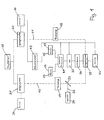
- the optoelectronic (optronic) view module shown in FIG. 1 in functional blocks has two optical beam paths or optical channels 11, 12, which are shown in broken lines in FIG. 1.
- the two optical channels 11, 12 are brought together via a main mirror 10, also called a viewing mirror, so that the same viewing direction exists for both optical channels 11, 12, which is predetermined by the position of the main mirror 10.
- the main mirror 10 is gimbaled and equipped with drive motors, angle sensors, a biaxially sensing gyro system and stabilization and drive electronics.
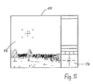
- the two optical channels 11, 12 are two separate fields of view 13, 14 on separate monitors 15, 16 or, as shown in FIG. 5, on a common monitor 17. Both fields of view 13, 14 lie within the directional range of the stabilized main mirror 10.
- each optical channel 11, 12 has an objective or telescope 18, 19 and a mirror system 20, 21 arranged upstream of the telescope 18, 19 in the direction of light incidence.
- Each mirror system 20, 21 consists of two pivoting mirrors 22, 23 and 24, 25 (FIG. 2), which are arranged one behind the other in the optical beam path and can be pivoted about orthogonal pivot axes 26, 27 and 28, 29.
- a mirroring device 20 or 21 is assigned a drive device 30 or 31, which has two separate servomotors for each pivoting mirror 22, 23 or 24, 25 (not shown here).
- the telescope 18 is designed as an IR objective, while the telescope 19 is a broadband objective, since a day vision channel 32 is also guided over it, which couples a day vision optic 24 into the optical channel 12 by means of a semitransparent divider mirror 33. If the day view channel 32 is omitted, the telescope 19 is also designed as an IR lens.
- the telescope 18 has a small magnification with a large field of view, while the telescope 19 has a large magnification with a small field of view.
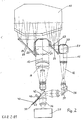
- Both optical channels 11, 12 are guided through an optical coupling member 35 and an IR eyepiece 36 to a thermal imaging device 37.
- the optical axis of the IR eyepiece 36 is aligned with the second telescope 19, while the beam path of the first telescope 18, which is parallel to this, runs through an uprighting optic 38 and a deflecting mirror 39 approximately at right angles to the optical axis of the IR eyepiece 36 .
- the optical coupling member 35 is designed as a continuously driven chopper wheel 40 which has a mirror surface 41 which extends in the direction of rotation over 180 ° and a beam passage opening 42 which extends over the further 180 °.
- the axis of rotation 43 of the chopper wheel is oriented at an acute angle to the optical axis of the IR eyepiece 36 and is arranged such that the mirror surface 41 and the beam passage opening 42 pass through the beam path between the second telescope 19 and the thermal imaging device 37 in succession during the rotation of the chopper wheel 40.
- the beam passage opening 42 is in the beam path, the image generated by the telescope 19 is imaged on the detector surface of the thermal imaging device 37, which is not shown here. If the mirror surface 41 enters the beam path, the beam path between the second telescope 19 and the IR eyepiece 36 is interrupted and the beam path of the first telescope 18 is deflected towards the IR eyepiece 36.
- the erected image generated by the first telescope 18 is thus imaged on the detector surface of the thermal imaging device 37.
- the image generated by the first telescope 18 and once the image generated by the second telescope 19 each reach the thermal imaging device 37.
- the known thermal imaging device 37 has an IR-sensitive detector surface in the form of a detector line made up of a large number of individual elements and a so-called scanner which guides the image generated by the telescopes 18, 19 horizontally across the detector line. During this scanning or scanning process, each individual element of the detector line is read out repeatedly and the electrical signals obtained, the so-called scanning signals, are sent to evaluation electronics 44.
- the scanner works unidirectionally, i.e. it always scans the image in the same direction and does a fast reverse at the end of the image scan. The position of the scanner with respect to the image to be scanned as a function of time is ideally shown in FIG. 4.
- the image is first scanned for a period of 14 ms (scanning phase a), after which the scanner is returned to its starting position in a further 6 ms (return phase b), from where the next scanning period with scanning phase is carried out a and rewind phase b of a total of 20 ms begins.
- the individual scanning signals are stored in the evaluation electronics 44 and processed in a manner known per se for image display on the monitors 15, 16.
- the display on the monitors 15, 16 takes place in the standard television standard.
- the drive device 31 for the mirror system 21 is designed such that the two pivoting mirrors 24, 25 are pivoted continuously, so that the field of view of the telescope 19 can be moved continuously within the directional range of the main mirror 10. If the drive device 31 is connected, for example, to a target tracking device, the field of view of the telescope 19 follows the movement of a selected one Target, which is shown as a magnifying glass 14 (FIG. 5) on the monitor 16 (FIG. 1) or 17 (FIG. 5) as a result of the enlargement of the telescope 19.
- a target tracking device the field of view of the telescope 19 follows the movement of a selected one Target, which is shown as a magnifying glass 14 (FIG. 5) on the monitor 16 (FIG. 1) or 17 (FIG. 5) as a result of the enlargement of the telescope 19.
- the drive device 30 for the mirror system 20 is designed such that the two pivoting mirrors 22, 23 are transferred to defined pivoting positions as far as they will go.
- the direction of incidence for the mirror system 20 has a fixed predetermined deflection angle with respect to the optical axis of the telescope 18, so that the field of view of the telescope 18 is shifted vertically and horizontally by defined steps in space.
- a control unit 45 controls the drive device 30 in such a way that the mirror system 20 assumes its individual pivot positions one after the other and in a predetermined order and remains in the pivot position assumed in each case for a predetermined period of time.
- the swivel positions of the mirror system 20 are predetermined by means of a grid and can be reproducibly approached by the drive device 30.
- the shift of the field of view of the telescope 18 in the different pivot positions of the mirror system 20 is shown schematically in FIG. 3. I denotes the position of the field of view of the telescope 18 obtained in the first swivel position of the mirror system 20, II the second, etc.
- a swivel mirror 22, 23 of the mirror system 20 is gradually tilted about its axis, and from position I to position II the vertical mirror 22, from position II to position III the horizontal mirror 23, from position III to position IV and from position IV to position V also the vertical mirror 22, from position V to position VI in turn the horizontal mirror 23 and from position VI in position I in turn the vertical mirror 22.
- the control unit 45 now synchronizes the drive device 30 for the mirror system 20 and a drive device 46 for the chopper wheel 40 and the evaluation electronics 44 each with the thermal imaging device 36.
- the drive device 30 is synchronized in such a way that the mirror system 20 at the beginning of every second scanning period of the scanner of the Thermal imaging device 35, ie every 40 ms in FIG. 4, has assumed the next swivel position and remains in this swivel position for at least 14 ms.
- the drive device 46 of the chopper wheel 40 is synchronized in such a way that the chopper wheel 40 makes one full revolution during two successive scanning periods, so that once the optical channel 11 and once the optical channel 12 is visible to the thermal imaging device 36 during successive scanning periods.
- the evaluation electronics 44 is synchronized in such a way that the scanning signals taken in successive scanning periods are each stored in separate memories and processed into two separate images.
- a large field of view 13 from the surveillance area appears on the monitor 17 with a resolution that can only be obtained with the telescope 18 only with restriction to a small field of view with the area of a segment I shown in FIG. 3 -VI would be reachable.
- the monitor 17 displays a field of view six times as large as that provided by the telescope 18 at the desired resolution. Since the image generated by the telescope 18 is scanned in every second scanning period, the Field of view 13 required twelve sampling periods of the scanner, which corresponds to a refresh rate of the field of view of 240 ms at a sampling frequency of 50 Hz.
- the second field of view 14 can be continuously displayed with a freely selectable enlargement of the field of view of the optical channel 12.
- the invention is not restricted to the exemplary embodiment described.
- a CCD camera or another electronic image scanner can be used instead of a thermal imaging device. It is also possible to use more than two optical channels in the manner described with a single image scanner to display separate images.
Applications Claiming Priority (2)
| Application Number | Priority Date | Filing Date | Title |
|---|---|---|---|
| DE3919265A DE3919265A1 (de) | 1989-06-13 | 1989-06-13 | Opto-elektronische ausblickbaugruppe |
| DE3919265 | 1989-06-13 |
Publications (3)
| Publication Number | Publication Date |
|---|---|
| EP0402601A2 true EP0402601A2 (fr) | 1990-12-19 |
| EP0402601A3 EP0402601A3 (fr) | 1991-09-25 |
| EP0402601B1 EP0402601B1 (fr) | 1995-06-28 |
Family
ID=6382656
Family Applications (1)
| Application Number | Title | Priority Date | Filing Date |
|---|---|---|---|
| EP90108234A Expired - Lifetime EP0402601B1 (fr) | 1989-06-13 | 1990-04-30 | Ensemble de visualisation opto-électronique |
Country Status (3)
| Country | Link |
|---|---|
| US (1) | US5107117A (fr) |
| EP (1) | EP0402601B1 (fr) |
| DE (2) | DE3919265A1 (fr) |
Cited By (3)
| Publication number | Priority date | Publication date | Assignee | Title |
|---|---|---|---|---|
| GB2260422A (en) * | 1991-10-09 | 1993-04-14 | Israel State | Forward looking infrared viewing apparatus |
| DE4319537A1 (de) * | 1993-06-12 | 1994-12-15 | Bodenseewerk Geraetetech | Optronisches Rundumsuchgerät |
| US5977536A (en) * | 1996-11-05 | 1999-11-02 | Bodenseewerk Geratetechnik Gmbh | All-around observation device having a rotatable objective element |
Families Citing this family (12)
| Publication number | Priority date | Publication date | Assignee | Title |
|---|---|---|---|---|
| DE4021820A1 (de) * | 1990-07-09 | 1992-01-16 | Diehl Gmbh & Co | Mine |
| US5163094A (en) * | 1991-03-20 | 1992-11-10 | Francine J. Prokoski | Method for identifying individuals from analysis of elemental shapes derived from biosensor data |
| US5991429A (en) * | 1996-12-06 | 1999-11-23 | Coffin; Jeffrey S. | Facial recognition system for security access and identification |
| JP3859479B2 (ja) * | 2001-10-17 | 2006-12-20 | 日本電気株式会社 | ボロメータ型赤外線検出器 |
| ITBO20020806A1 (it) * | 2002-12-20 | 2004-06-21 | Azionaria Costruzioni Acma Spa | Macchina etichettatrice e/o marcatrice |
| US20050062845A1 (en) * | 2003-09-12 | 2005-03-24 | Mills Lawrence R. | Video user interface system and method |
| IL162289A0 (en) * | 2004-06-01 | 2005-11-20 | Rafael Armament Dev Authority | Fast optical switching |
| JP2006013923A (ja) | 2004-06-25 | 2006-01-12 | Sony Corp | 監視装置 |
| US8339457B1 (en) * | 2007-02-28 | 2012-12-25 | Fluke Corporation | Systems and methods for time-shared memory access in a thermal imaging device |
| DE102008026027B4 (de) * | 2008-05-30 | 2010-06-17 | Lfk-Lenkflugkörpersysteme Gmbh | Verfahren zur automatisierten Lagenachregelung der Anzeige einer Wärmebildkamera |
| EP2951641B1 (fr) | 2013-01-31 | 2017-03-08 | Danmarks Tekniske Universitet | Microscope de conversion ascendante d'infrarouge |
| WO2014117781A1 (fr) * | 2013-01-31 | 2014-08-07 | Danmarks Tekniske Universitet | Télescope d'interpolation infrarouge |
Citations (4)
| Publication number | Priority date | Publication date | Assignee | Title |
|---|---|---|---|---|
| US3626091A (en) * | 1969-12-11 | 1971-12-07 | Hughes Aircraft Co | Image converter |
| WO1986003916A1 (fr) * | 1984-12-26 | 1986-07-03 | Hughes Aircraft Company | Champ multiple de detecteur de vision |
| EP0217692A1 (fr) * | 1985-08-20 | 1987-04-08 | Thomson-Csf | Dispositif d'autoalignement pour système optique d'observation d'images infrarouges |
| DE3731844A1 (de) * | 1987-09-22 | 1989-03-30 | Messerschmitt Boelkow Blohm | Optisch-mechanischer weitwinkelabtaster |
Family Cites Families (12)
| Publication number | Priority date | Publication date | Assignee | Title |
|---|---|---|---|---|
| US3088033A (en) * | 1953-08-31 | 1963-04-30 | Northrop Corp | Automatic multiple grid scanning tracker |
| US3219822A (en) * | 1961-09-01 | 1965-11-23 | Lockheed Aircraft Corp | Infrared search system |
| US3622788A (en) * | 1969-08-11 | 1971-11-23 | Hughes Aircraft Co | Target search and track system with dual mode scan capability |
| US4199785A (en) * | 1979-01-05 | 1980-04-22 | Honeywell Inc. | Electronic zoom system |
| US4574197A (en) * | 1983-03-24 | 1986-03-04 | Hughes Aircraft Company | Dual field of view sensor |
| FR2589302B1 (fr) * | 1983-10-21 | 1988-08-12 | Trt Telecom Radio Electr | Systeme de thermographie infrarouge a sensibilite amelioree par accumulation progressive des lignes de l'image |
| DE3426946C2 (de) * | 1984-07-21 | 1986-10-30 | Krauss-Maffei AG, 8000 München | Beobachtungs- und Aufklärungssystem für Fahrzeuge |
| US4806761A (en) * | 1985-04-08 | 1989-02-21 | Irvine Sensors Corporation | Thermal imager incorporating electronics module having focal plane sensor mosaic |
| US4797942A (en) * | 1987-03-02 | 1989-01-10 | General Electric | Pyramid processor for building large-area, high-resolution image by parts |
| US4912321A (en) * | 1987-03-26 | 1990-03-27 | Texas Instruments Incorporated | Radiation scanning system with pupil control |
| GB2207020B (en) * | 1987-07-08 | 1991-08-21 | Gec Avionics | Imaging system |
| US4991020A (en) * | 1989-02-17 | 1991-02-05 | Hughes Aircraft Company | Imaging system for providing separate simultaneous real time images from a singel image sensor |
-
1989
- 1989-06-13 DE DE3919265A patent/DE3919265A1/de not_active Withdrawn
-
1990
- 1990-04-30 DE DE59009316T patent/DE59009316D1/de not_active Expired - Lifetime
- 1990-04-30 EP EP90108234A patent/EP0402601B1/fr not_active Expired - Lifetime
- 1990-06-07 US US07/534,265 patent/US5107117A/en not_active Expired - Lifetime
Patent Citations (4)
| Publication number | Priority date | Publication date | Assignee | Title |
|---|---|---|---|---|
| US3626091A (en) * | 1969-12-11 | 1971-12-07 | Hughes Aircraft Co | Image converter |
| WO1986003916A1 (fr) * | 1984-12-26 | 1986-07-03 | Hughes Aircraft Company | Champ multiple de detecteur de vision |
| EP0217692A1 (fr) * | 1985-08-20 | 1987-04-08 | Thomson-Csf | Dispositif d'autoalignement pour système optique d'observation d'images infrarouges |
| DE3731844A1 (de) * | 1987-09-22 | 1989-03-30 | Messerschmitt Boelkow Blohm | Optisch-mechanischer weitwinkelabtaster |
Cited By (7)
| Publication number | Priority date | Publication date | Assignee | Title |
|---|---|---|---|---|
| GB2260422A (en) * | 1991-10-09 | 1993-04-14 | Israel State | Forward looking infrared viewing apparatus |
| FR2682491A1 (fr) * | 1991-10-09 | 1993-04-16 | Israel Defence | Appareil optique pliable. |
| US5313063A (en) * | 1991-10-09 | 1994-05-17 | State Of Israel Ministry Of Defense Armament Development Authority Rafael | Foldable optical apparatus |
| GB2260422B (en) * | 1991-10-09 | 1995-03-08 | Israel State | Foldable optical apparatus |
| DE4319537A1 (de) * | 1993-06-12 | 1994-12-15 | Bodenseewerk Geraetetech | Optronisches Rundumsuchgerät |
| EP0629890A1 (fr) * | 1993-06-12 | 1994-12-21 | Bodenseewerk Gerätetechnik GmbH | Appareil optronique de recherche panoramique |
| US5977536A (en) * | 1996-11-05 | 1999-11-02 | Bodenseewerk Geratetechnik Gmbh | All-around observation device having a rotatable objective element |
Also Published As
| Publication number | Publication date |
|---|---|
| EP0402601B1 (fr) | 1995-06-28 |
| US5107117A (en) | 1992-04-21 |
| DE3919265A1 (de) | 1990-12-20 |
| DE59009316D1 (de) | 1995-08-03 |
| EP0402601A3 (fr) | 1991-09-25 |
Similar Documents
| Publication | Publication Date | Title |
|---|---|---|
| EP0402601B1 (fr) | Ensemble de visualisation opto-électronique | |
| EP0342419B1 (fr) | Méthode pour l'observation d'une scène et dispositif associé | |
| EP1333305B1 (fr) | Système d'inspection stéréoscopique, appareil de traitement d'images stéréoscopiques et procédé de mise en oeuvre | |
| DE2331012A1 (de) | Vorrichtung zum abtasten der von einer szene ausgehenden strahlungsenergie | |
| DE3006630A1 (de) | Optische einrichtung zur erzeugung eines rasterbildes | |
| DE4335088A1 (de) | Bildaufnahmegerät | |
| DE3005427C2 (de) | Rundumsuchendes Ortungssystem | |
| DE2802441C3 (de) | Vorrichtung zur Aufnahme von Infrarotbildern mit einer Aufnahmeröhre mit pyroelektrischem Target | |
| EP0882941B1 (fr) | Autodirecteur infrarouge pour missile chercheur de cíble | |
| DE3916362A1 (de) | Opto-atmosphaerisches verbindungssystem | |
| EP1804105A2 (fr) | Système d'inspection stéréoscopique, appareil de traitement d'images stéréoscopiques et procédé de mise en oeuvre | |
| DE102018222416A1 (de) | Baugruppe für einen LiDAR-Sensor und LiDAR-Sensor | |
| DE2944161C2 (de) | Vorrichtung zur Feststellung der Scharfeinstellung eines optischen Systems | |
| EP1931133A1 (fr) | Procédé et dispositif d'acquisition optique d'une structure | |
| EP3147700B1 (fr) | Procede et dispositif d'agrandissement du champ de vision d'une camera et camera en etant equipee | |
| DE3812174A1 (de) | Sichtgerät | |
| DE3517671C2 (fr) | ||
| DE2440167B2 (de) | Einrichtung zur Auswahlsuche eines Objekts nach dessen Bild | |
| DE2041237C3 (de) | Automatische Scha rf einstellvorrichtung für Kameras oder dergleichen | |
| DE2819056A1 (de) | Hochaufloesender sensor zur erzeugung eines stabilisierten bildes vorzugsweise eines waermebildes | |
| DE3329588C1 (de) | Arbeitsverfahren einer aus Lasersender und Wärmebildgerät kombinierten Geräteanordnung sowie eine Vorrichtung hierzu | |
| DE19829982A1 (de) | Verfahren zur Ansteuerung eines Laser-Scanning-Mikroskopes mit einem kippbaren Feinfokussiertisch | |
| DE3731844A1 (de) | Optisch-mechanischer weitwinkelabtaster | |
| EP1805531A1 (fr) | Dispositif et procede pour identifier et localiser des systemes de contre-observation optique | |
| DE1473991A1 (de) | Geraet zur Kotierung und Weiterverfolgung angezielter bewegter Objekte |
Legal Events
| Date | Code | Title | Description |
|---|---|---|---|
| PUAI | Public reference made under article 153(3) epc to a published international application that has entered the european phase |
Free format text: ORIGINAL CODE: 0009012 |
|
| AK | Designated contracting states |
Kind code of ref document: A2 Designated state(s): CH DE FR GB LI NL SE |
|
| PUAL | Search report despatched |
Free format text: ORIGINAL CODE: 0009013 |
|
| AK | Designated contracting states |
Kind code of ref document: A3 Designated state(s): CH DE FR GB LI NL SE |
|
| 17P | Request for examination filed |
Effective date: 19920210 |
|
| RAP1 | Party data changed (applicant data changed or rights of an application transferred) |
Owner name: FIRMA CARL ZEISS Owner name: ATLAS ELEKTRONIK GMBH |
|
| 17Q | First examination report despatched |
Effective date: 19931220 |
|
| RAP1 | Party data changed (applicant data changed or rights of an application transferred) |
Owner name: FIRMA CARL ZEISS Owner name: STN ATLAS ELEKTRONIK GMBH |
|
| GRAA | (expected) grant |
Free format text: ORIGINAL CODE: 0009210 |
|
| AK | Designated contracting states |
Kind code of ref document: B1 Designated state(s): CH DE FR GB LI NL SE |
|
| REF | Corresponds to: |
Ref document number: 59009316 Country of ref document: DE Date of ref document: 19950803 |
|
| ET | Fr: translation filed | ||
| GBT | Gb: translation of ep patent filed (gb section 77(6)(a)/1977) |
Effective date: 19950728 |
|
| PG25 | Lapsed in a contracting state [announced via postgrant information from national office to epo] |
Ref country code: SE Effective date: 19950928 |
|
| PG25 | Lapsed in a contracting state [announced via postgrant information from national office to epo] |
Ref country code: CH Effective date: 19960430 Ref country code: LI Effective date: 19960430 |
|
| PLBE | No opposition filed within time limit |
Free format text: ORIGINAL CODE: 0009261 |
|
| STAA | Information on the status of an ep patent application or granted ep patent |
Free format text: STATUS: NO OPPOSITION FILED WITHIN TIME LIMIT |
|
| 26N | No opposition filed | ||
| REG | Reference to a national code |
Ref country code: CH Ref legal event code: PL |
|
| PGFP | Annual fee paid to national office [announced via postgrant information from national office to epo] |
Ref country code: NL Payment date: 19980430 Year of fee payment: 9 |
|
| PGFP | Annual fee paid to national office [announced via postgrant information from national office to epo] |
Ref country code: GB Payment date: 19990308 Year of fee payment: 10 |
|
| PG25 | Lapsed in a contracting state [announced via postgrant information from national office to epo] |
Ref country code: NL Free format text: LAPSE BECAUSE OF NON-PAYMENT OF DUE FEES Effective date: 19991101 |
|
| NLV4 | Nl: lapsed or anulled due to non-payment of the annual fee |
Effective date: 19991101 |
|
| PG25 | Lapsed in a contracting state [announced via postgrant information from national office to epo] |
Ref country code: GB Free format text: LAPSE BECAUSE OF NON-PAYMENT OF DUE FEES Effective date: 20000430 |
|
| GBPC | Gb: european patent ceased through non-payment of renewal fee |
Effective date: 20000430 |
|
| PGFP | Annual fee paid to national office [announced via postgrant information from national office to epo] |
Ref country code: DE Payment date: 20090422 Year of fee payment: 20 Ref country code: FR Payment date: 20090414 Year of fee payment: 20 |
|
| PG25 | Lapsed in a contracting state [announced via postgrant information from national office to epo] |
Ref country code: DE Free format text: LAPSE BECAUSE OF EXPIRATION OF PROTECTION Effective date: 20100430 |