EP0402601A2 - Optoelectronic viewing assembly - Google Patents
Optoelectronic viewing assembly Download PDFInfo
- Publication number
- EP0402601A2 EP0402601A2 EP90108234A EP90108234A EP0402601A2 EP 0402601 A2 EP0402601 A2 EP 0402601A2 EP 90108234 A EP90108234 A EP 90108234A EP 90108234 A EP90108234 A EP 90108234A EP 0402601 A2 EP0402601 A2 EP 0402601A2
- Authority
- EP
- European Patent Office
- Prior art keywords
- image
- view
- telescope
- scanning
- mirror system
- Prior art date
- Legal status (The legal status is an assumption and is not a legal conclusion. Google has not performed a legal analysis and makes no representation as to the accuracy of the status listed.)
- Granted
Links
Images

Classifications
-
- G—PHYSICS
- G02—OPTICS
- G02B—OPTICAL ELEMENTS, SYSTEMS OR APPARATUS
- G02B23/00—Telescopes, e.g. binoculars; Periscopes; Instruments for viewing the inside of hollow bodies; Viewfinders; Optical aiming or sighting devices
- G02B23/02—Telescopes, e.g. binoculars; Periscopes; Instruments for viewing the inside of hollow bodies; Viewfinders; Optical aiming or sighting devices involving prisms or mirrors
-
- G—PHYSICS
- G02—OPTICS
- G02B—OPTICAL ELEMENTS, SYSTEMS OR APPARATUS
- G02B23/00—Telescopes, e.g. binoculars; Periscopes; Instruments for viewing the inside of hollow bodies; Viewfinders; Optical aiming or sighting devices
- G02B23/12—Telescopes, e.g. binoculars; Periscopes; Instruments for viewing the inside of hollow bodies; Viewfinders; Optical aiming or sighting devices with means for image conversion or intensification
-
- G—PHYSICS
- G02—OPTICS
- G02B—OPTICAL ELEMENTS, SYSTEMS OR APPARATUS
- G02B26/00—Optical devices or arrangements for the control of light using movable or deformable optical elements
- G02B26/08—Optical devices or arrangements for the control of light using movable or deformable optical elements for controlling the direction of light
- G02B26/10—Scanning systems
Definitions
- the invention relates to an opto-electronic viewing module for imaging a field of view on a monitor, in particular for military combat vehicles, of the type defined in the preamble of claim 1.
- the image scanning devices used in these optoelectronic or optronic view modules have a predetermined radiation receiving or detector area, to which the format of the image of a field of view generated by the telescope must be matched.
- the number of detector elements forming the detector surface determines the quality of the image resolution.
- Due to the focal length of the telescope, this image format specifies its field angle.
- the telescopes used here require large focal lengths, which necessarily leads to a sharp reduction in the field angle and thus the field of view.
- the field of view that can be detected with the telescope is then no longer suitable, in particular because of its smallness in relation to the overall scenario of interest not for monitoring fast-flying objects that have already left such a small field of view before they can be detected.
- the invention has for its object to provide an opto-electronic view module for very long ranges, which provides a sufficiently large field of view for visual monitoring with sufficiently high image resolution.
- the object is achieved according to the invention in an outlook assembly of the type specified in the preamble of claim 1 by the features in the characterizing part of claim 1.
- the field of view for a monitored area is composed within a very short time of a plurality of individual areas or segments, in the case of which dimensions are predefined by the telescope due to the required ranges and detailed resolution.
- the mirror system placed in front of the telescope in the direction of light incidence has a plurality of swivel positions, in each of which a segment is detected by the telescope and is imaged on the detector surface of the image scanning device.
- the mirror system reproducibly runs through the pivot positions one after the other in a predetermined sequence.
- the image of the field of view ultimately appearing on the monitor is thus composed of the majority of the segments lying horizontally next to and vertically one above the other in the surveillance area, which segments were recorded and scanned one after the other by the telescope.
- the mirror system which according to a preferred embodiment of the invention expediently consists of two mirrors lying one behind the other in the optical beam path and driven about orthogonal swivel axes, therefore requires relatively small swivel mirrors which are low in mass and therefore low in inertia and can be quickly moved and stopped again can.
- the speed of the mirror adjustment is substantially increased by the fact that the two mirrors are suddenly and possibly simultaneously transferred to a fixed predetermined position and blocked there as far as possible.
- the mirror drive for the swivel mirror system is synchronized by the control unit with the image scanning device in such a way that the mirror system has assumed its next swivel position at the beginning of every second scanning period and this is during the actual scanning phase (in the case of unidirectional image scanning devices) this maintains the sampling period without reset time) and the next sampling period is used for mirror pivoting.
- control unit synchronizes the evaluation electronics for processing the scanning signals and displaying the image of the field of view on the monitor with the image processing device in such a way that only the scanning signals from every other scanning period are used for processing for image generation.
- scanning frequency customary for image scanning devices is reduced from 50 Hz to 25 Hz, but this does not impair the quality of the image display on the monitor.
- the image scanning device to generate an image display for a second optical viewing channel in order to simultaneously display a further field of view on the same or a separate monitor.
- a second telescope and an optical coupling element are used which, during the scanning period of the image processing device in which the mirror changeover takes place, images the image generated by the second telescope on the detector surface of the image scanning device in order to scan it. In successive scanning periods of the image scanning device, an image generated by the first and second telescope is thus alternately scanned.
- the second telescope is preceded by a mirror system in the direction of beam incidence, which expediently also consists of two swivel mirrors which can be swiveled in the beam path in succession about axes orthogonal to one another, any position of the field of view in space can be adjusted by appropriate adjustment of the mirror.
- the two beam paths or optical channels of the two telescopes are expediently guided over a main mirror, so that both telescopes look in the same direction.
- the second telescope images a field of view within the field of view shown on the monitor with the first telescope, which can be placed in any position within the field of view by the upstream mirror system.
- the drive motors for the second mirror system are connected to a target tracking device, the field of view follows Movement of a selected target within the field of view.
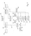
- the optoelectronic (optronic) view module shown in FIG. 1 in functional blocks has two optical beam paths or optical channels 11, 12, which are shown in broken lines in FIG. 1.
- the two optical channels 11, 12 are brought together via a main mirror 10, also called a viewing mirror, so that the same viewing direction exists for both optical channels 11, 12, which is predetermined by the position of the main mirror 10.
- the main mirror 10 is gimbaled and equipped with drive motors, angle sensors, a biaxially sensing gyro system and stabilization and drive electronics.
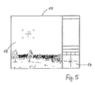
- the two optical channels 11, 12 are two separate fields of view 13, 14 on separate monitors 15, 16 or, as shown in FIG. 5, on a common monitor 17. Both fields of view 13, 14 lie within the directional range of the stabilized main mirror 10.
- each optical channel 11, 12 has an objective or telescope 18, 19 and a mirror system 20, 21 arranged upstream of the telescope 18, 19 in the direction of light incidence.
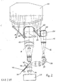
- Each mirror system 20, 21 consists of two pivoting mirrors 22, 23 and 24, 25 (FIG. 2), which are arranged one behind the other in the optical beam path and can be pivoted about orthogonal pivot axes 26, 27 and 28, 29.
- a mirroring device 20 or 21 is assigned a drive device 30 or 31, which has two separate servomotors for each pivoting mirror 22, 23 or 24, 25 (not shown here).
- the telescope 18 is designed as an IR objective, while the telescope 19 is a broadband objective, since a day vision channel 32 is also guided over it, which couples a day vision optic 24 into the optical channel 12 by means of a semitransparent divider mirror 33. If the day view channel 32 is omitted, the telescope 19 is also designed as an IR lens.
- the telescope 18 has a small magnification with a large field of view, while the telescope 19 has a large magnification with a small field of view.
- Both optical channels 11, 12 are guided through an optical coupling member 35 and an IR eyepiece 36 to a thermal imaging device 37.
- the optical axis of the IR eyepiece 36 is aligned with the second telescope 19, while the beam path of the first telescope 18, which is parallel to this, runs through an uprighting optic 38 and a deflecting mirror 39 approximately at right angles to the optical axis of the IR eyepiece 36 .
- the optical coupling member 35 is designed as a continuously driven chopper wheel 40 which has a mirror surface 41 which extends in the direction of rotation over 180 ° and a beam passage opening 42 which extends over the further 180 °.
- the axis of rotation 43 of the chopper wheel is oriented at an acute angle to the optical axis of the IR eyepiece 36 and is arranged such that the mirror surface 41 and the beam passage opening 42 pass through the beam path between the second telescope 19 and the thermal imaging device 37 in succession during the rotation of the chopper wheel 40.
- the beam passage opening 42 is in the beam path, the image generated by the telescope 19 is imaged on the detector surface of the thermal imaging device 37, which is not shown here. If the mirror surface 41 enters the beam path, the beam path between the second telescope 19 and the IR eyepiece 36 is interrupted and the beam path of the first telescope 18 is deflected towards the IR eyepiece 36.
- the erected image generated by the first telescope 18 is thus imaged on the detector surface of the thermal imaging device 37.
- the image generated by the first telescope 18 and once the image generated by the second telescope 19 each reach the thermal imaging device 37.
- the known thermal imaging device 37 has an IR-sensitive detector surface in the form of a detector line made up of a large number of individual elements and a so-called scanner which guides the image generated by the telescopes 18, 19 horizontally across the detector line. During this scanning or scanning process, each individual element of the detector line is read out repeatedly and the electrical signals obtained, the so-called scanning signals, are sent to evaluation electronics 44.
- the scanner works unidirectionally, i.e. it always scans the image in the same direction and does a fast reverse at the end of the image scan. The position of the scanner with respect to the image to be scanned as a function of time is ideally shown in FIG. 4.
- the image is first scanned for a period of 14 ms (scanning phase a), after which the scanner is returned to its starting position in a further 6 ms (return phase b), from where the next scanning period with scanning phase is carried out a and rewind phase b of a total of 20 ms begins.
- the individual scanning signals are stored in the evaluation electronics 44 and processed in a manner known per se for image display on the monitors 15, 16.
- the display on the monitors 15, 16 takes place in the standard television standard.
- the drive device 31 for the mirror system 21 is designed such that the two pivoting mirrors 24, 25 are pivoted continuously, so that the field of view of the telescope 19 can be moved continuously within the directional range of the main mirror 10. If the drive device 31 is connected, for example, to a target tracking device, the field of view of the telescope 19 follows the movement of a selected one Target, which is shown as a magnifying glass 14 (FIG. 5) on the monitor 16 (FIG. 1) or 17 (FIG. 5) as a result of the enlargement of the telescope 19.
- a target tracking device the field of view of the telescope 19 follows the movement of a selected one Target, which is shown as a magnifying glass 14 (FIG. 5) on the monitor 16 (FIG. 1) or 17 (FIG. 5) as a result of the enlargement of the telescope 19.
- the drive device 30 for the mirror system 20 is designed such that the two pivoting mirrors 22, 23 are transferred to defined pivoting positions as far as they will go.
- the direction of incidence for the mirror system 20 has a fixed predetermined deflection angle with respect to the optical axis of the telescope 18, so that the field of view of the telescope 18 is shifted vertically and horizontally by defined steps in space.
- a control unit 45 controls the drive device 30 in such a way that the mirror system 20 assumes its individual pivot positions one after the other and in a predetermined order and remains in the pivot position assumed in each case for a predetermined period of time.
- the swivel positions of the mirror system 20 are predetermined by means of a grid and can be reproducibly approached by the drive device 30.
- the shift of the field of view of the telescope 18 in the different pivot positions of the mirror system 20 is shown schematically in FIG. 3. I denotes the position of the field of view of the telescope 18 obtained in the first swivel position of the mirror system 20, II the second, etc.
- a swivel mirror 22, 23 of the mirror system 20 is gradually tilted about its axis, and from position I to position II the vertical mirror 22, from position II to position III the horizontal mirror 23, from position III to position IV and from position IV to position V also the vertical mirror 22, from position V to position VI in turn the horizontal mirror 23 and from position VI in position I in turn the vertical mirror 22.
- the control unit 45 now synchronizes the drive device 30 for the mirror system 20 and a drive device 46 for the chopper wheel 40 and the evaluation electronics 44 each with the thermal imaging device 36.
- the drive device 30 is synchronized in such a way that the mirror system 20 at the beginning of every second scanning period of the scanner of the Thermal imaging device 35, ie every 40 ms in FIG. 4, has assumed the next swivel position and remains in this swivel position for at least 14 ms.
- the drive device 46 of the chopper wheel 40 is synchronized in such a way that the chopper wheel 40 makes one full revolution during two successive scanning periods, so that once the optical channel 11 and once the optical channel 12 is visible to the thermal imaging device 36 during successive scanning periods.
- the evaluation electronics 44 is synchronized in such a way that the scanning signals taken in successive scanning periods are each stored in separate memories and processed into two separate images.
- a large field of view 13 from the surveillance area appears on the monitor 17 with a resolution that can only be obtained with the telescope 18 only with restriction to a small field of view with the area of a segment I shown in FIG. 3 -VI would be reachable.
- the monitor 17 displays a field of view six times as large as that provided by the telescope 18 at the desired resolution. Since the image generated by the telescope 18 is scanned in every second scanning period, the Field of view 13 required twelve sampling periods of the scanner, which corresponds to a refresh rate of the field of view of 240 ms at a sampling frequency of 50 Hz.
- the second field of view 14 can be continuously displayed with a freely selectable enlargement of the field of view of the optical channel 12.
- the invention is not restricted to the exemplary embodiment described.
- a CCD camera or another electronic image scanner can be used instead of a thermal imaging device. It is also possible to use more than two optical channels in the manner described with a single image scanner to display separate images.
Landscapes
- Physics & Mathematics (AREA)
- General Physics & Mathematics (AREA)
- Optics & Photonics (AREA)
- Astronomy & Astrophysics (AREA)
- Studio Devices (AREA)
- Radiation Pyrometers (AREA)
- Transforming Light Signals Into Electric Signals (AREA)
Abstract
Eine opto-elektronische Ausblickbaugruppe zur Abbildung eines Sehfelds auf einem Monitor weist ein Teleskop zur Erzeugung eines optischen Bildes des Sehfeldes, eine Bildabtastvorrichtung zum elektronischen Abtasten des optischen Bildes und eine elektronische Auswerteeinheit zur Verarbeitung der Abtastsignale und Darstellung der Abbildung auf dem Monitor auf. Zur Schaffung eines für die Überwachung ausreichend großen Sehfeldes bei großer Reichweite der Ausblickbaugruppe und ausreichender Bildauflösung ist dem Teleskop ein Spiegelsystem zur Schwenkung der Strahleinfallsrichtung in Vertikal- und Horizontalrichtung vorgeordnet. Mittels eines Antriebsrasters kann das Spiegelsystem reproduzierbar in vorgegebener Reihenfolge fest vorgebene Schwenkpositionen nacheinander durchlaufen. Die aus den einzelnen Schwenkpositionen erhaltenen Bildabtastsignale werden zu einem Sehfeld zusammengesetzt. Parallel dazu wird aus dem großen Sehfeld ein kleines Sehfeld, beliebig innerhalb des großen Sehfelds positionierbar und mit der gleichen Bildabtastvorrichtung und der Auswerteeinheit erzeugt, dargestellt. 
Description
Die Erfindung betrifft eine opto-elektronische Ausblickbaugruppe zur Abbildung eines Sehfeldes auf einem Monitor, insbesondere für militärische Kampffahrzeuge, der im Oberbegriff des Anspruchs 1 definierten Gattung.The invention relates to an opto-electronic viewing module for imaging a field of view on a monitor, in particular for military combat vehicles, of the type defined in the preamble of
Die bei diesen opto-elektronischen oder optronischen Ausblickbaugruppen verwendeten Bildabtastvorrichtungen, wie Wärmebildgeräte oder CCD-Kameras, haben eine vorgegebene Strahlungsempfangs- oder Detektorfläche, auf die das Format des vom Teleskop erzeugten Bildes eines Sehfeldes abgestimmt werden muß. Die Anzahl der die Detektorfläche bildenden Detektorelemente bestimmt die Güte der Bildauflösung. Durch dieses Bildformat ist aufgrund der Brennweite des Teleskops dessen Feldwinkel vorgegeben. Bei Ausblickbaugruppen für militärische Fahrzeuge werden hohe Reichweiten bei genügend großer Detailerkennung gefordert. Damit benötigen die hier eingesetzten Teleskope große Brennweiten, was notwendigerweise zu einer starken Verkleinerung des Feldwinkels und damit des Sehfeldes führt. Das mit dem Teleskop erfaßbare Sehfeld ist dann wegen seiner Kleinheit in Relation zu dem interessierenden Gesamtszenario für Überwachungsaufgaben nicht mehr geeignet, insbesondere nicht zur Überwachung schnell fliegender Objekte, die ein solch kleines Sehfeld bereits verlassen haben, bevor sie detektiert werden können.The image scanning devices used in these optoelectronic or optronic view modules, such as thermal imaging devices or CCD cameras, have a predetermined radiation receiving or detector area, to which the format of the image of a field of view generated by the telescope must be matched. The number of detector elements forming the detector surface determines the quality of the image resolution. Due to the focal length of the telescope, this image format specifies its field angle. For outlook assemblies for military vehicles, long ranges are required with sufficient detail recognition. The telescopes used here require large focal lengths, which necessarily leads to a sharp reduction in the field angle and thus the field of view. The field of view that can be detected with the telescope is then no longer suitable, in particular because of its smallness in relation to the overall scenario of interest not for monitoring fast-flying objects that have already left such a small field of view before they can be detected.
Der Erfindung liegt die Aufgabe zugrunde, eine opto-elektronische Ausblickbaugruppe für sehr große Reichweiten zu schaffen, die bei genügend großer Bildauflösung ein für die Sichtüberwachung ausreichend großes Sehfeld liefert.The invention has for its object to provide an opto-electronic view module for very long ranges, which provides a sufficiently large field of view for visual monitoring with sufficiently high image resolution.
Die Aufgabe ist bei einer Ausblickbaugruppe der im Oberbegriff des Anspruchs 1 angegebenen Gattung erfindungsgemäß durch die Merkmale im Kennzeichenteil des Anspruchs 1 gelöst.The object is achieved according to the invention in an outlook assembly of the type specified in the preamble of
Bei der erfindungsgemäßen optronischen Ausblickbaugruppe wird innerhalb kürzester Zeit das Sehfeld für ein überwachtes Gebiet aus einer Mehrzahl von Einzelbereichen oder Segmenten zusammengesetzt, bei der Abmessungen aufgrund der geforderten Reichweiten und Detailauflösung vom Teleskop vorgegeben sind. Das dem Teleskop in Lichteinfallsrichtung vorgesetzte Spiegelsystem hat eine Mehrzahl von Schwenkpositionen, in denen jeweils ein Segment vom Teleskop erfaßt und auf der Detektorfläche der Bildabtastvorrichtung abgebildet wird. Die Schwenkpositionen werden von dem Spiegelsystem reproduzierbar in einer vorgegebenen Reihenfolge nacheinander durchlaufen. Die auf dem Monitor letztlich erscheinende Abbildung des Sehfeldes ist damit aus der Mehrzahl der im Überwachungsgebiet horizontal neben- und vertikal übereinanderliegenden Segmenten zusammengesetzt, die zeitlich nacheinander vom Teleskop erfaßt und abgetastet worden sind.In the case of the optronic view module according to the invention, the field of view for a monitored area is composed within a very short time of a plurality of individual areas or segments, in the case of which dimensions are predefined by the telescope due to the required ranges and detailed resolution. The mirror system placed in front of the telescope in the direction of light incidence has a plurality of swivel positions, in each of which a segment is detected by the telescope and is imaged on the detector surface of the image scanning device. The mirror system reproducibly runs through the pivot positions one after the other in a predetermined sequence. The image of the field of view ultimately appearing on the monitor is thus composed of the majority of the segments lying horizontally next to and vertically one above the other in the surveillance area, which segments were recorded and scanned one after the other by the telescope.
Da die Segmente innerhalb des Sehfeldes - wie dargelegt - aus optischen Gründen relativ klein sind, brauchen auch die Spiegelflächen des Spiegelsystems nur klein zu sein. Man kommt bei dem Spiegelsystem, das gemäß einer bevorzugten Ausführungsform der Erfindung zweckmäßigerweise aus zwei im optischen Strahlengang hintereinander liegenden, um orthogonale Schwenkachsen angetriebenen Spiegeln besteht, daher mit relativ kleinen Schwenkspiegeln aus, die masse- und damit trägheitsarm sind und schnell bewegt und wieder stillgesetzt werden können. Die Schnelligkeit der Spiegeleinstellung wird wesentlich dadurch vergößert, daß die beiden Spiegel schlagartig und ggf. gleichzeitig in eine fest vorgegebene Position überführt und dort auf Anschlag blockiert werden. Im Gegensatz zu einer kontinuierlichen Verstellung der Spiegel bis zur Endposition mit Stillsetzen des Antriebs in der Endposition, wird eine sehr viel kürzere Stellzeit zum Verbringen der Schwenkspiegel von der einen in die andere Position benötigt. Infolge der geringen Trägheitsmassen schwingen die Spiegel beim Anschlag in der neuen Position nur kurzzeitig und kommen schnell zur Ruhe. Bei der erfindungsgemäßen Ausblickbaugruppe können Umschaltzeiten für die Schwenkspiegel von kleiner 26 ms realisiert werden. Legt man die für bekannte Wärmebildgeräte übliche reine Abtastzeit pro Bild von 14 ms zugrunde, so werden für die Erfassung eines Segments des Sehfeldes weniger als 40 ms benötigt. Ein z.B. aus sechs Segmenten (zwei horizontal nebeneinanderliegende Reihen von jeweils drei vertikal übereinanderliegenden Segmenten) zusammengesetztes Sehfeld wird somit in weniger als 240 ms wiederholt abgetastet, d.h. auf den aktuellen Informationsstand gebracht. Je nach der gewünschten Auffrischrate des Sehfeldes kann dieses aus mehr oder weniger vielen Segmenten zusammengesetzt werden.Since the segments within the field of view - as explained - are relatively small for optical reasons, the mirror surfaces of the mirror system need only be small. The mirror system, which according to a preferred embodiment of the invention expediently consists of two mirrors lying one behind the other in the optical beam path and driven about orthogonal swivel axes, therefore requires relatively small swivel mirrors which are low in mass and therefore low in inertia and can be quickly moved and stopped again can. The speed of the mirror adjustment is substantially increased by the fact that the two mirrors are suddenly and possibly simultaneously transferred to a fixed predetermined position and blocked there as far as possible. In contrast to a continuous adjustment of the mirrors to the end position with the drive stopping in the end position, a much shorter positioning time is required to move the swivel mirror from one position to the other. As a result of the low inertial masses, the mirrors only vibrate briefly when they stop in the new position and quickly come to rest. Switching times for the swivel mirror of less than 26 ms can be realized in the view assembly according to the invention. If the pure scanning time per image of 14 ms, which is customary for known thermal imaging devices, is used, less than 40 ms are required for the acquisition of a segment of the visual field. A field of view composed, for example, of six segments (two horizontally adjacent rows of three vertically superimposed segments) is thus repeatedly scanned in less than 240 ms, ie brought up to date. Depending on the desired refresh rate of the field of view, this can consist of more or fewer segments are put together.
Vorteilhafte Ausführungsformen der erfindungsgemäßen Ausblickbaugruppe mit zweckmäßiger Weiterbildungen und Ausgestaltungen der Erfindung ergeben sich aus den weiteren Ansprüchen.Advantageous embodiments of the outlook assembly according to the invention with expedient further developments and refinements of the invention result from the further claims.
Für bidirektionale Bildabtastvorrichtungen oder unidirektionale Bildabtastvorrichtungen mit extrem kurzen Rückstellzeiten des Scanners sind keine ausreichenden Totzeiten vorhanden, die für die Spiegelschwenkung genutzt werden könnten. In diesen Fällen ist gemäß einer bevorzugten Ausführungsform der Erfindung der Spiegelantrieb für das Schwenkspiegelsystem durch die Steuereinheit mit der Bildabtastvorrichtung derart synchronisiert, daß das Spiegelsystem jeweils mit Beginn jeder zweiten Abtastperiode seine jeweils nächste Schwenkposition eingenommen hat und diese während der eigentlichen Abtastphase (bei unidirektionalen Bildabtastvorrichtungen ist dies die Abtastperiode ohne Rückstellzeit) beibehält und die nächste Abtastperiode zur Spiegelschwenkung ausgenutzt wird. Entsprechend synchronisiert die Steuereinheit die Auswerteelektronik zur Verarbeitung der Abtastsignale und Darstellung der Abbildung des Sehfeldes auf dem Monitor mit der Bildverarbeitungsvorrichtung derart, daß nur die Abtastsignale aus jeder zweiten Abtastperiode zwecks Bildgenerierung zur Verarbeitung herangezogen werden. Bei dieser Methode wird die bei Bildabtastvorrichtungen übliche Scanfrequenz von 50 Hz auf 25 Hz reduziert, was jedoch die Qualität der Bilddarstellung auf dem Monitor nicht beeinträchtigt.For bidirectional image scanners or unidirectional image scanners with extremely short reset times of the scanner, there are insufficient dead times that could be used for mirror rotation. In these cases, according to a preferred embodiment of the invention, the mirror drive for the swivel mirror system is synchronized by the control unit with the image scanning device in such a way that the mirror system has assumed its next swivel position at the beginning of every second scanning period and this is during the actual scanning phase (in the case of unidirectional image scanning devices) this maintains the sampling period without reset time) and the next sampling period is used for mirror pivoting. Accordingly, the control unit synchronizes the evaluation electronics for processing the scanning signals and displaying the image of the field of view on the monitor with the image processing device in such a way that only the scanning signals from every other scanning period are used for processing for image generation. With this method, the scanning frequency customary for image scanning devices is reduced from 50 Hz to 25 Hz, but this does not impair the quality of the image display on the monitor.
Gemäß einer bevorzugten Ausführungsform der Erfindung werden die dadurch während der Spiegelschwenkung entstehenden Quasitotzeiten für die Bildabtastvorrichtung dazu ausgenutzt, eine Bilddarstellung für einen zweiten optischen Sichtkanal zu generieren, um damit ein weiteres Sehfeld gleichzeitig auf dem gleichen oder einem separaten Monitor darzustellen. Hierzu wird ein zweites Teleskop und ein optisches Koppelglied verwendet, das während der Abtastperiode der Bildverarbeitungsvorrichtung, in welcher die Spiegelumstellung erfolgt, das vom zweiten Teleskop erzeugte Bild auf der Detektorfläche der Bildabtastvorrichtung zu dessen Abtastung abbildet. In aufeinanderfolgenden Abtastperioden der Bildabtastvorrichtung wird damit wechselweise ein vom ersten und zweiten Teleskop erzeugtes Bild abgetastet.According to a preferred embodiment of the invention, they are thereby during the mirror pivoting resulting quasitot times are used for the image scanning device to generate an image display for a second optical viewing channel in order to simultaneously display a further field of view on the same or a separate monitor. For this purpose, a second telescope and an optical coupling element are used which, during the scanning period of the image processing device in which the mirror changeover takes place, images the image generated by the second telescope on the detector surface of the image scanning device in order to scan it. In successive scanning periods of the image scanning device, an image generated by the first and second telescope is thus alternately scanned.
Wird gemäß einer weiteren Ausführungsform der Erfindung dem zweiten Teleskop ein Spiegelsystem in Strahleinfallsrichtung vorgeordnet, das zweckmäßigerweise ebenfalls aus zwei im Strahlengang hintereinander, um zueinander orthogonalen Achsen schwenkbaren Schwenkspiegeln besteht, so kann durch entsprechende Einstellung der Spiegel jede beliebige Position des Sehfelds im Raum eingestellt werden.If, according to a further embodiment of the invention, the second telescope is preceded by a mirror system in the direction of beam incidence, which expediently also consists of two swivel mirrors which can be swiveled in the beam path in succession about axes orthogonal to one another, any position of the field of view in space can be adjusted by appropriate adjustment of the mirror.
Zweckmäßigerweise sind gemäß einer weiteren Ausführungsform der Erfindung die beiden Strahlengänge oder optischen Kanäle der beiden Teleskope über einen Hauptspiegel geführt, so daß beide Teleskope in die gleiche Richtung blicken. In diesem Fall bildet das zweite Teleskop einen Sehfeldausschnitt innerhalb des mit dem ersten Teleskop auf dem Monitor abgebildeten Sehfeldes ab, der durch das vorgeordnete Spiegelsystem in jede Position innerhalb des Sehfeldes gelegt werden kann. Bei Anschluß der Antriebsmotoren für das zweite Spiegelsystem an eine Zielverfolgungseinrichtung folgt der Sehfeldausschnitt der Bewegung eines ausgewählten Ziels innerhalb des Sehfeldes.According to a further embodiment of the invention, the two beam paths or optical channels of the two telescopes are expediently guided over a main mirror, so that both telescopes look in the same direction. In this case, the second telescope images a field of view within the field of view shown on the monitor with the first telescope, which can be placed in any position within the field of view by the upstream mirror system. When the drive motors for the second mirror system are connected to a target tracking device, the field of view follows Movement of a selected target within the field of view.
Die Erfindung ist anhand eines in der Zeichnung dargestellten Ausführungsbeispiels im nachfolgenden näher beschrieben. Es zeigen:
- Fig. 1 ein Schaltbild der Funktionsblöcke einer opto-elektronischen Ausblickbaugruppe für ein Kampffahrzeug,
- Fig. 2 eine Seitenansicht des Optikteils der Ausblickbaugruppe in Fig. 1,
- Fig. 3 eine schematische Darstellung des Sehfelds der Ausblickbaugruppe,
- Fig. 4 ein Diagramm zur Erläuterung des Abtastvorgangs einer Bildabtastvorrichtung in der Ausblickbaugruppe in Fig. 1,
- Fig. 5 eine schematische Darstellung des Bildschirms eines Monitors mit der Ausblickbaugruppe in Fig. 1 mit zwei gleichzeitig dargestellten Sehfeldern.
- 1 is a circuit diagram of the functional blocks of an opto-electronic view module for a combat vehicle,
- FIG. 2 shows a side view of the optical part of the view assembly in FIG. 1,
- 3 shows a schematic representation of the field of view of the outlook assembly,
- FIG. 4 is a diagram for explaining the scanning process of an image scanner in the outlook assembly in FIG. 1;
- Fig. 5 is a schematic representation of the screen of a monitor with the view module in Fig. 1 with two fields of view shown simultaneously.
Die in Fig. 1 in Funktionsblöcken dargestellte opto-elektronische (optronische) Ausblickbaugruppe weist zwei optische Strahlengänge oder optische Kanäle 11, 12 auf, die in Fig. 1 strichliniert dargestellt sind. Eingangsseitig sind die beiden optischen Kanäle 11, 12 über einen Hauptspiegel 10, auch Ausblickspiegel genannt, zusammengeführt, so daß für beide optischen Kanäle 11, 12 die gleiche Blickrichtung besteht, die durch die Stellung des Hauptspiegels 10 vorgegeben ist. Der Hauptspiegel 10 ist kardanisch aufgehängt und mit Antriebsmotoren, Winkelsensoren, einem zweiachsig sensierenden Kreiselsystem und einer Stabilisierungs- und Antriebselektronik versehen. aber die beiden optischen Kanäle 11, 12 sind zwei getrennte Sehfelder 13, 14 auf getrennten Monitoren 15, 16 oder gemäß Fig. 5 auf einem gemeinsamen Monitor 17 darstellbar. Beide Sehfelder 13, 14 liegen innerhalb des Richtbereichs des stabilisierten Hauptspiegels 10.The optoelectronic (optronic) view module shown in FIG. 1 in functional blocks has two optical beam paths or
Im einzelnen weist jeder optische Kanal 11, 12 ein Objektiv oder Teleskop 18, 19 und ein dem Teleskop 18, 19 in Lichteinfallsrichtung vorgeordnetes Spiegelsystem 20, 21 auf. Jedes Spiegelsystem 20, 21 besteht aus zwei schwenkspiegeln 22, 23 bzw. 24, 25 (Fig. 2), die im optischen Strahlengang hintereinander angeordnet und um orthogonale Schwenkachsen 26, 27 bzw. 28, 29 schwenkbar sind. Zum Antrieb der Schwenkspiegel 22, 23 bzw. 24, 25 ist jedem Spiegelsystem 20 bzw. 21 eine Antriebsvorrichtung 30 bzw. 31 zugeordnet, die zwei separate Stellmotoren für jeden Schwenkspiegel 22, 23 bzw. 24, 25 aufweist (hier nicht dargestellt). Das Teleskop 18 ist als IR-Objektiv ausgebildet, während das Teleskop 19 ein Breitbandobjektiv ist, da über dieses noch ein Tagsichtkanal 32 geführt ist, der mittels eines halbdurchlässigen Teilerspiegels 33 eine Tagsichtoptik 24 in den optischen Kanal 12 einkoppelt. Bei Wegfall des Tagsichtkanals 32 wird auch das Teleskop 19 als IR-Objektiv ausgebildet. Das Teleskop 18 hat eine kleine Vergrößerung mit einem großen Sehfeld, während das Teleskop 19 eine große Vergrößerung mit kleinem Sehfeld aufweist.In particular, each
Beide optischen Kanäle 11, 12 sind durch ein optisches Koppelglied 35 und ein IR-Okular 36 auf ein Wärmebildgerät 37 geführt. Wie aus Fig. 2 ersichtlich, fluchtet die optische Achse des IR-Okulars 36 mit dem zweiten Teleskop 19, während der dazu parallele Strahlengang des ersten Teleskops 18 über eine Aufrichtoptik 38 und einen Umlenkpsiegel 39 etwa rechtwinklig zur optischen Achse des IR-Okulars 36 verläuft. Das optische Koppelglied 35 ist als kontinuierlich angetriebenes Chopperrad 40 ausgebildet, das eine in Drehrichtung über 180° sich erstreckende Spiegelfläche 41 und eine über die weiteren 180° sich erstreckende Strahlendurchgangsöffnung 42 aufweist. Die Drehachse 43 des Chopperrads ist unter einem spitzen Winkel zur optischen Achse des IR-Okulars 36 ausgerichtet und so angeordnet, daß während der Rotation des Chopperrads 40 die Spiegelfläche 41 und die Strahlendurchgangsöffnung 42 nacheinander durch den Strahlengang zwischen zweitem Teleskop 19 und Wärmebildgerät 37 hindurchtreten. Solange sich die Strahlendurchgangsöffnung 42 im Strahlengang befindet, wird das vom Teleskop 19 erzeugte Bild auf der hier nicht dargestellten Detektorfläche des Wärmebildgeräts 37 abgebildet. Tritt die Spiegelfläche 41 in den Strahlengang ein, so wird der Strahlengang zwischen zweitem Teleskop 19 und IR-Okular 36 unterbrochen und der Strahlengang des ersten Teleskops 18 zum IR-Okular 36 hin umgelenkt. Damit wird das vom ersten Teleskop 18 erzeugte, aufgerichtete Bild auf der Detektorfläche des Wärmebildgeräts 37 abgebildet. Während einer vollen Umdrehung des Chopperrads 40 gelangt damit jeweils einmal das vom ersten Teleskop 18 erzeugte Bild und einmal das vom zweiten Teleskop 19 erzeugte Bild zu dem Wärmebildgerät 37.Both
Das an sich bekannte Wärmebildgerät 37 weist eine IR-empfindliche Detektorfläche in Form einer Detektorzeile aus einer Vielzahl von Einzelelementen und einen sog. Scanner auf, der das jeweils von den Teleskopen 18, 19 erzeugte Bild horizontal über die Detektorzeile führt. Während dieses Scan- oder Abtastvorgangs wird jedes Einzelelement der Detektorzeile wiederholt ausgelesen und die erhaltenen elektrischen Signale, die sog. Abtastsignale, an eine Auswerteelektronik 44 gegeben. Der Scanner arbeitet unidirektional, d.h. er tastet das Bild immer in der gleichen Richtung ab und führt am Ende der Bildabtastung einen schnellen Rücklauf aus. Die Position des Scanners bezüglich des abzutastenden Bildes in Abhängigkeit von der Zeit ist idealisiert in Fig. 4 dargestellt. Bei einer Scanfrequenz von 50 Hz erfolgt zunächst die Abtastung des Bildes während einer Zeitdauer von 14 ms (Abtastphase a), wonach in weiteren 6 ms der Rücklauf des Scanners auf seiner Ausgangsposition durchgeführt wird (Rücklaufphase b), von wo aus die nächste Abtastperiode mit Abtastphase a und Rücklaufphase b von insgesamt 20 ms beginnt. In der Auswerteelektronik 44 werden die einzelnen Abtastsignale gespeichert und zur Bilddarstellung auf den Monitoren 15, 16 in an sich bekannter Weise verarbeitet. Die Darstellung auf den Monitoren 15, 16 erfolgt in Standard-Fernsehnorm.The known
Die Antriebsvorrichtung 31 für das Spiegelsystem 21 ist so ausgebildet, daß ein stetiges Schwenken der beiden Schwenkspiegel 24, 25 erfolgt, so daß das Sehfeld des Teleskops 19 innerhalb des Richtbereichs des Hauptspiegels 10 kontinuierlich bewegt werden kann. Wird die Antriebsvorrichtung 31 z.B. an eine Zielverfolgungseinrichtung angeschlossen, so folgt das Sehfeld des Teleskops 19 der Bewegung eines ausgewählten Ziels, das infolge der Vergrößerung des Teleskops 19 in einer Art Lupendarstellung 14 (Fig. 5) auf dem Monitor 16 (Fig. 1) bzw. 17 (Fig. 5) dargestellt wird.The
Die Antriebsvorrichtung 30 für das Spiegelsystem 20 ist hingegen so ausgebildet, daß die beiden Schwenkspiegel 22, 23 auf Anschlag in definierte Schwenkpositionen überführt werden. In jeder Schwenkposition der beiden Schwenkspiegel 22, 23 weist die Strahleinfallsrichtung für das Spiegelsystem 20 einen fest vorgegebenen Auslenkwinkel bezüglich der optischen Achse des Teleskops 18 auf, so daß das Sehfeld des Teleskops 18 um definierte Schritte im Raum vertikal und horizontal verschoben wird. Eine Steuereinheit 45 steuert die Antriebsvorrichtung 30 derart, daß das Spiegelsystem 20 nacheinander und in vorgegebener Reihenfolge seine einzelnen Schwenkpositionen einnimmt und für eine vorbestimmte Zeitdauer in der jeweils eingenommenen Schwenkposition verbleibt. Die Schwenkpositionen des Spiegelsystems 20 sind mittels eines Rasters fest vorgegeben und können reproduzierbar von der Antriebsvorrichtung 30 angefahren werden. Die Verschiebung des Sehfeldes des Teleskops 18 in den verschiedenen Schwenkpositionen des Spiegelsystems 20 ist in Fig. 3 schematisch dargestellt. Mit I ist dabei die Lage des in der ersten Schwenkposition des Spiegelsystems 20 erhaltenen Sehfeldes des Teleskops 18 gekennzeichnet, mit II die zweite usw.. Beginnend mit der ersten Einstellposition wird schrittweise ein Schwenkspiegel 22, 23 des Spiegelsystems 20 um seine Achse definiert gekippt, und zwar von Position I zu Position II der Vertikalspiegel 22, von Position II zu Position III der Horizontalspiegel 23, von Position III zu Position IV und von Position IV zu Position V ebenfalls der Vertikalspiegel 22, von Position V zu Position VI wiederum der Horizontalspiegel 23 und von Position VI in Position I wiederum der Vertikalspiegel 22.The
Die Steuereinheit 45 synchronisiert nunmehr die Antriebsvorrichtung 30 für das Spiegelsystem 20 sowie eine Antriebsvorrichtung 46 für das Chopperrad 40 und die Auswerteelektronik 44 jeweils mit dem Wärmebildgerät 36. Dabei wird die Antriebsvorrichtung 30 derart synchronisiert, daß das Spiegelsystem 20 mit Beginn jeder zweiten Abtastperiode des Scanners des Wärmebildgeräts 35, also alle 40 ms in Fig. 4, die nächste Schwenkposition eingenommen hat und mindestens während der Abtastzeit von 14 ms in dieser Schwenkposition verbleibt. Die Antriebsvorrichtung 46 des Chopperrads 40 ist derart synchronisiert, daß das Chopperrad 40 während zweier aufeinanderfolgender Abtastperioden eine volle Umdrehung ausführt, so daß während aufeinanderfolgender Abtastperioden einmal der optische Kanal 11 und einmal der optische Kanal 12 für das Wärmebildgerät 36 sichtbar wird. Die Auswerteelektronik 44 ist derart synchronisiert, daß die in aufeinanderfolgenden Abtastperioden abgenommenen Abtastsignale jeweils in getrennten Speichern abgelegt und zu zwei separaten Bildern verarbeitet werden.The
Wie in Fig. 5 zu sehen ist, erscheint auf dem Monitor 17 ein großes Sehfeld 13 aus dem Überwachungsgebiet mit einer Auflösung, die allein mit dem Teleskop 18 nur mit Einschränkung auf ein kleines Sehfeld mit der Fläche eines in Fig. 3 zu sehenden Segments I-VI erreichbar wäre. Anders augedrückt wird auf dem Monitor 17 ein sechsmal so großes Sehfeld abgebildet, wie es das Teleskop 18 bei der gewünschten Auflösung liefert. Da das vom Teleskop 18 generierte Bild in jeder zweiten Abtastperiode abgetastet wird, sind für die vollständige Darstellung des Sehfeldes 13 zwölf Abtastperioden des Scanners erforderlich, was bei einer Abtastfrequenz von 50 Hz eine Auffrischrate des Sehfeldes von 240 ms entspricht. Parallel dazu kann das zweite Sehfeld 14 kontinuierlich mit einer frei wählbaren Ausschnittsvergrößerung aus dem Sehfeld das optische Kanals 12 dargestellt werden.As can be seen in FIG. 5, a large field of
Die Erfindung ist nicht auf das beschriebene Ausführungsbeispiel beschränkt. So kann beispielsweise anstelle eines Wärmebildgerätes eine CCD-Kamera oder eine andere elektronische Bildabtastvorrichtung verwendet werden. Auch lassen sich mehr als zwei optische Kanäle in der beschriebenen Weise mit einer einzigen Bildabtastvorrichtung zur Darstellung separater Bilder heranziehen.The invention is not restricted to the exemplary embodiment described. For example, a CCD camera or another electronic image scanner can be used instead of a thermal imaging device. It is also possible to use more than two optical channels in the manner described with a single image scanner to display separate images.
Claims (7)
Applications Claiming Priority (2)
| Application Number | Priority Date | Filing Date | Title |
|---|---|---|---|
| DE3919265A DE3919265A1 (en) | 1989-06-13 | 1989-06-13 | OPTO-ELECTRONIC OUTLOOK ASSEMBLY |
| DE3919265 | 1989-06-13 |
Publications (3)
| Publication Number | Publication Date |
|---|---|
| EP0402601A2 true EP0402601A2 (en) | 1990-12-19 |
| EP0402601A3 EP0402601A3 (en) | 1991-09-25 |
| EP0402601B1 EP0402601B1 (en) | 1995-06-28 |
Family
ID=6382656
Family Applications (1)
| Application Number | Title | Priority Date | Filing Date |
|---|---|---|---|
| EP90108234A Expired - Lifetime EP0402601B1 (en) | 1989-06-13 | 1990-04-30 | Optoelectronic viewing assembly |
Country Status (3)
| Country | Link |
|---|---|
| US (1) | US5107117A (en) |
| EP (1) | EP0402601B1 (en) |
| DE (2) | DE3919265A1 (en) |
Cited By (3)
| Publication number | Priority date | Publication date | Assignee | Title |
|---|---|---|---|---|
| GB2260422A (en) * | 1991-10-09 | 1993-04-14 | Israel State | Forward looking infrared viewing apparatus |
| DE4319537A1 (en) * | 1993-06-12 | 1994-12-15 | Bodenseewerk Geraetetech | Optronic all-round search device |
| US5977536A (en) * | 1996-11-05 | 1999-11-02 | Bodenseewerk Geratetechnik Gmbh | All-around observation device having a rotatable objective element |
Families Citing this family (12)
| Publication number | Priority date | Publication date | Assignee | Title |
|---|---|---|---|---|
| DE4021820A1 (en) * | 1990-07-09 | 1992-01-16 | Diehl Gmbh & Co | Mine with search and detect sensor - has adjustable mirror for energy-efficient search cone adjustment |
| US5163094A (en) * | 1991-03-20 | 1992-11-10 | Francine J. Prokoski | Method for identifying individuals from analysis of elemental shapes derived from biosensor data |
| US5991429A (en) * | 1996-12-06 | 1999-11-23 | Coffin; Jeffrey S. | Facial recognition system for security access and identification |
| JP3859479B2 (en) * | 2001-10-17 | 2006-12-20 | 日本電気株式会社 | Bolometer type infrared detector |
| ITBO20020806A1 (en) * | 2002-12-20 | 2004-06-21 | Azionaria Costruzioni Acma Spa | LABELING AND / OR MARKING MACHINE |
| US20050062845A1 (en) * | 2003-09-12 | 2005-03-24 | Mills Lawrence R. | Video user interface system and method |
| IL162289A0 (en) * | 2004-06-01 | 2005-11-20 | Rafael Armament Dev Authority | Fast optical switching |
| JP2006013923A (en) | 2004-06-25 | 2006-01-12 | Sony Corp | Monitoring device |
| US8339457B1 (en) * | 2007-02-28 | 2012-12-25 | Fluke Corporation | Systems and methods for time-shared memory access in a thermal imaging device |
| DE102008026027B4 (en) * | 2008-05-30 | 2010-06-17 | Lfk-Lenkflugkörpersysteme Gmbh | Method for automated position adjustment of the display of a thermal imaging camera |
| EP2951640A1 (en) * | 2013-01-31 | 2015-12-09 | Danmarks Tekniske Universitet | Infrared up-conversion telescope |
| WO2014117782A1 (en) | 2013-01-31 | 2014-08-07 | Danmarks Tekniske Universitet | Infrared up-conversion microscope |
Family Cites Families (16)
| Publication number | Priority date | Publication date | Assignee | Title |
|---|---|---|---|---|
| US3088033A (en) * | 1953-08-31 | 1963-04-30 | Northrop Corp | Automatic multiple grid scanning tracker |
| US3219822A (en) * | 1961-09-01 | 1965-11-23 | Lockheed Aircraft Corp | Infrared search system |
| US3622788A (en) * | 1969-08-11 | 1971-11-23 | Hughes Aircraft Co | Target search and track system with dual mode scan capability |
| US3626091A (en) * | 1969-12-11 | 1971-12-07 | Hughes Aircraft Co | Image converter |
| US4199785A (en) * | 1979-01-05 | 1980-04-22 | Honeywell Inc. | Electronic zoom system |
| US4574197A (en) * | 1983-03-24 | 1986-03-04 | Hughes Aircraft Company | Dual field of view sensor |
| FR2589302B1 (en) * | 1983-10-21 | 1988-08-12 | Trt Telecom Radio Electr | INFRARED THERMOGRAPHY SYSTEM WITH IMPROVED SENSITIVITY BY PROGRESSIVE ACCUMULATION OF IMAGE LINES |
| DE3426946C2 (en) * | 1984-07-21 | 1986-10-30 | Krauss-Maffei AG, 8000 München | Monitoring and reconnaissance system for vehicles |
| WO1986003916A1 (en) * | 1984-12-26 | 1986-07-03 | Hughes Aircraft Company | Multiple field of view sensor |
| US4806761A (en) * | 1985-04-08 | 1989-02-21 | Irvine Sensors Corporation | Thermal imager incorporating electronics module having focal plane sensor mosaic |
| FR2586487B1 (en) * | 1985-08-20 | 1987-11-20 | Thomson Csf | SELF-ALIGNMENT DEVICE FOR OPTICAL INFRARED IMAGE OBSERVATION SYSTEM |
| US4797942A (en) * | 1987-03-02 | 1989-01-10 | General Electric | Pyramid processor for building large-area, high-resolution image by parts |
| US4912321A (en) * | 1987-03-26 | 1990-03-27 | Texas Instruments Incorporated | Radiation scanning system with pupil control |
| GB2207020B (en) * | 1987-07-08 | 1991-08-21 | Gec Avionics | Imaging system |
| DE3731844A1 (en) * | 1987-09-22 | 1989-03-30 | Messerschmitt Boelkow Blohm | Optical-mechanical wide-angle scanner |
| US4991020A (en) * | 1989-02-17 | 1991-02-05 | Hughes Aircraft Company | Imaging system for providing separate simultaneous real time images from a singel image sensor |
-
1989
- 1989-06-13 DE DE3919265A patent/DE3919265A1/en not_active Withdrawn
-
1990
- 1990-04-30 DE DE59009316T patent/DE59009316D1/en not_active Expired - Lifetime
- 1990-04-30 EP EP90108234A patent/EP0402601B1/en not_active Expired - Lifetime
- 1990-06-07 US US07/534,265 patent/US5107117A/en not_active Expired - Lifetime
Cited By (7)
| Publication number | Priority date | Publication date | Assignee | Title |
|---|---|---|---|---|
| GB2260422A (en) * | 1991-10-09 | 1993-04-14 | Israel State | Forward looking infrared viewing apparatus |
| FR2682491A1 (en) * | 1991-10-09 | 1993-04-16 | Israel Defence | FOLDABLE OPTICAL APPARATUS. |
| US5313063A (en) * | 1991-10-09 | 1994-05-17 | State Of Israel Ministry Of Defense Armament Development Authority Rafael | Foldable optical apparatus |
| GB2260422B (en) * | 1991-10-09 | 1995-03-08 | Israel State | Foldable optical apparatus |
| DE4319537A1 (en) * | 1993-06-12 | 1994-12-15 | Bodenseewerk Geraetetech | Optronic all-round search device |
| EP0629890A1 (en) * | 1993-06-12 | 1994-12-21 | Bodenseewerk Gerätetechnik GmbH | Optronic panoramic search device |
| US5977536A (en) * | 1996-11-05 | 1999-11-02 | Bodenseewerk Geratetechnik Gmbh | All-around observation device having a rotatable objective element |
Also Published As
| Publication number | Publication date |
|---|---|
| EP0402601B1 (en) | 1995-06-28 |
| EP0402601A3 (en) | 1991-09-25 |
| DE59009316D1 (en) | 1995-08-03 |
| DE3919265A1 (en) | 1990-12-20 |
| US5107117A (en) | 1992-04-21 |
Similar Documents
| Publication | Publication Date | Title |
|---|---|---|
| EP0402601B1 (en) | Optoelectronic viewing assembly | |
| DE68918614T2 (en) | Stereo camera with coupled zoom lenses. | |
| EP0342419B1 (en) | Method for the observation of a scene and apparatus therefor | |
| DE69122219T2 (en) | Device for the simultaneous perception of two visual fields | |
| EP1333305B1 (en) | Stereoscopic examination system, stereoscopic image processing apparatus and operating method | |
| DE2331012A1 (en) | DEVICE FOR SENSING THE RADIANT ENERGY FROM A SCENE | |
| DE2802441C3 (en) | Device for recording infrared images with a recording tube with a pyroelectric target | |
| DE4335088A1 (en) | Image capture device | |
| DE3005427C2 (en) | All-round tracking system | |
| DE102007033793A1 (en) | Method and apparatus for microscopically examining a sample, computer program and computer program product | |
| DE3916362A1 (en) | OPTO-ATMOSPHERIC CONNECTION SYSTEM | |
| DE102018222416A1 (en) | Assembly for a LiDAR sensor and LiDAR sensor | |
| DE2224217A1 (en) | Device for optically scanning an image field | |
| DE69718009T2 (en) | OPTICAL DETECTION SYSTEM | |
| EP3147700B1 (en) | Method and device to increase the field of view of a camera and camera provided therewith | |
| DE2944161C2 (en) | Device for determining the focus of an optical system | |
| DE3812174A1 (en) | Combat vehicle dual viewing system | |
| DE102018221995A1 (en) | Synchronized camera system with two different cameras | |
| DE3517671C2 (en) | ||
| DE102008019850A1 (en) | Apparatus and method for illuminating an object scene | |
| DE2041237C3 (en) | Automatic sharpening adjustment device for cameras or the like | |
| WO2019001882A1 (en) | OPTICAL ARRANGEMENT OF RECEIVER OPTICS AND / OR TRANSMITTER OPTICS OF A SCANNING LIDAR SYSTEM, LIDAR SYSTEM AND WORKING DEVICE | |
| DE69108974T2 (en) | Imaging and monitoring device with matrix sensor. | |
| EP0005244A2 (en) | High-definition sensor for generating a stabilized image, in particular a thermal image | |
| DE68917161T2 (en) | TV image recording camera with an improved resolution in one image part. |
Legal Events
| Date | Code | Title | Description |
|---|---|---|---|
| PUAI | Public reference made under article 153(3) epc to a published international application that has entered the european phase |
Free format text: ORIGINAL CODE: 0009012 |
|
| AK | Designated contracting states |
Kind code of ref document: A2 Designated state(s): CH DE FR GB LI NL SE |
|
| PUAL | Search report despatched |
Free format text: ORIGINAL CODE: 0009013 |
|
| AK | Designated contracting states |
Kind code of ref document: A3 Designated state(s): CH DE FR GB LI NL SE |
|
| 17P | Request for examination filed |
Effective date: 19920210 |
|
| RAP1 | Party data changed (applicant data changed or rights of an application transferred) |
Owner name: FIRMA CARL ZEISS Owner name: ATLAS ELEKTRONIK GMBH |
|
| 17Q | First examination report despatched |
Effective date: 19931220 |
|
| RAP1 | Party data changed (applicant data changed or rights of an application transferred) |
Owner name: FIRMA CARL ZEISS Owner name: STN ATLAS ELEKTRONIK GMBH |
|
| GRAA | (expected) grant |
Free format text: ORIGINAL CODE: 0009210 |
|
| AK | Designated contracting states |
Kind code of ref document: B1 Designated state(s): CH DE FR GB LI NL SE |
|
| REF | Corresponds to: |
Ref document number: 59009316 Country of ref document: DE Date of ref document: 19950803 |
|
| ET | Fr: translation filed | ||
| GBT | Gb: translation of ep patent filed (gb section 77(6)(a)/1977) |
Effective date: 19950728 |
|
| PG25 | Lapsed in a contracting state [announced via postgrant information from national office to epo] |
Ref country code: SE Effective date: 19950928 |
|
| PG25 | Lapsed in a contracting state [announced via postgrant information from national office to epo] |
Ref country code: CH Effective date: 19960430 Ref country code: LI Effective date: 19960430 |
|
| PLBE | No opposition filed within time limit |
Free format text: ORIGINAL CODE: 0009261 |
|
| STAA | Information on the status of an ep patent application or granted ep patent |
Free format text: STATUS: NO OPPOSITION FILED WITHIN TIME LIMIT |
|
| 26N | No opposition filed | ||
| REG | Reference to a national code |
Ref country code: CH Ref legal event code: PL |
|
| PGFP | Annual fee paid to national office [announced via postgrant information from national office to epo] |
Ref country code: NL Payment date: 19980430 Year of fee payment: 9 |
|
| PGFP | Annual fee paid to national office [announced via postgrant information from national office to epo] |
Ref country code: GB Payment date: 19990308 Year of fee payment: 10 |
|
| PG25 | Lapsed in a contracting state [announced via postgrant information from national office to epo] |
Ref country code: NL Free format text: LAPSE BECAUSE OF NON-PAYMENT OF DUE FEES Effective date: 19991101 |
|
| NLV4 | Nl: lapsed or anulled due to non-payment of the annual fee |
Effective date: 19991101 |
|
| PG25 | Lapsed in a contracting state [announced via postgrant information from national office to epo] |
Ref country code: GB Free format text: LAPSE BECAUSE OF NON-PAYMENT OF DUE FEES Effective date: 20000430 |
|
| GBPC | Gb: european patent ceased through non-payment of renewal fee |
Effective date: 20000430 |
|
| PGFP | Annual fee paid to national office [announced via postgrant information from national office to epo] |
Ref country code: DE Payment date: 20090422 Year of fee payment: 20 Ref country code: FR Payment date: 20090414 Year of fee payment: 20 |
|
| PG25 | Lapsed in a contracting state [announced via postgrant information from national office to epo] |
Ref country code: DE Free format text: LAPSE BECAUSE OF EXPIRATION OF PROTECTION Effective date: 20100430 |