EP0402201A2 - Fil gainé profilé destiné notamment à former un insert d'électro-soudure - Google Patents
Fil gainé profilé destiné notamment à former un insert d'électro-soudure Download PDFInfo
- Publication number
- EP0402201A2 EP0402201A2 EP90401445A EP90401445A EP0402201A2 EP 0402201 A2 EP0402201 A2 EP 0402201A2 EP 90401445 A EP90401445 A EP 90401445A EP 90401445 A EP90401445 A EP 90401445A EP 0402201 A2 EP0402201 A2 EP 0402201A2
- Authority
- EP
- European Patent Office
- Prior art keywords
- filiform element
- electro
- welding
- wire
- parts
- Prior art date
- Legal status (The legal status is an assumption and is not a legal conclusion. Google has not performed a legal analysis and makes no representation as to the accuracy of the status listed.)
- Withdrawn
Links
Images

Classifications
-
- F—MECHANICAL ENGINEERING; LIGHTING; HEATING; WEAPONS; BLASTING
- F16—ENGINEERING ELEMENTS AND UNITS; GENERAL MEASURES FOR PRODUCING AND MAINTAINING EFFECTIVE FUNCTIONING OF MACHINES OR INSTALLATIONS; THERMAL INSULATION IN GENERAL
- F16L—PIPES; JOINTS OR FITTINGS FOR PIPES; SUPPORTS FOR PIPES, CABLES OR PROTECTIVE TUBING; MEANS FOR THERMAL INSULATION IN GENERAL
- F16L47/00—Connecting arrangements or other fittings specially adapted to be made of plastics or to be used with pipes made of plastics
- F16L47/02—Welded joints; Adhesive joints
-
- B—PERFORMING OPERATIONS; TRANSPORTING
- B29—WORKING OF PLASTICS; WORKING OF SUBSTANCES IN A PLASTIC STATE IN GENERAL
- B29D—PRODUCING PARTICULAR ARTICLES FROM PLASTICS OR FROM SUBSTANCES IN A PLASTIC STATE
- B29D23/00—Producing tubular articles
- B29D23/001—Pipes; Pipe joints
- B29D23/003—Pipe joints, e.g. straight joints
- B29D23/005—Pipe joints, e.g. straight joints provided with electrical wiring
-
- B—PERFORMING OPERATIONS; TRANSPORTING
- B29—WORKING OF PLASTICS; WORKING OF SUBSTANCES IN A PLASTIC STATE IN GENERAL
- B29C—SHAPING OR JOINING OF PLASTICS; SHAPING OF MATERIAL IN A PLASTIC STATE, NOT OTHERWISE PROVIDED FOR; AFTER-TREATMENT OF THE SHAPED PRODUCTS, e.g. REPAIRING
- B29C53/00—Shaping by bending, folding, twisting, straightening or flattening; Apparatus therefor
- B29C53/56—Winding and joining, e.g. winding spirally
- B29C53/58—Winding and joining, e.g. winding spirally helically
- B29C53/78—Winding and joining, e.g. winding spirally helically using profiled sheets or strips
- B29C53/785—Winding and joining, e.g. winding spirally helically using profiled sheets or strips with reinforcements
-
- B—PERFORMING OPERATIONS; TRANSPORTING
- B29—WORKING OF PLASTICS; WORKING OF SUBSTANCES IN A PLASTIC STATE IN GENERAL
- B29C—SHAPING OR JOINING OF PLASTICS; SHAPING OF MATERIAL IN A PLASTIC STATE, NOT OTHERWISE PROVIDED FOR; AFTER-TREATMENT OF THE SHAPED PRODUCTS, e.g. REPAIRING
- B29C65/00—Joining or sealing of preformed parts, e.g. welding of plastics materials; Apparatus therefor
- B29C65/02—Joining or sealing of preformed parts, e.g. welding of plastics materials; Apparatus therefor by heating, with or without pressure
- B29C65/34—Joining or sealing of preformed parts, e.g. welding of plastics materials; Apparatus therefor by heating, with or without pressure using heated elements which remain in the joint, e.g. "verlorenes Schweisselement"
- B29C65/3404—Joining or sealing of preformed parts, e.g. welding of plastics materials; Apparatus therefor by heating, with or without pressure using heated elements which remain in the joint, e.g. "verlorenes Schweisselement" characterised by the type of heated elements which remain in the joint
- B29C65/342—Joining or sealing of preformed parts, e.g. welding of plastics materials; Apparatus therefor by heating, with or without pressure using heated elements which remain in the joint, e.g. "verlorenes Schweisselement" characterised by the type of heated elements which remain in the joint comprising at least a single wire, e.g. in the form of a winding
-
- B—PERFORMING OPERATIONS; TRANSPORTING
- B29—WORKING OF PLASTICS; WORKING OF SUBSTANCES IN A PLASTIC STATE IN GENERAL
- B29C—SHAPING OR JOINING OF PLASTICS; SHAPING OF MATERIAL IN A PLASTIC STATE, NOT OTHERWISE PROVIDED FOR; AFTER-TREATMENT OF THE SHAPED PRODUCTS, e.g. REPAIRING
- B29C65/00—Joining or sealing of preformed parts, e.g. welding of plastics materials; Apparatus therefor
- B29C65/02—Joining or sealing of preformed parts, e.g. welding of plastics materials; Apparatus therefor by heating, with or without pressure
- B29C65/34—Joining or sealing of preformed parts, e.g. welding of plastics materials; Apparatus therefor by heating, with or without pressure using heated elements which remain in the joint, e.g. "verlorenes Schweisselement"
- B29C65/3472—Joining or sealing of preformed parts, e.g. welding of plastics materials; Apparatus therefor by heating, with or without pressure using heated elements which remain in the joint, e.g. "verlorenes Schweisselement" characterised by the composition of the heated elements which remain in the joint
- B29C65/3476—Joining or sealing of preformed parts, e.g. welding of plastics materials; Apparatus therefor by heating, with or without pressure using heated elements which remain in the joint, e.g. "verlorenes Schweisselement" characterised by the composition of the heated elements which remain in the joint being metallic
- B29C65/348—Joining or sealing of preformed parts, e.g. welding of plastics materials; Apparatus therefor by heating, with or without pressure using heated elements which remain in the joint, e.g. "verlorenes Schweisselement" characterised by the composition of the heated elements which remain in the joint being metallic with a polymer coating
-
- B—PERFORMING OPERATIONS; TRANSPORTING
- B29—WORKING OF PLASTICS; WORKING OF SUBSTANCES IN A PLASTIC STATE IN GENERAL
- B29C—SHAPING OR JOINING OF PLASTICS; SHAPING OF MATERIAL IN A PLASTIC STATE, NOT OTHERWISE PROVIDED FOR; AFTER-TREATMENT OF THE SHAPED PRODUCTS, e.g. REPAIRING
- B29C66/00—General aspects of processes or apparatus for joining preformed parts
- B29C66/01—General aspects dealing with the joint area or with the area to be joined
- B29C66/05—Particular design of joint configurations
- B29C66/10—Particular design of joint configurations particular design of the joint cross-sections
- B29C66/12—Joint cross-sections combining only two joint-segments; Tongue and groove joints; Tenon and mortise joints; Stepped joint cross-sections
- B29C66/124—Tongue and groove joints
- B29C66/1242—Tongue and groove joints comprising interlocking undercuts
- B29C66/12423—Dovetailed interlocking undercuts
-
- B—PERFORMING OPERATIONS; TRANSPORTING
- B29—WORKING OF PLASTICS; WORKING OF SUBSTANCES IN A PLASTIC STATE IN GENERAL
- B29C—SHAPING OR JOINING OF PLASTICS; SHAPING OF MATERIAL IN A PLASTIC STATE, NOT OTHERWISE PROVIDED FOR; AFTER-TREATMENT OF THE SHAPED PRODUCTS, e.g. REPAIRING
- B29C66/00—General aspects of processes or apparatus for joining preformed parts
- B29C66/01—General aspects dealing with the joint area or with the area to be joined
- B29C66/05—Particular design of joint configurations
- B29C66/10—Particular design of joint configurations particular design of the joint cross-sections
- B29C66/12—Joint cross-sections combining only two joint-segments; Tongue and groove joints; Tenon and mortise joints; Stepped joint cross-sections
- B29C66/124—Tongue and groove joints
- B29C66/1248—Interpenetrating groove joints
-
- B—PERFORMING OPERATIONS; TRANSPORTING
- B29—WORKING OF PLASTICS; WORKING OF SUBSTANCES IN A PLASTIC STATE IN GENERAL
- B29C—SHAPING OR JOINING OF PLASTICS; SHAPING OF MATERIAL IN A PLASTIC STATE, NOT OTHERWISE PROVIDED FOR; AFTER-TREATMENT OF THE SHAPED PRODUCTS, e.g. REPAIRING
- B29C66/00—General aspects of processes or apparatus for joining preformed parts
- B29C66/50—General aspects of joining tubular articles; General aspects of joining long products, i.e. bars or profiled elements; General aspects of joining single elements to tubular articles, hollow articles or bars; General aspects of joining several hollow-preforms to form hollow or tubular articles
- B29C66/51—Joining tubular articles, profiled elements or bars; Joining single elements to tubular articles, hollow articles or bars; Joining several hollow-preforms to form hollow or tubular articles
- B29C66/52—Joining tubular articles, bars or profiled elements
- B29C66/522—Joining tubular articles
- B29C66/5229—Joining tubular articles involving the use of a socket
-
- B—PERFORMING OPERATIONS; TRANSPORTING
- B29—WORKING OF PLASTICS; WORKING OF SUBSTANCES IN A PLASTIC STATE IN GENERAL
- B29C—SHAPING OR JOINING OF PLASTICS; SHAPING OF MATERIAL IN A PLASTIC STATE, NOT OTHERWISE PROVIDED FOR; AFTER-TREATMENT OF THE SHAPED PRODUCTS, e.g. REPAIRING
- B29C66/00—General aspects of processes or apparatus for joining preformed parts
- B29C66/70—General aspects of processes or apparatus for joining preformed parts characterised by the composition, physical properties or the structure of the material of the parts to be joined; Joining with non-plastics material
- B29C66/71—General aspects of processes or apparatus for joining preformed parts characterised by the composition, physical properties or the structure of the material of the parts to be joined; Joining with non-plastics material characterised by the composition of the plastics material of the parts to be joined
Definitions
- the present invention relates to a profiled sheathed resistant wire, which can therefore be connected, in various forms, to an adjacent analogous wire.
- This wire is in particular intended to form a heating insert for electro-weldable connection, in particular of plastic pipes, such as gas distribution pipes generally made of high density polyethylene.
- the electro-welding technique consists of heating the contact surfaces of the parts, using a heating wire embedded in the connection piece and forming an electrical resistance, in order to reach the welding temperature of the materials.
- the most common technique used to form such fittings is injection molding.
- the heating wire is placed in a coil, which is overmolded to form the connecting piece.
- the wire is relatively close to the interior surface of the element.
- To achieve good quality welding it is indeed desirable that the wire is as close as possible to this interior contact surface.
- the wire is wound on the relatively thin sleeve, either directly and fixed, for example, by heating the wire (European patent 0303 909 GLYMWED TUBES AND FITTINGS LIMITED), or introduced into a helical groove preformed on the sleeve (European patent 0262 735 WAVIN).
- the heating conductor consists of a plastic tape on which the heating wire is arranged in turns spaced from one another. This heating conductor is then introduced between the tubes to be assembled.
- Heating inserts are also used in the connection pieces, used to make a bypass thanks to an in situ perforation of a pipe.
- Such connecting pieces are generally in two parts receiving the pipe.
- the perforation is carried out after welding by heating the pipe at the location of the zone to be perforated, this heating being obtained by means of an electrical heating resistor.
- a prefabricated insert is described, on the other hand, in French patent 2,519,578 (SAM TECHNICAL INNOVATION); this insert is formed from a relatively thin plate molded and comprising a groove in which is placed the heating wire in the form of a spiral; this insert is intended to be incorporated into the inner face of the saddle, preferably during the molding of the latter.
- this prefabrication is obtained mainly by bonding beforehand, before the manufacture of the connecting piece itself, the heating wire to a plastic base of suitable shape or by direct welding of the sheath of the wire with that of the adjacent wire by heating on a suitable support surface.
- the object of the invention is to combine the advantage of prefabrication and that of a multifunctional wire which can be used for several applications.
- the present invention consists of a sheathed wire whose sheath has mechanical fixing parts, to allow easy connection, for example by form conjugation, of a wire element with another wire element, in order to constitute a shaped insert suitable for the use intended for it.
- This sheathed wire can therefore be manufactured in great length, like a conventional cylindrical sheathed wire and can be fixed according to any shape and dimensions.
- the filiform element therefore consists of at least one resistant wire coated with a thermoplastic material and it is remarkable in that the coating has mechanical fixing parts, one of which is intended for cooperate with the other fixing part of an identical filiform element adjacent to be assembled.
- the mechanical fixing parts consist of profiled parts, of conjugate shape, situated on opposite faces of the filiform element, and fixing to one another by interlocking.
- This method of attachment is in fact particularly simple to implement and the manufacture of the filiform element can be done by extrusion without the need for complex equipment.
- these parts of conjugate shape can be profiled parts, male on one of the faces of the element and female on the other face, for example in dovetail.
- these fixing parts each comprise a male part and a female part, interlocking with each other by vertical thrust; in the latter case they can have a shape of a trapezoidal section groove and these grooves can be provided on at least one of their inner face with locking notches.
- the filiform element can be provided with lateral slots. Larger bevelled slots can also be envisaged, for carrying out angular folding.
- the filiform element therefore has a generally rectangular cross-section and the resistant wire is as close as possible to one of its faces, preferably it is even on one of its faces.
- a flush heating wire allows better quality welding of the contact surfaces.
- the filiform element can also comprise at least one second heating wire disposed tangent to one of the contact surfaces of two sections of filiform element connected.
- the stiffening of the element produced using at least one filiform wire as described is improved.
- This filiform element is intended in particular to produce inserts for electro-welding.
- thermoplastic material In the case of inserts intended for sleeves for the assembly of two tubular parts in thermoplastic material, it will preferably be assembled in a helical winding.
- Another use of the filiform element according to the present invention consists in treating pipes by electro-welding, preferably by assembling by winding said filiform member on the pipe or pipes and by applying a tension to the wire (s) ( s) heater (s) to repair or connect the pipes.
- the main advantage of this application is that it allows a simple, fast and reliable treatment of pipes, using a single product and common electrical devices.
- Figures 1 and 2 show two filiform elements, of generally rectangular section, formed of a resistant wire 1 coated with a sheath 2 of plastic, in particular polyethylene. As can be seen in their section, the resistant wire 1 has a generator which is flush with one of the faces of the section which will be called the lower face.
- the lateral faces of the filiform element are provided with mechanical fixing parts 3a, 3b.
- these mechanical fastening parts consist of profiled parts intended to cooperate by form conjugation, by interlocking or snap-fastening, with the corresponding parts of a section of adjacent filiform element.
- these profiled parts consist of a female part 3a and a male part 3b, of conjugate shape; according to the example shown, they are in the form of a dovetail, but they can also be of semi-cylindrical shape or of any other shape allowing an easy snap-fastening.
- slots 5 can be provided intended to facilitate the curvature or the folding of the element.
- the profiled parts are made identical but symmetrical with respect to the longitudinal axis of the filiform element, these profiled parts 3a, 3b forming species of hook intended to fit into one another.
- these hook parts are formed by grooves of trapezoidal section which have on their inclined inner surface notches 4 intended to block them in the nested position.
- the shape and the section of these grooves can obviously be of another shape, for example rectangular or triangular.
- the filiform element as described above may comprise, instead of a single resistant wire 1, several wires in parallel, the filiform element then being widened accordingly.
- this number of resistant wires 1 is limited by the need to be able to conform the element as desired.
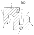
- Figure 3 shows in section a preferred arrangement of the filiform element.
- At least one heating wire 1 is coated in a plastic sheath 2 comprising two parts 3a, 3b of conjugate shape, intended to fit together by vertical translation.
- Each fitting part 3a or 3b comprises a female part 6a or 6b and a male part 7a or 7b.
- the female parts 6a, 6b each consist of a groove open upwards or downwards.
- the female part 6a of the interlocking part 3a has a cross-sectional shape analogous to the male part 7b of the other interlocking part 3b and the male part 7a of the interlocking part 3a has a cross-sectional shape similar to the female part 6b of the interlocking part 3b.
- the section of the filiform element thus has a general shape of S rotated by 90 °.
- the heating wire 1 is placed, tangent to the surface of the sheath intended to come into contact with the surface of one or more tubular element (s) to be connected. Preferably, this heating wire 1 will be placed under one of the female parts 6a or 6b.
- this filiform element may comprise at least one second heating wire 8 placed tangent to one of the contact surfaces of sections of filiform element preferably connected as shown in FIG. 3 placed tangent to the interior surface of the female part 6a or 6b, at a certain distance from the surface opposite the surface intended to come into contact with the tubular elements to be connected.
- This second heating wire 8 is used to stiffen the fitting or the insert produced. It in fact allows the mutual welding of the sections of connected filiform element.
- the filiform element can be manufactured by extruding polyethylene around the resistant wire (s).
- an electro-welding insert intended for a welding sleeve for assembling tubular plastic parts, it may be fixed according to a helical winding.
- an electro-welding insert intended for a pipe bypass connection by perforation, it may be fixed in a spiral to form a circular disc.
- the filiform element is therefore very long, and can be cut and shaped according to various shapes thanks to the slots 5 or possibly to cuts made according to specific needs.
- the repairer has at his disposal a length of profiled sheathed wire, as previously described. It can wind this sheathed wire around the pipe (s) to be treated, possibly even in several layers. It then applies the appropriate voltage to perform the electro-welding.
- the thread can in this sense be supplied with charts allowing the operator to apply the appropriate tension for the appropriate duration.
- a first type of chart makes it possible to determine the duration of welding as a function of the applied voltage and the diameter of the pipe (s).
- the sheathed wire can be provided with visual cues at precise lengths, so that the wire can be cut quickly to the desired length depending on the diameter.
- a second type of chart makes it possible to determine the duration of welding as a function of the applied voltage and the resistivity of the winding.
- the filiform element according to the previous invention therefore forms a ready-to-use product, practical and reliable, for the treatment of pipelines, the implementation of which requires only current electrical devices (ohmeter, battery, transformer, ).
Abstract
Description
- La présente invention se rapporte à un fil résistant gainé profilé, pouvant donc être relié, selon diverses formes, à un fil analogue adjacent. Ce fil est en particulier destiné à former un insert chauffant pour raccord électro-soudable, notamment de canalisation en matière plastique, telles que les canalisations de distribution de gaz réalisées en général en polyéthylène haute densité.
- La technique d'électro-soudage consiste à chauffer les surfaces de contact des pièces, grâce à un fil chauffant noyé dans la pièce de raccordement et formant une résistance électrique, afin d'atteindre la température de soudage des matériaux.
- La technique la plus couramment utilisée pour former de tels raccords, est le surmoulage par injection. Le fil chauffant est mis en place dans une bobine, laquelle est surmoulée pour former la pièce de raccordement. Ainsi le fil est relativement proche de la surface intérieure de l'élément. Pour réaliser une bonne qualité de soudage il est en effet souhaitable que le fil soit le plus près possible de cette surface intérieure de contact.
- La fabrication de ce manchon ensuite surmoulé est donc un processus important de la réalisation de raccords électro-soudables.
- En général, le fil est enroulé sur le manchon relativement fin, soit directement et fixé, par exemple, par chauffage du fil (brevet européen 0303 909 GLYMWED TUBES AND FITTINGS LIMITED), soit introduit dans une rainure hélicoïdale préformée sur le manchon (brevet européen 0262 735 WAVIN).
- Il a été également proposé de former des inserts préfabriqués, à partir d'un fil gainé.
- C'est le cas du raccord d'électro-soudure du brevet européen 0036 963 (GEORG FISHER AKTIEN GESELLSCHAFT), selon lequel un fil enrobé cylindrique est enroulé en hélice, l'enrobage de chaque fil est solidement assemblé à l'enrobage de la spire suivante, par soudage lors de la fabrication de l'enroulement, pour former une douille compacte.
- C'est également un insert de ce type qui est décrit dans le brevet français 2 503 020 (SERAP), selon lequel un fil gainé est bobiné à spires jointives sur un mandrin extensible, le fil est chauffé suffisamment pour que la gaine ramollisse et le mandrin est mis en extension par un noyau conique pour que la surface extérieure du mandrin soit pratiquement en contact avec une génératrice du fil résistant. Ainsi les spires sont soudées ensemble et on obtient un manchon destiné a être inséré dans un raccord électro-soudable.
- Selon une autre technique divulguée dans le brevet français 2 040 143 (GEBERT et Cie), le conducteur de chauffage est constitué par un ruban de matière plastique sur lequel le fil de chauffage est disposé en spires écartées les unes des autres. Ce conducteur de chauffage est ensuite introduit entre les tubes à assembler.
- Des inserts de chauffage sont également utilisés dans les pièces de raccordement, utilisées pour réaliser une dérivation grâce à une perforation in-situ d'une canalisation.
- De telles pièces de raccordement sont en général en deux parties recevant la canalisation. La perforation est réalisée après soudure par chauffage de la canalisation à l'emplacement de la zone à perforer, ce chauffage étant obtenu au moyen d'une résistance électrique de chauffage.
- De la même façon que dans le cas du manchon de raccordement, il a été cherché à réaliser un insert de chauffage préfabriqué.
- En effet, selon l'art antérieur décrit par exemple dans le brevet français 2 171 223 (ROLLMAPLAST AG), un fil résistif gainé en forme de spirale ou autre, est pris dans la masse de la partie de selle par surmoulage.
- Un insert préfabriqué est décrit, par contre dans le brevet français 2 519 578 (INNOVATION TECHNIQUE SAM) ; cet insert est formé d'une plaquette d'épaisseur relativement faible moulée et comprenant une gorge dans laquelle est mise en place le fil chauffant en forme de spirale ; cet insert est destiné à être incorporé à la face intérieure de la selle, de préférence pendant le moulage de celle-ci.
- La préfabrication de ces inserts de chauffage permet la fabrication en grande série, garantit une bonne qualité des pièces de raccordement, tout en facilitant de façon importante les processus du moulage ou de surmoulage.
- En résumé, cette préfabrication est obtenue principalement par liaison au préalable, avant la fabrication de la pièce de raccordement elle-même, du fil de chauffage à une base de matière plastique de forme adaptée ou par soudure directe de la gaine du fil avec celle du fil adjacent par chauffage sur une surface de support adéquate.
- Or, ces techniques entraînent l'élaboration de pièces d'inserts spécifiques à chaque utilisation, à savoir dans le cas de raccords cylindriques classiques, de manchons et dans le cas de raccords à perforation, de disques ou plaquettes et également à chaque diamètre des éléments tubulaires à raccorder.
- L'objet de l'invention est d'allier l'avantage de la préfabrication et celui d'un fil multifonctions pouvant être utilisé pour plusieurs applications.
- Pour ce faire, la présente invention consiste en un fil gainé dont la gaine présente des parties de fixation mécanique, pour permettre la liaison aisée, par exemple par conjugaison de forme, d'un élément de fil avec un autre élément de fil, afin de constituer un insert de forme adapté à l'utilisation que l'on lui destine.
- Ce fil gainé peut donc être fabriqué en grande longueur, tel un fil gainé cylindrique classique et peut être fixé selon une forme et des dimensions quelconques.
- Son agencement par fixation est particulièrement simple, et donc le coût de production d'inserts de ce type est relativement bas, ne nécessitant pas d'appareillage spécifique et complexe de moulage, de chauffage ou de pose.
- Conformément à l'invention, l'élément filiforme est donc constitué d'au moins un fil résistant enrobé d'une matière thermoplastique et il est remarquable en ce que l'enrobage présente des parties de fixation mécanique, dont l'une est destinée à coopérer avec l'autre partie de fixation d'un élément filiforme identique adjacent à assembler.
- De préférence les parties de fixation mécanique sont constituées de parties profilées, de forme conjuguée, situées sur des faces opposées de l'élément filiforme, et se fixant l'une à l'autre par emboîtement. Ce mode de fixation est en effet particulièrement simple à mettre en oeuvre et la fabrication de l'élément filiforme peut se faire par extrusion sans nécessité d'appareillage complexe.
- Selon un mode de réalisation, ces parties de forme conjuguée peuvent être des parties profilées, mâle sur l'une des faces de l'élément et femelle sur l'autre face, par exemple en queue d'aronde.
- Selon un autre mode de réalisation, ces parties de fixation comportent chacune une partie mâle et une partie femelle, s'emboitant mutuellement par poussée verticale ; dans ce dernier cas elles peuvent avoir une forme de rainure de section trapézoïdale et ces rainures peuvent être pourvues sur au moins une de leur face intérieure de crans de blocage.
- Ces deux modes de réalisation ne sont donnés qu'à titre d'exemple, puisque bien sûr, on peut réaliser ces parties profilées selon d'autres formes permettant l'emboîtement et l'encliquetage. Ces diverses formes permettent l'adaptation facile aux formes d'inserts à réaliser. En effet selon la forme de l'insert, il peut être plus avantageux d'avoir à réaliser l'emboîtement par simple poussée latérale, par poussée verticale ou par combinaison de ces deux déplacements.
- Afin de permettre la réalisation d'inserts nécessitant la courbure de l'élément filiforme, par exemple en spirale pour la réalisation d'un disque circulaire, l'élément filiforme peut être pourvu de fentes latérales. Des fentes plus importantes en biseau peuvent également être envisagées, pour la réalisation de pliage angulaire.
- L'élément filiforme a donc une section de forme générale rectangulaire et le fil résistant est le plus proche possible d'une de ses faces, de préférence il affleure même sur une de ses faces. En effet comme on l'a vu plus haut un fil chauffant affleurant permet la réalisation d'une soudure des surfaces en contact de meilleure qualité.
- De façon avantageuse, l'élément filiforme peut également comporter au moins un second fil chauffant disposé tangent à l'une des surfaces de contact de deux tronçons d'élément filiforme reliés. Ainsi, également par électro-soudage, on améliore la rigidification de l'élément réalisé à l'aide d'au moins un fil filiforme tel que décrit.
- Cet élément filiforme est destiné en particulier à réaliser des inserts d'électro-soudage.
- Dans le cas d'inserts destinés à des manchons pour l'assemblage de deux pièces tubulaires en matière thermoplastique, il sera de préférence assemblé en un enroulement hélicoïdal.
- Dans le cas d'inserts destinés à des raccords de dérivation avec perforation d'une pièce tubulaire en matière thermoplastique, il sera de préférence assemblé en une spirale, afin de former un disque circulaire.
- Une autre utilisation de l'élément filiforme selon la présente invention consiste à traiter par électro-soudage des canalisations, de préférence en assemblant par enroulement ledit élément filiforme sur la ou les canalisation(s) et en appliquant une tension au(x) fil(s) chauffant(s) pour réaliser la réparation ou le raccordement des canalisations. Cette application a pour principal avantage de permettre un traitement de canalisations simple, rapide et fiable, à l'aide d'un produit unique et d'appareils électriques courants.
- L'invention est exposée ci-après plus en détail à l'aide de dessins représentant seulement un mode d'exécution.
- - la figure 1 et la figure 2 représentent, en perspective, deux exemples de réalisation d'éléments filiformes conforme à l'invention.
- - la figure 3 représente en section un mode de réalisation préféré de l'élément filiforme.
- Les figures 1 et 2 représentent deux éléments filiformes, de section générale rectangulaire, formés d'un fil résistant 1 enrobé d'une gaine 2 de matière plastique, en particulier du polyéthylène. Comme on peut le voir sur leur section le fil résistant 1 a une génératrice qui affleure l'une des faces de la section que l'on appelera face inférieure.
- Les faces latérales de l'élément filiforme sont pourvues de parties de fixation mécanique 3a, 3b. Selon les exemples représentés, ces parties de fixation mécanique sont constituées de parties profilées destinées à coopérer par conjugaison de forme, par emboîtement ou encliquètement, avec les parties correspondantes d'un tronçon d'élément filiforme adjacent.
- Selon la figure 1, ces parties profilées sont constituées d'une partie femelle 3a et d'une partie mâle 3b, de forme conjuguée ; selon l'exemple représenté elles sont en forme de queue d'aronde, mais elles peuvent être également de forme semi-cylindrique ou de toute autre forme permettant un encliquetage aisé.
- Sur au moins une des faces latérales de l'élément filiforme, peuvent être prévues des fentes 5 destinées à faciliter la courbure ou le pliage de l'élément.
- Selon la figure 2 les parties profilées sont constituées identiques mais symétriques par rapport à l'axe longitudinal de l'élément filiforme, ces parties profilées 3a, 3b formant des espèces de crochet destinés à s'emboîter l'un dans l'autre. Selon l'exemple représenté ces parties de crochet sont formées par des rainures de section trapézoïdale qui présentent sur leur surface intérieure inclinée de crans 4 destinés à les bloquer en position emboîtée. La forme et la section de ces rainures peuvent évidemment être d'une autre forme, par exemple rectangulaire ou triangulaire.
- L'élément filiforme tel que décrit précédemment peut comporter au lieu d'un seul fil résistant 1 plusieurs fils en parallèle, l'élément filiforme étant alors élargi en conséquence. Mais ce nombre de fils résistants 1 est limité par la nécessité de pouvoir conformer de façon souhaitée l'élément.
- La figure 3 représente en section un agencement préféré de l'élément filiforme.
- Selon ce mode de réalisation, au moins un fil chauffant 1 est enrobé dans une gaine 2 en matière plastique comportant deux parties 3a, 3b de forme conjuguée, destinées à s'emboiter par translation verticale.
- Chaque partie d'emboitement 3a ou 3b comporte une partie femelle 6a ou 6b et une partie mâle 7a ou 7b.
- Les parties femelles 6a, 6b sont constituées chacune d'une rainure ouverte vers le haut ou vers le bas. La partie femelle 6a de la partie d'emboitement 3a a une forme en section analogue à la partie mâle 7b de l'autre partie d'emboitement 3b et la partie mâle 7a de la partie d'emboitement 3a a une forme en section analogue à la partie femelle 6b de la partie d'emboitement 3b. La section de l'élément filiforme a ainsi une forme générale de S tourné de 90°.
- Le fil chauffant 1 est placé, tangent à la surface de la gaine destinée à venir en contact avec la surface d'un ou des élément(s) tubulaire(s) à raccorder. De préférence, ce fil chauffant 1 sera placé sous l'une des parties femelles 6a ou 6b.
- Eventuellement cet élément filiforme peut comporter au moins un second fil chauffant 8 placé tangent à l'une des surfaces de contact de tronçons d'élément filiforme reliés de préférence tel que représenté sur la figure 3 placé tangent à la surface intérieure de la partie femelle 6a ou 6b, à une certaine distance de la surface opposée à la surface destinée à venir en contact avec les éléments tubulaires à raccorder.
- Ce second fil chauffant 8 sert à la rigidification du raccord ou de l'insert réalisé. Il permet en effet la soudure mutuelle des tronçons d'élément filiforme reliés.
- L'élément filiforme peut être fabriqué par extrusion de polyéthylène autour du ou des fils résistants.
- Il est notamment destiné à la réalisation d'inserts d'électro-soudure, de forme et de dimension variées.
- Dans le cas d'un insert d'électro-soudage destinés à un manchon de soudage pour l'assemblage de pièces tubulaires en matière plastique, il pourra être fixé selon un enroulement hélicoïdal.
- Dans le cas d'un insert d'électro-soudage destiné à un raccord de dérivation de canalisation par perforation, il pourra être fixé selon une spirale pour former un disque circulaire.
- L'élément filiforme se présente donc en grande longueur, et peut être découpé et conformé selon des formes diverses grâce aux fentes 5 ou éventuellement à des découpes réalisées selon les besoins spécifiques.
- Une autre application très intéressante de cet élément filiforme d'électro-soudage est le raccordement ou la réparation de canalisations in-situ.
- Le réparateur a à sa disposition une longueur de fil gainé profilé, telle que précédemment décrit. Il peut enrouler ce fil gainé autour de la ou des canalisation(s) à traiter éventuellement même en plusieurs couches. Il applique ensuite la tension adéquate pour réaliser l'électro-soudage.
- Le fil peut dans ce sens être fourni avec des abaques permettant à l'opérateur d'appliquer la tension adéquate durant la durée convenable.
- Un premier type d'abaque permet de déterminer la durée de soudure en fonction de la tension appliquée et du diamètre de la ou des canalisation(s). Dans ce cas, le fil gainé peut être pourvu de repères visuels à des longueurs précises, afin que le fil puisse être coupé rapidement à la longueur souhaitée en fonction du diamètre.
- Un second type d'abaque permet de déterminer la durée de soudure en fonction de la tension appliquée et de la résistivité de l'enroulement.
- L'élément filiforme selon la précédente invention forme donc un produit prêt à l'emploi, pratique et fiable, pour le traitement de canalisations, dont la mise en oeuvre ne nécessite que des appareils électriques courants (ohmètre, batterie, transformateur,...).
Claims (15)
Applications Claiming Priority (2)
| Application Number | Priority Date | Filing Date | Title |
|---|---|---|---|
| FR8907648A FR2648076B1 (fr) | 1989-06-09 | 1989-06-09 | Fil gaine profile destine notamment a former un insert d'electro-soudure |
| FR8907648 | 1989-06-09 |
Publications (2)
| Publication Number | Publication Date |
|---|---|
| EP0402201A2 true EP0402201A2 (fr) | 1990-12-12 |
| EP0402201A3 EP0402201A3 (fr) | 1992-03-18 |
Family
ID=9382556
Family Applications (1)
| Application Number | Title | Priority Date | Filing Date |
|---|---|---|---|
| EP19900401445 Withdrawn EP0402201A3 (fr) | 1989-06-09 | 1990-05-30 | Fil gainé profilé destiné notamment à former un insert d'électro-soudure |
Country Status (12)
| Country | Link |
|---|---|
| US (1) | US5107098A (fr) |
| EP (1) | EP0402201A3 (fr) |
| JP (1) | JPH0330931A (fr) |
| KR (1) | KR910020361A (fr) |
| CN (1) | CN1047825A (fr) |
| BR (1) | BR9002742A (fr) |
| CA (1) | CA2018555A1 (fr) |
| FR (1) | FR2648076B1 (fr) |
| MC (1) | MC2128A1 (fr) |
| MX (1) | MX173103B (fr) |
| PT (1) | PT94264A (fr) |
| TN (1) | TNSN90079A1 (fr) |
Cited By (4)
| Publication number | Priority date | Publication date | Assignee | Title |
|---|---|---|---|---|
| EP0615833A1 (fr) * | 1993-03-19 | 1994-09-21 | Vip Industries Limited | Méthode de soudage à chaud et valise |
| FR2743525A1 (fr) * | 1996-01-17 | 1997-07-18 | Toa Kokyu Tugitebarubu Seizo C | Procede pour souder ensemble des feuilles de matiere plastique et joint utilise dans ce procede |
| WO1997026459A1 (fr) * | 1996-01-18 | 1997-07-24 | Dan-Pal | Structures constituees d'unites de panneaux et de pieces de liaison, procede de fabrication desdites structures |
| ES2133039A1 (es) * | 1996-03-01 | 1999-08-16 | Toa Kokyu Tugitevarubu Seizo C | Metodo de soldadura de hojas de plastico entre si y junta usada en el mismo. |
Families Citing this family (12)
| Publication number | Priority date | Publication date | Assignee | Title |
|---|---|---|---|---|
| IN176911B (fr) * | 1993-02-05 | 1996-10-05 | V I P Ind Ltd | |
| DE4307704A1 (de) * | 1993-03-11 | 1994-09-15 | Wilhelm Hegler | Verfahren zum Verschweißen von aus thermoplastischem Kunststoff bestehenden Rohrstücken |
| US5459811A (en) * | 1994-02-07 | 1995-10-17 | Mse, Inc. | Metal spray apparatus with a U-shaped electric inlet gas heater and a one-piece electric heater surrounding a nozzle |
| CN1069080C (zh) * | 1996-01-30 | 2001-08-01 | 东亚高级连接阀制造株式会社 | 塑料片材熔接在一起的方法及其采用之接头 |
| WO1997047913A1 (fr) * | 1996-06-12 | 1997-12-18 | Manibs Spezialarmaturen Gmbh & Co. Kg | Procede de production d'un element de robinetterie pour tubes, en materiau thermosoudable |
| US5951902A (en) * | 1997-12-29 | 1999-09-14 | Kerotest Manufacturing Corp. | Method and apparatus for electrofusing thermoplastic |
| US6781099B2 (en) * | 2001-03-12 | 2004-08-24 | Karl-Heinz Krah Gmbh | Electrofusion socket forming system |
| US6531850B1 (en) * | 2001-08-20 | 2003-03-11 | Deere & Company | Load controller utilizing alternator field excitation |
| GB2422348A (en) | 2005-01-25 | 2006-07-26 | Uponor Innovation Ab | Joining metal to plastic with heat activated adhesive |
| CN102052539B (zh) * | 2010-10-28 | 2012-08-22 | 浙江大学 | 采用榫卯结构的管道电熔接头及电熔焊接方法 |
| EP3575662B1 (fr) * | 2018-05-29 | 2021-09-29 | Georg Fischer Rohrleitungssysteme AG | Bande de soudage électrique |
| CN109501148B (zh) * | 2018-12-13 | 2020-11-06 | 盐城市沿海新能源汽车科技有限公司 | 一种模具注塑用热流道加热装置 |
Citations (9)
| Publication number | Priority date | Publication date | Assignee | Title |
|---|---|---|---|---|
| FR1337887A (fr) * | 1962-08-09 | 1963-09-20 | Méthode et appareil pour la fabrication de tuyaux renforcés en matière plastique et tuyaux ainsi obtenus | |
| CH450706A (de) * | 1966-01-21 | 1968-01-31 | Keller Hans | Verfahren zur Herstellung einer zum Verschweissen von Teilen aus thermoplastischem Kunststoff dienenden Heizzwischenlage |
| US3378672A (en) * | 1966-03-18 | 1968-04-16 | Susquehanna Corp | Insulated, electrical resistance wire and welding sleeve made therefrom |
| FR2083368A1 (fr) * | 1970-03-18 | 1971-12-17 | Bosch | |
| FR2356765A1 (fr) * | 1976-06-30 | 1978-01-27 | Valmet Oy | Procede de fixation d'une bande de recouvrement dans un rouleau de recouvrement rainure ou non rainure d'une machine a papier |
| FR2461872A1 (fr) * | 1977-11-14 | 1981-02-06 | Dayco Corp | Structure de tuyau flexible et procede pour la fabriquer |
| US4376005A (en) * | 1980-09-22 | 1983-03-08 | Dayco Corporation | Method of making hose |
| FR2522457A1 (fr) * | 1982-03-01 | 1983-09-02 | Sloane Mfg Co R & G | Element formant resistance bifilaire, element chauffant obtenu a partir de ce dernier et procede de fabrication d'un tel element chauffant |
| GB2137298A (en) * | 1983-03-30 | 1984-10-03 | Fusion Plastics Ltd | Branch pipe fitting |
Family Cites Families (4)
| Publication number | Priority date | Publication date | Assignee | Title |
|---|---|---|---|---|
| CH480588A (de) * | 1968-04-05 | 1969-10-31 | Dynamit Nobel Ag | Profil aus thermoplastischem Kunststoff |
| DE2012783C3 (de) * | 1970-03-18 | 1974-05-09 | Siemens Ag, 1000 Berlin Und 8000 Muenchen | Vorrichtung zum Umformen von Werkstücken durch Unterwasser-Funkenentladung |
| JPS5949945A (ja) * | 1982-09-16 | 1984-03-22 | Sanyo Electric Co Ltd | 電熱線入りホ−スの製造方法 |
| US4894521A (en) * | 1988-11-21 | 1990-01-16 | Central Plastics Company | Electric heating element for fusing thermoplastic materials |
-
1989
- 1989-06-09 FR FR8907648A patent/FR2648076B1/fr not_active Expired - Fee Related
-
1990
- 1990-05-30 KR KR1019900007862A patent/KR910020361A/ko not_active Application Discontinuation
- 1990-05-30 EP EP19900401445 patent/EP0402201A3/fr not_active Withdrawn
- 1990-06-04 PT PT94264A patent/PT94264A/pt not_active Application Discontinuation
- 1990-06-04 US US07/532,451 patent/US5107098A/en not_active Expired - Fee Related
- 1990-06-05 MC MC902129A patent/MC2128A1/fr unknown
- 1990-06-06 CN CN90104237A patent/CN1047825A/zh active Pending
- 1990-06-07 JP JP2149737A patent/JPH0330931A/ja active Pending
- 1990-06-08 MX MX021083A patent/MX173103B/es unknown
- 1990-06-08 CA CA002018555A patent/CA2018555A1/fr not_active Abandoned
- 1990-06-11 TN TNTNSN90079A patent/TNSN90079A1/fr unknown
- 1990-06-11 BR BR909002742A patent/BR9002742A/pt not_active Application Discontinuation
Patent Citations (9)
| Publication number | Priority date | Publication date | Assignee | Title |
|---|---|---|---|---|
| FR1337887A (fr) * | 1962-08-09 | 1963-09-20 | Méthode et appareil pour la fabrication de tuyaux renforcés en matière plastique et tuyaux ainsi obtenus | |
| CH450706A (de) * | 1966-01-21 | 1968-01-31 | Keller Hans | Verfahren zur Herstellung einer zum Verschweissen von Teilen aus thermoplastischem Kunststoff dienenden Heizzwischenlage |
| US3378672A (en) * | 1966-03-18 | 1968-04-16 | Susquehanna Corp | Insulated, electrical resistance wire and welding sleeve made therefrom |
| FR2083368A1 (fr) * | 1970-03-18 | 1971-12-17 | Bosch | |
| FR2356765A1 (fr) * | 1976-06-30 | 1978-01-27 | Valmet Oy | Procede de fixation d'une bande de recouvrement dans un rouleau de recouvrement rainure ou non rainure d'une machine a papier |
| FR2461872A1 (fr) * | 1977-11-14 | 1981-02-06 | Dayco Corp | Structure de tuyau flexible et procede pour la fabriquer |
| US4376005A (en) * | 1980-09-22 | 1983-03-08 | Dayco Corporation | Method of making hose |
| FR2522457A1 (fr) * | 1982-03-01 | 1983-09-02 | Sloane Mfg Co R & G | Element formant resistance bifilaire, element chauffant obtenu a partir de ce dernier et procede de fabrication d'un tel element chauffant |
| GB2137298A (en) * | 1983-03-30 | 1984-10-03 | Fusion Plastics Ltd | Branch pipe fitting |
Non-Patent Citations (1)
| Title |
|---|
| PATENT ABSTRACTS OF JAPAN, vol. 8, no. 154 (M-310)[1591], 18 juillet 1984; & JP-A-59 49 945 (SANYO DENKI) 22-03-1984 * |
Cited By (4)
| Publication number | Priority date | Publication date | Assignee | Title |
|---|---|---|---|---|
| EP0615833A1 (fr) * | 1993-03-19 | 1994-09-21 | Vip Industries Limited | Méthode de soudage à chaud et valise |
| FR2743525A1 (fr) * | 1996-01-17 | 1997-07-18 | Toa Kokyu Tugitebarubu Seizo C | Procede pour souder ensemble des feuilles de matiere plastique et joint utilise dans ce procede |
| WO1997026459A1 (fr) * | 1996-01-18 | 1997-07-24 | Dan-Pal | Structures constituees d'unites de panneaux et de pieces de liaison, procede de fabrication desdites structures |
| ES2133039A1 (es) * | 1996-03-01 | 1999-08-16 | Toa Kokyu Tugitevarubu Seizo C | Metodo de soldadura de hojas de plastico entre si y junta usada en el mismo. |
Also Published As
| Publication number | Publication date |
|---|---|
| KR910020361A (ko) | 1991-12-20 |
| JPH0330931A (ja) | 1991-02-08 |
| FR2648076B1 (fr) | 1991-11-15 |
| MX173103B (es) | 1994-02-01 |
| TNSN90079A1 (fr) | 1991-03-05 |
| CN1047825A (zh) | 1990-12-19 |
| EP0402201A3 (fr) | 1992-03-18 |
| CA2018555A1 (fr) | 1990-12-09 |
| FR2648076A1 (fr) | 1990-12-14 |
| BR9002742A (pt) | 1991-08-20 |
| MC2128A1 (fr) | 1992-01-03 |
| PT94264A (pt) | 1992-01-31 |
| US5107098A (en) | 1992-04-21 |
Similar Documents
| Publication | Publication Date | Title |
|---|---|---|
| EP0402201A2 (fr) | Fil gainé profilé destiné notamment à former un insert d'électro-soudure | |
| EP0069020B1 (fr) | Dispositif en matière plastique pour réaliser une perforation dans un élément sous-jacent en matière plastqiue, procédé de fabrication d'un tel dispositif et sa mise en oeuvre pour réaliser des dérivations de canalisations | |
| FR2522457A1 (fr) | Element formant resistance bifilaire, element chauffant obtenu a partir de ce dernier et procede de fabrication d'un tel element chauffant | |
| JP2687994B2 (ja) | フィッティング及びフィッティングを用いる管継ぎ目 | |
| FR2743402A1 (fr) | Manchon de gaine tressee destine a etre enfile sur au moins un element allonge a proteger, et procede de fabrication d'un tel manchon | |
| EP0253721B1 (fr) | Manchon thermorétractable comportant des moyens pour contrôler son chauffage uniforme, et procédé de fabrication de ce manchon | |
| WO1998047210A1 (fr) | Piece de raccordement etanche d'un tube a l'orifice d'une paroi | |
| JP2770643B2 (ja) | ポリオレフィンパイプを結合する方法及びカプラ | |
| EP0615091B1 (fr) | Raccord thermosoudable pour tube sur un matériau plastique ainsi qu'un procédé pour le fabriquer | |
| FR2484162A1 (fr) | Dispositif de raccordement etanche d'un cable coaxial sous-marin a un repeteur, procede de fabrication de ce dispositif et moule utilisable dans ce procede | |
| FR2516439A1 (fr) | Procede de soudage electrique de pieces en matiere plastique, en particulier pour canalisations de fluides et manchons de raccordement pour de telles canalisations | |
| FR2580437A1 (fr) | Procede de fabrication d'un element tubulaire monobloc pour la protection de plusieurs cables et element fabrique selon ce procede | |
| FR2477062A1 (fr) | Procede de fabrication d'un tube flexible a plusieurs couches enroulees helicoidalement et le tube ainsi obtenu | |
| FR2748415A1 (fr) | Element de raccord pour un assemblage de pieces en materiaux thermoplastiques par soudage et procede de fabrication d'un tel element | |
| FI105415B (sv) | Ändpreparering av ett termoplaströr framställt genom spirallindning av en hålprofil | |
| FR2615332A1 (fr) | Tube profile en matiere plastique | |
| FR2627026A1 (fr) | Procede pour realiser l'etancheite entre un cable ou element analogue et une conduite externe recevant ce cable et bande composite pour la mise en oeuvre de ce procede | |
| EP0105068B1 (fr) | Raccord électrosoudable en matière thermoplastique et procédé de fabrication | |
| FR2735511A1 (fr) | Gaine de cable a structure multi-couche, son procede de fabrication et machine pour mettre en oeuvre ce procede | |
| JPH08224784A (ja) | 熱可塑性樹脂製品の溶融着用発熱体 | |
| EP0586283B1 (fr) | Pièce de raccordement électrosoudable à bornes de connexion perfectionnées et son procédé de fabrication | |
| FR2535570A1 (fr) | Bande a chauffage electrique pour la realisation d'une jonction par manchon pour canalisation tubulaire thermiquement isolee, et son procede de fabrication | |
| BE875898R (fr) | Joint pour tuyaux thermoplastiques a parois multiples et procede pour sa production | |
| JP2521645B2 (ja) | 被溶融着熱可塑性樹脂体 | |
| EP0340123A1 (fr) | Elément tubulaire isolé pour la réalisation d'installations aériennes véhiculant des fluides, procédé pour sa réalisation et installations constituées de tels éléments |
Legal Events
| Date | Code | Title | Description |
|---|---|---|---|
| PUAI | Public reference made under article 153(3) epc to a published international application that has entered the european phase |
Free format text: ORIGINAL CODE: 0009012 |
|
| AK | Designated contracting states |
Kind code of ref document: A2 Designated state(s): AT BE CH DE DK ES FR GB GR IT LI LU NL SE |
|
| PUAL | Search report despatched |
Free format text: ORIGINAL CODE: 0009013 |
|
| AK | Designated contracting states |
Kind code of ref document: A3 Designated state(s): AT BE CH DE DK ES FR GB GR IT LI LU NL SE |
|
| 17P | Request for examination filed |
Effective date: 19921106 |
|
| 17Q | First examination report despatched |
Effective date: 19940426 |
|
| STAA | Information on the status of an ep patent application or granted ep patent |
Free format text: STATUS: THE APPLICATION IS DEEMED TO BE WITHDRAWN |
|
| 18D | Application deemed to be withdrawn |
Effective date: 19940907 |