EP0401854B1 - Einrichtung zur orthogonalen Transformationskodierung - Google Patents
Einrichtung zur orthogonalen Transformationskodierung Download PDFInfo
- Publication number
- EP0401854B1 EP0401854B1 EP19900110889 EP90110889A EP0401854B1 EP 0401854 B1 EP0401854 B1 EP 0401854B1 EP 19900110889 EP19900110889 EP 19900110889 EP 90110889 A EP90110889 A EP 90110889A EP 0401854 B1 EP0401854 B1 EP 0401854B1
- Authority
- EP
- European Patent Office
- Prior art keywords
- orthogonal transform
- signals
- data amount
- coding device
- transform coding
- Prior art date
- Legal status (The legal status is an assumption and is not a legal conclusion. Google has not performed a legal analysis and makes no representation as to the accuracy of the status listed.)
- Expired - Lifetime
Links
Images


Classifications
-
- H—ELECTRICITY
- H04—ELECTRIC COMMUNICATION TECHNIQUE
- H04N—PICTORIAL COMMUNICATION, e.g. TELEVISION
- H04N5/00—Details of television systems
- H04N5/76—Television signal recording
- H04N5/91—Television signal processing therefor
- H04N5/92—Transformation of the television signal for recording, e.g. modulation, frequency changing; Inverse transformation for playback
- H04N5/926—Transformation of the television signal for recording, e.g. modulation, frequency changing; Inverse transformation for playback by pulse code modulation
- H04N5/9261—Transformation of the television signal for recording, e.g. modulation, frequency changing; Inverse transformation for playback by pulse code modulation involving data reduction
- H04N5/9264—Transformation of the television signal for recording, e.g. modulation, frequency changing; Inverse transformation for playback by pulse code modulation involving data reduction using transform coding
-
- H—ELECTRICITY
- H04—ELECTRIC COMMUNICATION TECHNIQUE
- H04N—PICTORIAL COMMUNICATION, e.g. TELEVISION
- H04N19/00—Methods or arrangements for coding, decoding, compressing or decompressing digital video signals
- H04N19/10—Methods or arrangements for coding, decoding, compressing or decompressing digital video signals using adaptive coding
- H04N19/102—Methods or arrangements for coding, decoding, compressing or decompressing digital video signals using adaptive coding characterised by the element, parameter or selection affected or controlled by the adaptive coding
- H04N19/124—Quantisation
-
- H—ELECTRICITY
- H04—ELECTRIC COMMUNICATION TECHNIQUE
- H04N—PICTORIAL COMMUNICATION, e.g. TELEVISION
- H04N19/00—Methods or arrangements for coding, decoding, compressing or decompressing digital video signals
- H04N19/10—Methods or arrangements for coding, decoding, compressing or decompressing digital video signals using adaptive coding
- H04N19/102—Methods or arrangements for coding, decoding, compressing or decompressing digital video signals using adaptive coding characterised by the element, parameter or selection affected or controlled by the adaptive coding
- H04N19/132—Sampling, masking or truncation of coding units, e.g. adaptive resampling, frame skipping, frame interpolation or high-frequency transform coefficient masking
-
- H—ELECTRICITY
- H04—ELECTRIC COMMUNICATION TECHNIQUE
- H04N—PICTORIAL COMMUNICATION, e.g. TELEVISION
- H04N19/00—Methods or arrangements for coding, decoding, compressing or decompressing digital video signals
- H04N19/10—Methods or arrangements for coding, decoding, compressing or decompressing digital video signals using adaptive coding
- H04N19/134—Methods or arrangements for coding, decoding, compressing or decompressing digital video signals using adaptive coding characterised by the element, parameter or criterion affecting or controlling the adaptive coding
- H04N19/146—Data rate or code amount at the encoder output
- H04N19/149—Data rate or code amount at the encoder output by estimating the code amount by means of a model, e.g. mathematical model or statistical model
-
- H—ELECTRICITY
- H04—ELECTRIC COMMUNICATION TECHNIQUE
- H04N—PICTORIAL COMMUNICATION, e.g. TELEVISION
- H04N19/00—Methods or arrangements for coding, decoding, compressing or decompressing digital video signals
- H04N19/10—Methods or arrangements for coding, decoding, compressing or decompressing digital video signals using adaptive coding
- H04N19/169—Methods or arrangements for coding, decoding, compressing or decompressing digital video signals using adaptive coding characterised by the coding unit, i.e. the structural portion or semantic portion of the video signal being the object or the subject of the adaptive coding
- H04N19/17—Methods or arrangements for coding, decoding, compressing or decompressing digital video signals using adaptive coding characterised by the coding unit, i.e. the structural portion or semantic portion of the video signal being the object or the subject of the adaptive coding the unit being an image region, e.g. an object
- H04N19/176—Methods or arrangements for coding, decoding, compressing or decompressing digital video signals using adaptive coding characterised by the coding unit, i.e. the structural portion or semantic portion of the video signal being the object or the subject of the adaptive coding the unit being an image region, e.g. an object the region being a block, e.g. a macroblock
-
- H—ELECTRICITY
- H04—ELECTRIC COMMUNICATION TECHNIQUE
- H04N—PICTORIAL COMMUNICATION, e.g. TELEVISION
- H04N19/00—Methods or arrangements for coding, decoding, compressing or decompressing digital video signals
- H04N19/10—Methods or arrangements for coding, decoding, compressing or decompressing digital video signals using adaptive coding
- H04N19/169—Methods or arrangements for coding, decoding, compressing or decompressing digital video signals using adaptive coding characterised by the coding unit, i.e. the structural portion or semantic portion of the video signal being the object or the subject of the adaptive coding
- H04N19/18—Methods or arrangements for coding, decoding, compressing or decompressing digital video signals using adaptive coding characterised by the coding unit, i.e. the structural portion or semantic portion of the video signal being the object or the subject of the adaptive coding the unit being a set of transform coefficients
-
- H—ELECTRICITY
- H04—ELECTRIC COMMUNICATION TECHNIQUE
- H04N—PICTORIAL COMMUNICATION, e.g. TELEVISION
- H04N19/00—Methods or arrangements for coding, decoding, compressing or decompressing digital video signals
- H04N19/10—Methods or arrangements for coding, decoding, compressing or decompressing digital video signals using adaptive coding
- H04N19/189—Methods or arrangements for coding, decoding, compressing or decompressing digital video signals using adaptive coding characterised by the adaptation method, adaptation tool or adaptation type used for the adaptive coding
- H04N19/192—Methods or arrangements for coding, decoding, compressing or decompressing digital video signals using adaptive coding characterised by the adaptation method, adaptation tool or adaptation type used for the adaptive coding the adaptation method, adaptation tool or adaptation type being iterative or recursive
-
- H—ELECTRICITY
- H04—ELECTRIC COMMUNICATION TECHNIQUE
- H04N—PICTORIAL COMMUNICATION, e.g. TELEVISION
- H04N19/00—Methods or arrangements for coding, decoding, compressing or decompressing digital video signals
- H04N19/50—Methods or arrangements for coding, decoding, compressing or decompressing digital video signals using predictive coding
- H04N19/503—Methods or arrangements for coding, decoding, compressing or decompressing digital video signals using predictive coding involving temporal prediction
- H04N19/51—Motion estimation or motion compensation
- H04N19/527—Global motion vector estimation
-
- H—ELECTRICITY
- H04—ELECTRIC COMMUNICATION TECHNIQUE
- H04N—PICTORIAL COMMUNICATION, e.g. TELEVISION
- H04N19/00—Methods or arrangements for coding, decoding, compressing or decompressing digital video signals
- H04N19/50—Methods or arrangements for coding, decoding, compressing or decompressing digital video signals using predictive coding
- H04N19/59—Methods or arrangements for coding, decoding, compressing or decompressing digital video signals using predictive coding involving spatial sub-sampling or interpolation, e.g. alteration of picture size or resolution
-
- H—ELECTRICITY
- H04—ELECTRIC COMMUNICATION TECHNIQUE
- H04N—PICTORIAL COMMUNICATION, e.g. TELEVISION
- H04N19/00—Methods or arrangements for coding, decoding, compressing or decompressing digital video signals
- H04N19/60—Methods or arrangements for coding, decoding, compressing or decompressing digital video signals using transform coding
-
- H—ELECTRICITY
- H04—ELECTRIC COMMUNICATION TECHNIQUE
- H04N—PICTORIAL COMMUNICATION, e.g. TELEVISION
- H04N19/00—Methods or arrangements for coding, decoding, compressing or decompressing digital video signals
- H04N19/80—Details of filtering operations specially adapted for video compression, e.g. for pixel interpolation
-
- H—ELECTRICITY
- H04—ELECTRIC COMMUNICATION TECHNIQUE
- H04N—PICTORIAL COMMUNICATION, e.g. TELEVISION
- H04N19/00—Methods or arrangements for coding, decoding, compressing or decompressing digital video signals
- H04N19/85—Methods or arrangements for coding, decoding, compressing or decompressing digital video signals using pre-processing or post-processing specially adapted for video compression
- H04N19/86—Methods or arrangements for coding, decoding, compressing or decompressing digital video signals using pre-processing or post-processing specially adapted for video compression involving reduction of coding artifacts, e.g. of blockiness
-
- H—ELECTRICITY
- H04—ELECTRIC COMMUNICATION TECHNIQUE
- H04N—PICTORIAL COMMUNICATION, e.g. TELEVISION
- H04N19/00—Methods or arrangements for coding, decoding, compressing or decompressing digital video signals
- H04N19/85—Methods or arrangements for coding, decoding, compressing or decompressing digital video signals using pre-processing or post-processing specially adapted for video compression
- H04N19/88—Methods or arrangements for coding, decoding, compressing or decompressing digital video signals using pre-processing or post-processing specially adapted for video compression involving rearrangement of data among different coding units, e.g. shuffling, interleaving, scrambling or permutation of pixel data or permutation of transform coefficient data among different blocks
-
- H—ELECTRICITY
- H04—ELECTRIC COMMUNICATION TECHNIQUE
- H04N—PICTORIAL COMMUNICATION, e.g. TELEVISION
- H04N19/00—Methods or arrangements for coding, decoding, compressing or decompressing digital video signals
- H04N19/10—Methods or arrangements for coding, decoding, compressing or decompressing digital video signals using adaptive coding
- H04N19/102—Methods or arrangements for coding, decoding, compressing or decompressing digital video signals using adaptive coding characterised by the element, parameter or selection affected or controlled by the adaptive coding
- H04N19/13—Adaptive entropy coding, e.g. adaptive variable length coding [AVLC] or context adaptive binary arithmetic coding [CABAC]
-
- H—ELECTRICITY
- H04—ELECTRIC COMMUNICATION TECHNIQUE
- H04N—PICTORIAL COMMUNICATION, e.g. TELEVISION
- H04N19/00—Methods or arrangements for coding, decoding, compressing or decompressing digital video signals
- H04N19/10—Methods or arrangements for coding, decoding, compressing or decompressing digital video signals using adaptive coding
- H04N19/134—Methods or arrangements for coding, decoding, compressing or decompressing digital video signals using adaptive coding characterised by the element, parameter or criterion affecting or controlling the adaptive coding
- H04N19/146—Data rate or code amount at the encoder output
-
- H—ELECTRICITY
- H04—ELECTRIC COMMUNICATION TECHNIQUE
- H04N—PICTORIAL COMMUNICATION, e.g. TELEVISION
- H04N19/00—Methods or arrangements for coding, decoding, compressing or decompressing digital video signals
- H04N19/30—Methods or arrangements for coding, decoding, compressing or decompressing digital video signals using hierarchical techniques, e.g. scalability
-
- H—ELECTRICITY
- H04—ELECTRIC COMMUNICATION TECHNIQUE
- H04N—PICTORIAL COMMUNICATION, e.g. TELEVISION
- H04N19/00—Methods or arrangements for coding, decoding, compressing or decompressing digital video signals
- H04N19/90—Methods or arrangements for coding, decoding, compressing or decompressing digital video signals using coding techniques not provided for in groups H04N19/10-H04N19/85, e.g. fractals
- H04N19/91—Entropy coding, e.g. variable length coding [VLC] or arithmetic coding
Definitions
- the present invention relates to an apparatus for orthogonal transform coding for use in suppressing code signal quantity to be processed and transmitted.
- High efficiency coding has been important with development of digital technology of picture signals.
- orthogonal transform coding in which input time sequential signals are transformed to different signals of an orthogonal function such as frequency component.
- orthogonal transformation a Fourier transformation, a discrete cosine transformation (DCT) and an Hadamard transformation are well known.
- DCT discrete cosine transformation
- DCT has been noticed as the orthogonal transform suitable for processing the picture information.
- EP-A-0 267 579 defining the closest prior art from which the invention proceeds discloses an image coding system having a plurality of coding characteristics such as quantization characteristics.
- a coding control circuit selects either one of the coding characteristics by forming a histogram in response to a sequence of coefficients resulting from a sequence of digital image signals, to monitor an amount of information in every one of predetermined intervals. The amount of information is calculated by summing up the coefficients in relation to every one of the coding characteristics. An optimum one of the coding characteristics is indicated by the coding control circuit to code the coefficient sequence into a sequence of coded signals in accordance with the optimum coding characteristics.
- the coefficient sequence in each frame may be divided into a sequence of blocks each of which is judged to be either valid or invalid in relation to each coding characteristic. Results of judgement may be included in the amount of information.
- EP-A-0 207 774 discloses a block encoder comprising first block generating means for constituting a three-dimensional large size block, and a plurality of second block generating means for dividing the large size block into small size blocks.
- the small size blocks of two dimensions and three dimensions are changed over adaptively in dependence on image information.
- FIG. 1 shows an example of a conventional high efficiency coding device in which 1 denotes an input unit, 2 a blocking unit, 3 a DCT unit, 4 an adaptive quantizer, 5 a variable length encoder, 6 a data buffer and 7 an output unit.
- the digital image signals input from the input unit 1 are separated into blocks for DCT unit basis in the blocking unit 2.
- two dimensional DCT for a block constructed by total 64 picture elements made of the horizontal 8 X vertical 8 samples is often used.
- the blocked image signals are transformed by two dimensional DCT in the DCT unit 3 and DCT components of the image signals can be obtained.
- the DCT components are quantized in the adaptive quantizer 4 and subsequently encoded with the variable length code in the variable length encoder 5, further the code rate of the encoded image signals are adjusted in a predetermined rate in the data buffer 6 and are output from the output unit 7.
- variable length encoding is a way of coding in which a word of higher generation probability is assigned by a shorter code and a word of lower generation probability is assigned by a longer code.
- Table 1 shows correspondence between the three bit data 0, 1, 27-87 and their variable length codes. In the examples, numbers 0 and 1 are assigned by 2 bit code, 2 and 3 by 3 bit code and 4, 5, 6 and 7 are assigned by 4 bit code. Table 1 data variable length code 0 00 1 01 2 100 3 101 4 1100 5 1101 6 1110 7 1111
- the generation probability of 0 and 1 is much greater than that of 4, 5, 6 and 7, the average bit number of data after the coding is smaller than 3 bits. It is noted that when the variable length coding is used, the data rate after the coding may change depending on the picture quality. Due to the fact mentioned above, in the conventional device shown in Fig. 1, in order to prevent an over flow or under flow in the data buffer 6, the adaptive quantizer 4 controls to increase the quantization width when the amount of the data in the data buffer 6 increases and to decrease the quantization width when the data amount in the data buffer 6 is decreased.
- the conventional DCT coding device as mentioned above shows drawbacks as mentioned hereinafter.
- An essential object of the present invention is to provide an orthogonal transform coding device which can transform the signals with undesired effect due to the transmission errors occurring in the variable length coding system decreased and can improve the picture quality in the high efficiency coding device.
- an orthogonal transform coding device comprising a large block forming means for assembling sample values of input signals to form a large block of the sampled input signals, a small block forming means for forming small blocks by dividing sample values of input signals into neighboring sample values, an orthogonal transform means for orthogonally transforming the sample values in the small block for each small block in a large block, when the small blocks collected in a predetermined number are called the large block, a of quantizing means having a plurality of kinds of quantizers each of which quantizes the orthogonally transformed components provided by said orthogonal transform means, a data amount estimating means for estimating data amount, a selection means for selecting an optimum quantizer in the quantizing means for every small block corresponding to the result of the estimation of the data amount of every small block by the data amount estimating means, coding means for converting the quantized value obtained in the quantizing means into variable length coded data, and transmission means for transmitting variable length code
- the coded data amount is previously estimated so that the optimum quantizer can be selectively employed for quantizing the orthogonally transformed data in the large block.
- the variable length coding can be accomplished so that predetermined length of code can be realized in a small range, whereby it is possible to use the variable length coding in such devices as digital VTRs that the transmission errors often occur.
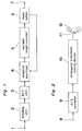
- FIG. 2 showing a general structure of an example of a digital video tape recorder (referred to as VTR hereinafter) to which an orthogonal transform coding device according to the present invention is employed.
- VTR digital video tape recorder
- reference numeral 8 denotes an input terminal of the device
- 9 an analog digital converter (A/D converter)
- 10 an orthogonal transform coding device according to the present invention
- 11 a magnetic recording head of the digital VTR
- 12 a magnetic recording tape.
- Television signals in an analog form fed from the input terminal 8 are converted into sample values of digital picture signals in the A/D converter 9.
- the sample values of the digital picture signals are subjected to data compression in the orthogonal transform coding in the orthogonal transform coding device 10, whereby the compressed data are recorded in the magnetic tape 12 through the magnetic recording head 11.
- a picture recording device or picture transmission device such as a digital VTR enables to decrease the data rate and long time recording.
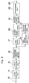
- FIG. 3 showing a block diagram of the orthogonal transform coding device according to the present invention
- 13 denotes an input terminal of the device, 14 a large blocking unit, 15 a small blocking unit, 16 an orthogonal transform coding device, 17 a data buffer, 18 a data amount estimating unit, 19 a quantizer selecting unit, 20 a plurality of quntizers, 21 a variable length encoder, 22 a transmission unit and 23 an output terminal.
- the picture signals in digital form fed from the input terminal 13 are divided into a plurality of large blocks each of which comprises a plurality of sample values in the large blocking unit 14.
- Each of the large blocks is further divided into a plurality of small blocks in the small blocking unit 15.
- Each of small block comprises sampled value of the picture data for depicting a rectangular shape on a picture plane of a display unit of a VTR.
- the sample values divided into the small block are orthogonally transformed in the orthogonal transform coding device 16.
- the orthogonal components orthogonally transformed from the sample values are inputted to the buffer 17 and data amount estimating unit 18 by the large block basis.
- the data amount of coded orthogonal components in every small block is calculated for a plurality of quantizers previously prepared, then one of the quantizers is selected for every small block in the quantizer selecting unit 19 based on the result of the calculation.
- the orthogonal components inputted to the buffer 17 are delayed therein until the quantizer is selected.
- the orthogonal components are quantized in the selected quntizers 20 and the quantized orthogonal components are coded with the variable length form in the variable length encoder 21.
- the quantized value coded with the variable length form is fed to the output terminal 23 through the transmission unit 22.
- the present invention by simulating the data amount before quantization, it becomes possible to select the optimum quantizer. Also since it is possible to control the data amount accurately different from the feed back control used in the prior art, it becomes possible to encode the data in the variable length form of a constant length of a small range, whereby the variable length coding can be employed in the digital VTR in which transmission errors occur frequently.
- the large blocking unit is explained first with reference to Fig. 4 showing detailed structure of the large blocking unit.
- 24 denotes an input terminal, 25 a memory, 26 an address controller, 27 an output terminal.
- the sample value inputted from the input terminal is inputted to the memory 25 and outputted to the output terminal 27 according to the control of the address controller 26.
- the input signals are stored in the memory 25 and outputted every large block.
- the large blocking unit is so constructed the address controller 26 shown in Fig. 4 forms every large block with every one field data of the television signals, whereby it becomes possible to form the memory 25 by a small memory in the field.
- the address controller 26 shown in Fig. 4 forms every large block with every one field data of the television signals, whereby it becomes possible to form the memory 25 by a small memory in the field.
- Fig. 5 shows the second example of the large blocking unit 14 in which 28 denotes an input terminal, 29 a frame memory, 30 an address controller, 31 an output terminal.
- every large block is formed by signals of a plurality of fields of the television signals, whereby it becomes possible to compress the data using the redundancy between the fields, a higher compression rate can be realized.
- Fig. 6 shows the third example of the large blocking unit 14 in which every large block is formed by signals of adjacent picture elements on the picture plane. Since the small blocks in the large block are adjacent each other, it becomes possible to compress the data using the redundancy between the small blocks.
- Such large blocking as shown in Fig. 6 can be realized by controlling the output address of the address controller 28 in the circuit shown in Fig. 4.
- Fig. 7 is a schematic drawing for explaining the fourth example of the large blocking unit 14, in which the shaded blocks show small blocks.
- An assembly of the shaded small blocks forms a large block.
- the large block is formed by assembling small blocks situated on various positions on the picture plane in a shuffling manner, whereby the amount of information contained in the respective large blocks is substantially equal since the amount of information on the picture plane is scattered. Accordingly, it is possible to compress the data in high efficiency, even if the amount of information is greatly position by position on the picture plane. Moreover, since the data rate of the words of the compressed codes is averaged, it is easy to control the data amount constant in the large block basis. Such blocking can be made by controlling the output address in the address controller 26 in the circuit shown in Fig. 4.
- Fig. 8 shows the fifth example of the large blocking unit 14 in which 32 denotes a brightness signal input terminal, 33 a first color difference signal input terminal, 34 a second color difference signal input terminal, 35 a frame memory, 36 an address code controller, and 37 an output terminal.
- the respective samples of the input signals of the brightness signal, the first color difference signal and second color difference signal fed from the input terminals 32, 33 and 34 are inputted to the frame memory 35 and outputted to the output terminal 37 according to the control of the address controller 36.
- each of the large block is formed by the brightness signals, the first color difference signals and second color difference signals containing them substantially the same rate. In general, the amount of information of the brightness signals and the color difference signals is unbalanced.
- each large block includes the same rate of the brightness signals and the first and second color difference signals, it becomes possible to average the amount of information similar to the fourth example of the ;large blocking unit.
- the input signals are R, G and B signals
- to cause all of the large blocks to include the same rate of R, G and B signals enables to average the amount of information.
- the small blocking unit is a unit for dividing the sample values of each of the large blocks into blocks for orthogonal transforming.
- the circuit for the small blocking is substantially the same as the circuit for the large blocking as shown in Fig. 4 which comprises a memory and address controller.
- the small blocking unit can be formed with a relatively decreased capacity of memory compared to that in the large blocking unit.
- the large blocking unit and the small blocking unit may be constructed by one memory and one address controller to decrease the circuit scale. Similar to the large blocking unit, the small blocking unit may be formed by various shapes. The examples of the small blocking are mentioned hereinafter.
- the small block is formed by the signals only in the field, whereby since the small blocks and the large blocks can be formed by the small memory in the field the circuit scale can be made small.
- the moving picture of high motion it is possible to decrease distortion by the in-field processing.
- the small block is formed by the signals of a plurality of consecutive fields, whereby it is possible to compress the data for eliminating the redundancy between the fields. Especially the above advantage can be obtained in the picture of small motion.
- Both of the first and second examples can be realized by control of the address controller of the device shown in Fig 4.
- Fig. 9 is a schematic diagram showing the third example of the small blocking unit, in which 38 denotes an input terminal, 39 a memory, 40 an address controller, 41 a motion detecting unit and 42 an output terminal.
- the signals inputted through the input terminal 38 are stored in the memory 39.
- the address controller 40 operates in response to the signal of the motion detecting unit 41 to form the small block either by the signals within one field when the motion is large or by the signals of consecutive two fields or more than two fields when the motion of picture is small, the formed small blocks are outputted from the output terminal 42, whereby it is possible to compress the data with small distortion regardless the moving picture and still picture.
- orthogonal transform coding unit 16 is explained.
- orthogonal transform is made by DCT using a small block consisting of 64 picture elements of horizontal 8 picture elements x vertical 8 picture elements is explained.
- 43 denotes an input terminal of the sample value of the small block
- 44 a horizontal DCT unit for discrete transforming in the horizontal direction
- 45 a data arranging unit for arranging horizontally lined data into vertically lined data
- 46 a vertical DCT unit
- 47 an output terminal.
- the sample values obtained in the small blocking unit 15 are inputted to the input terminal 43, discretely transformed in the horizontal direction in the horizontal DCT unit 44.
- the orthogonal components which are transformed in the DCT unit are arranged in the vertical direction in the data arranging unit 45.
- the arranged orthogonal components are discrete transformed in the vertical direction and outputted from the output terminal 47.
- Both of the horizontal and vertical orthogonal components of every small block which have been subjected to the DCT transforming in the horizontal direction and vertical direction are inputted to the buffer 17 and the data estimating unit 18 shown in Fig. 3 in the order of the orthogonal components representing the low frequency range.
- Fig. 12 48 denotes an input terminal, 49 a field buffer, 50 a first field DCT unit, 51 a second field DCT unit, 52 an adder, 53 a subtracter. 54a and 54b are output terminals.
- the signals inputted from the input terminal 48 are processed in two dimension DCT transformation in the first field DCT unit 50 and are also inputted simultaneously to the field buffer 49 in which the signals are delayed by one field.
- the signals delayed by one field are processed two dimensional DCT transformation in the second field DCT unit 51.
- the output signals of the first field DCT unit 50 and second field DCT unit 51 are added in the adder 52 and are subtracted in the subtracter 53 and the result of both calculations are outputted from the output terminals 54a and 54b.
- Fig. 12 denotes an input terminal, 49 a field buffer, 50 a first field DCT unit, 51 a second field DCT unit, 52 an adder, 53 a subtracter.
- 54a and 54b are output terminals.
- the DCT transformed components situated at the same spatial position on the picture plane but in two different fields are added on one hand and subtracted on the other hand.
- the added components are processed to quantization in the quantizer of small quantiztion range and the subtracted components are processed to quantization in the quantizer of large quantization range, whereby it is possible to compress the data amount, suppressing picture distortion.
- To calculate the sum and difference of the data is a lowest dimension (2 dimension) orthogonal transformation, it is possible to perform higher DCT by using information of more fields.
- the field buffer there may be commonly used the memory for the large blocking unit.
- the transmission unit is explained below in detail.
- Fig. 13 shows example of the quantized values of the 2 dimension DCT transformed values.
- the transmission unit 22 is adapted to transmit the portion in Fig. 13 surrounded by the smallest rectangular (the portion surrounded by the solid lines in Fig. 13) containing all of only the non zero quntized data making the lowest frequency component (the quantized values at the position of horizontal 0 and vertical 0) in the horizontal direction and vertical direction as an origin. It is noted that the data on the origin are always transmitted. Accordingly, the transmission range of the block (the rectangular shape in Fig. 13) is decided by the position of the matrix shown in Fig. 13 on which non zero highest frequency components in the horizontal direction and the vertical direction exist.
- the number of the quantized values to be transmitted is decided by the area of the transmission range, therefore the number of the quantized values can be calculated by the product of the position of the highest frequency in the horizontal direction and the highest frequency in the vertical direction.
- the information of the transmission range can be represented by the horizontal coordinate 3 bits and the vertical coordinate 3 bits, total 6 bits. Accordingly, the data amount after the coding of each small block is the sum of the variable length coded word contained in the transmission range and the information of the transmission range.
- Fig. 14 denotes an input terminal, 56 a horizontal direction high range detecting unit, 57 a vertical direction high range detecting unit, 58 a buffer, 59 a transmission range detecting unit, and 60 a gate.
- 61a and 61b are output terminals.
- the quantized values inputted from the input terminal 55 are applied to the horizontal direction high range detecting unit 56 and the vertical direction high range detecting unit 57.
- the horizontal direction high range detecting unit 56 there is detected a position on which the highest frequency component of non zero quantized value in the horizontal direction exists.
- the vertical direction high range detecting unit 57 there is detected a position on which the highest frequency component of non zero quantized value in the vertical direction exists. The position thus detected is made as the origin of the rectangular shape shown in Fig. 13.
- the transmission range detecting unit 59 uses the outputs of the respective high range detecting units 56 and 57 to cause the gate 60 to pass only the quantized values in the transmission range among the quantized values temporarily stored and delayed in the buffer 58 by a predetermined time to the output terminal 61b.
- the transmission range detecting unit 59 outputs the information representing the transmission range from the output terminal 61a.
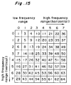
- Fig. 15 shows a second example of the order of the transmission of the quantized values by the transmission unit.
- the orthogonally transformed components are encoded in the order of the numbers shown in Fig. 15 from the lowest frequency component in the horizontal direction and the vertical direction in the small block and are transmitted, the coded word after the quantized value representing the highest frequency of the non 0 quantized values are replaced by the code representing the end of transmission.
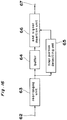
- Fig. 16 shows a second example of the transmission unit. In Fig.
- 62 denotes an input terminal, 63 a rearranging unit, 64 a buffer, 65 a final portion detecting unit, 66 a end signal insertion unit, and 67 an output terminal.
- the quantized values inputted from the input terminal 62 are rearranged in the order shown in Fig. 15 in the rearranging unit 63 and further inputted in the buffer 64.
- the final portion detecting unit 65 detects the position of the non 0 final quantized value among the quantized values rearranged.
- the final consecutive quantized 0s are replaced by the end signal in the end signal insertion unit 66 according to the information from the final portion detecting unit 65.
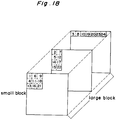
- Fig. 17 shows an example of the transmission order by a third example of the transmission unit.
- Fig. 17 is an example in which the large block consists of three small blocks. In the respective small blocks, the left upper portions represent the low frequency range of the orthogonal components and the right lower portions represent the high frequency range of the orthogonal components.
- the respective numeric characters in Fig. 17 show the transmission order of the orthogonal components in the position. The respective components are transmitted sequentially from the lowest components in the large block basis.
- the third example of the transmission unit can be realized by rearranging the large blocks in the rearranging unit 63 in Fig. 16.
- the transmission order in the third example may be applied to the first example of the transmission unit.
- Fig. 18 shows an example in which the third example of the transmission order is applied in the first example of the transmission unit.
- data transmission is made from the low frequency range in the large block basis, with only the components surrounded by the rectangular shape in the transmission range. In this case it is possible to transmit the transmission range separately therefore it is not necessary to attach the end signal.
- variable length coding unit denotes an input terminal, 69 a ROM (read only memory), and 70 an output terminal.
- the quantized values inputted from the input terminal 68 are converted to the variable length codes in the ROM 69 and outputted to the output terminal 70.
- An example of the variable length codes is explained hereinafter.
- variable length codes such code as the code length is 1 bit for the quantized value 0 is used. Namely the code length Mi for the quantized value Ri is expressed.
- variable length codes as mentioned above facilitates to estimate the data value as explained later.
- Table 2 shows the second example of the variable length coding.
- X is assigned binary value of 1 bit.
- the code length can be calculated easily.
- variable length codes in the table 2 the portion ⁇ 128 - 255 may be changed as 11111111XXXXXX.
- Table 2 quantized value variable length code 0 0 1 10X ⁇ 2 - 3 110XX ⁇ 4 - 7 1110XXX ⁇ 8 - 15 11110XXX ⁇ 16 - 31 111110XXXXX ⁇ 32 - 63 1111110XXXXX ⁇ 64 -127 11111110XXXXXXX ⁇ 128 -255 111111110XXXXXXXX.
- S is a bit for the sign of plus and minus and X7 to X0 represent binary value of the absolute value of the quantized values.
- X7 is the most significant position and X0 is the least significant position.
- the quantized values represented by 9 bits are encoded by the variable length code according to the rule shown in the table 3. However, in the present example, it can be encoded into the variable length code without any complicated calculation. Therefore, it is possible to encode without ROM shown in Fig. 19.
- variable length code 1 100X ⁇ 2 - 5 101XXX ⁇ 6 - 21 110XXXX ⁇ 22 - 53 1110XXXX +54 -181 1111XXXXXXXX.
- the code length it is possible to estimate the code length by only the front half of the code word.
- the word synchronization can be maintained so long as no error occurs at the from half of code words representing the code length even if there occurs any errors in the transmission path.
- decoding can be made with a relatively simple circuit arrangement.
- the fourth example of the variable length coding unit is explained. Almost all components of the orthogonally transformed components are 0, therefore, the probability of consecutive generation of 0s of the quantized values is high. To encode the length of the consecutive 0s of the quantized values into the run length code enables to compress the data amount. To encode the length of the consecutive 0s of the quantized values and the non 0 quantized value appearing first after the consecutive 0s in a code word enables to compress the data amount. This coding method is referred as 2 dimension encoding hereinafter.
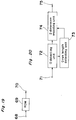
- the fourth example is explained with reference to Fig. 20.
- 71 denotes an input terminal, 72 a detecting unit, 73 a 0 run length detecting unit, 74 a 2 dimension encoding unit, and 75 an output terminal.
- the quantized values inputted from the input terminal 71 are subjected to the detection whether or not each of the quantized value is 0 in the 0 detecting unit 72. If the quantized value is 0, the run length value summed in the 0 run length detecting unit 73 is added by 1.
- 2 dimension encoding is performed by the non 0 quantized value thus detected and the 0 run length value in the 2 dimension encoding unit 74, whereby the 2 dimension code is outputted to the output terminal 75, while the run length value summed in the 0 run length detecting unit 73 is reset.
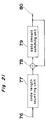
- 76 denotes an input terminal, 77 a code length counting unit, 78 an adder, 79 a data amount summing unit,and 80 an output terminal.
- the example shown in Fig. 21 is a circuit for one of the quantizer units.
- the orthogonally transformed component inputted from the input terminal 76 is applied to the code length counting unit 77 in which the code length of the quantized value when the quantized value is converted to the variable length code is calculated.
- the code length obtained in the code length counting unit 77 is added to the data amount sum before the quantization of the quantized value in the adder 78 and again the added data is inputted to the data amount summing unit 79.
- the code length counting unit 77 may be composed by a ROM simply. It is noted that in order to improve the data compression efficiency, not all of the signals are transmitted by the transmission unit according to the present invention. For this purpose it is necessary to detect the signals to be transmitted and to count the data amount of the data to be transmitted.
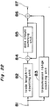
- FIG. 22 A second example of the data amount estimating unit is explained with reference to Fig. 22.
- detection of the signal to be transmitted and counting of the data amount are performed simultaneously.
- 81 denotes an input terminal, 82 a (code length -1) counting unit, 83 a transmission range counting unit, 84 an adder, 85 a data amount summing unit, 86 an adder, and 87 an output terminal.
- the orthogonally transformed components are applied to the (code length -1) counting unit 82 and the value of (code length -1) is calculated therein.
- the output of the (code length -1) counting unit 82 is added to the data amount of the (code length -1) of the previous (code length -1) data amount whereby the data amount of the total value is applied again to the data amount summing unit 85. Simultaneously in the transmission range counting unit 83, the code word number of the code words to be transmitted is counted and the counted value is added to the sum of the (code length -1) outputted from the data amount summing unit 85 in the adder 86, and further outputted to the output terminal 87.
- the first variable length coding unit makes code length as 1 for the 0 quantized value, therefore the value of the (code length -1) is 0.
- the sum of the (code length -1) for the all input signals and the code words to be transmitted is equal to the sum of the code length of the signal to be transmitted. Therefore the calculation of the data amount and the calculation of the transmission range can be made simultaneously, it becomes possible to decrease the time of the data amount estimation to half of the time necessary in the first example of the data amount estimating unit.
- Fig. 23 shows a third example of the data amount estimating unit which is applied to the arrangement using the second example of the variable length coding unit.
- 88 denotes an input terminal, 89 a figure number counting unit, 90 a transmission range counting unit, 91 an adder, 92 a figure number summing unit, 93 a multiplier, 94 an adder,and 95 an output terminal.
- the figure number counting unit 89 calculates the figure number of the absolute value of the quantized value of the orthogonally transformed components applied to the input terminal 88.
- the output of the figure number counting unit 89 is added in the adder 91 to the total value of the respective figure numbers that has been summed for the previous signals before the present signal outputted from the figure number summing unit 92 and the summed value is inputted again to the figure number summing unit 92 simultaneously in the transmission range counting unit 90 the number of the coded words to be transmitted is calculated and the calculated number is added to the multiplied twice in the multiplier 93 and outputted to the output terminal 95.
- the code length is expressed by twice the figure number of the quantized value +1, therefore the data amount can be estimated easily.
- 96 denotes an input terminal, 97 a dividing unit, 98 a quntizing range input terminal, 99 a rounding unit, 100 an output terminal.
- the signals inputted from the input terminal 96 are divided in the dividing unit 97 by the quantizing range value applied to the quantizing range input terminal 98 and the output of the dividing unit 97 is rounded by the rounding unit 98 and is outputted to the output terminal 100.
- the arrangement in the example is equivalent to such a device having the same number of different quantizers as the number of the kinds of the quantization range.
- the quantization range is small, the quantized value after the quantization is small and when the quntization range is large, the qunatized value after the quantization is large, therefore, to select the quantization range enables to vary the data amount after the quantization.
- the dividing unit 97 in Fig. 24 may be replaced by a ROM. When ROM is used, the same operation may be performed by inputting the number representing the quantization range.
- the second example of the quntizing unit is so arranged that large quantization range is assigned for the low frequency components of the DCT transformed components and small quantization range is assigned for the high frequency components of the DCT transformed components.
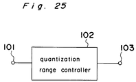
- Fig. 25 shows the second example of the quantization unit.
- 101 denotes an input terminal, 102 a quantization range controller, 103 an output terminal.
- the order of the input signals which is now being quantized is inputted to the quantization controller 102 from the input terminal 101.
- the quantization range controller 102 detects the frequency of the orthogonal components by the order of the input signal. In a case where the input signal is the high frequency component, the quantization range is made large and in a case where the input signal is the low frequency component, the quantization range is made small, the quantized values are outputted to the output terminal 103.
- Fig. 26 shows a third example of the quantizing unit.
- 104 denotes an input terminal, 105 a quantizer, 106 a non 0 (zero) detecting unit, 107 a reversed quantizer, 108 a subtracter, 109 an adder, 110 a summing unit for summing the error of the quantization and 111a and 111b are output terminals.
- Signals fed from the input terminal 104 are quantized in the quantizer 105 and are outputted from the output terminal 111a.
- the outputs of the quantizer 105 are fed to the non 0 detecting unit 106 in which it is detected whether or not the output is 0.
- the non 0 output is fed to the reversed quantizer 107 in which the quantized value is reversed to its original form.
- the reversed value outputted from the reversed quantizer 107 is subtracted by the value of the present input signal in the subtracter 108 and the quantization error is calculated.
- the quantization error of the present input signal is summed, in the adder 109, to the total value of the previous quantization errors of the input signals that have been supplied before the present input signal.
- the total quantization error (to which the quantization error is already added in the adder 109) is again applied to the summing unit 110. In such a manner the total quantization errors of one small block are summed and outputted from the output terminal 111b.
- an average value of the quantization error of non 0 quantized values of every small block is calculated and is outputted with the quantized value.
- the quantization errors in the orthogonal transformation are often uneven in the small block basis. Therefore, to calculate the quantization errors for every block and to use the data of the quantization error to correct the decoded values at the time of the decoding enables to improve the quantization distortion.
- the signals representing the quantization error for the small block transmitted at this time can be represented by a few bits, increment of the data amount is very small.
- a fourth example of the quantizing unit signals situated on the same positions in the frame direction or field direction are quantized by separate quantizers of different quantizing property for every frame or every field. This can be realized by controlling the rounding unit 99 shown in Fig. 24.
- the arrangement of the fourth example is shown in Fig. 27.
- 112 denotes an input terminal, 113 a rounding unit, 114 a frame number input unit, 115 an output terminal.
- the signals divided by the quantization range and inputted from the input terminal 112 are rounded in the rounding unit 113 according to the frame number inputted from the frame number input terminal 114 and are outputted to the output terminal 115.
- the way of rounding is varied every consecutive frames.
- the quantization error can be cancelled at time of decoding. Therefore, in the moving picture the motion of which is small, it is possible to decrease the quantization error.
- the quantization error is different field to field or frame to frame, the distortion is scattered time to time thereby decreasing the block distortion.
- the quantization property is varied by varying the way of rounding, there may vary the quantization property by adding different offset values field to field or frame to frame.
- the first example of the quantizer selecting unit operates in such a manner as described hereinafter. Namely, when there are m candidate quantizers, data amount is estimated for such a case that if quantization is performed using about m/2 th quantizer. When the estimated data amount is larger than transmittable value, the candidate quantizers are limited to such quantizers that produces the data amount smaller than the data amount produced by the previously selected quantizer. To the contrary, if the estimated data amount smaller than the transmittable data value the candidate quantizers are limited to such quantizers which produce the data amount larger than the date amount produced by the previously selected quantizer. By this way the number of the candidate quantizers is decreased by 1/2 every estimation and repeating the above operation optimum quantizers can be decided.
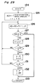
- a flow chart of Fig. 28 An example of process mentioned above is shown in a flow chart of Fig. 28.
- 116 denotes a start step
- 118 a third quantization estimation 119 and 120 are overflow detection
- 121 a first quantization output
- 123 a third quantization output there are provided three quantizing units, larger quantized values are outputted in the order of the third quantization, second quantization and first quantization for the same input value.
- the second qnantization estimation is made in the step 117 using the second quantization for the input value.
- the process goes to the step 119 in which it is detected whether or not the data amount obtained in the second quantiation step 117 exceeds the transmittable limit.
- the process goes to the step 121 to select the first quantization and goes to end.
- the process goes to the step 118 in which the data amount is estimated using the third quantization and estimation.
- the process goes to the step 120 in which it is detected whether or not the data amount quantized in the third quantization exceeds the transmittable limit.
- the process goes to the step 122 and the second quantization is selected and the process goes to end.
- the process goes to the step 123 in which the third quantization is performed and going to the end.
- the quantizer selecting unit it is possible to decrease greatly the calculation amount for the data amount estimation. Also in the present example, a quantizer which produces the maximum data amount which does not exceed the upper transmittable limit, there may be selected a quantizer which produces the minimum data amount which does not fall the lower transmittable limit.
- the small blocks contained in one large block is divided in two by the front half and rear half with the boundary of jth small block counted from the front, and two quantizers included in the divided groups which quantizers produce the nearest quantized data amount.
- the order number i and j of the used quantizer are coded and transmitted.
- only two kinds of the quantizer unit are used in one large block.
- the two kinds of the quantizers are selected from the groups of the front half and the rear half divided in the large block. Therefore the information representing what quantizer is used is expressed only by the boundary of the front half and the rear half, that is small j, the information to be transmitted can be made small.
- Table 4 0 1 2 ... j ... 23 . 0 S(0,0) S(0,1) S(0.2) ... S(0,j) ... S(0,23) 1 S(1,0) S(1,1) S(1,2) ... S(1,j) ... S(1,23) i S(i,0) S(i,1) S(i,2) ... S(i,j) ... S(i,23) 7 S(7,0) S(7,1) S(7,2) ... S(7,j) ... S(7,23) .
- the optimum values i and j are calculated according to the process shown in Fig. 29 using the data shown in the table 4.
- the process goes to the step 129 in which it is detected whether or not the value j is 24, in case of not 24 the process goes to the step 126.
- step 131 it is detected whether or not the value i is 8, in case of not 8 the process goes to the step 126.
- the values i and j can be calculated. Since the values i and j can be expressed by 3 bits and 5 bits, the information what quantizer is used can be transmitted by 8 bits for the large block.
- the third example of the quantizer selecting unit is arranged to operate as the following manner.
- the quantizer of which quantization width is small is used for the small block which produces relatively large maximum value, while the quantizer of which quantization width is small is used for the small block which produces relatively small maximum quantized value.
- the quantized values are transmitted with the information representing the used quantizers for quantizing the data of the respective small blocks.
- 134 denotes an input terminal, 135 a max.value detector, 136 a max.value sorter, 137 an output terminal.
- the orthogonal component inputted from the input terminal 134 is applied to the max. value detector in which the maximum value of the orthogonal component is detected every small block.
- the max. value sorter 136 the order of the small blocks is calculated so that the maximum values of the respective small blocks are lined up in the order from the larger value to the small value. In this manner, the respective small blocks are arranged in the order of the larger dynamic range.
- two quantizers are assigned to the respective small blocks in a similar manner as mentioned in the second example of the quantizer selecting unit.
- a fourth example of the quantizer selecting unit is arranged to select the quantizers for processing the brightness signals and two color difference signals.
- the quantizer selecting unit is arranged to select either a quantizer of relatively large quantization range range for the signals which are hard to recognize visual picture deterioration and a quantizer of relatively small quantization range for the signals which are easy to recognize visual picture deterioration.
- 138 denotes a brightness signal input terminal, 139 a first color difference signal input terminal, 140 a second color difference signal input terminal, 141 a re-arranging unit, 142 an output terminal.
- the respective orthogonal transformed components of the brightness signals, the first color difference signals and the second color difference signals inputted form the respective input terminals 138, 139 and 140 have their signal order re-arranged in the re-arranging unit 141 in such a order that the visual recognition of the picture deterioration is easier.
- the input signals are re-arranged in the order as described above.
- the actual re-arranging operation can be performed in the above large blocking unit.
- the re-arranged small blocks enable to select the quantizers in the same operation as described in the second example of the quantizer selecting unit.
- Fig. 32 is a block diagram of a coding unit according to the present invention, in which 143 denotes an input terminal, 144 a prefilter, 145 an orthogonal transformation coding unit, 146 an output terminal.
- the frequency range of the input signals is limited by the prefilter 144
- the signals of which frequency is limited are coded by the orthogonal transformation coding unit and are outputted to the output terminal 146.
- Fig. 33 is a block diagram of the decoding unit of the present invention in which 147 denotes an input terminal, 148 a decoding unit for decoding the signals outputted from the orthogonal transformed coding device of the present invention, 149 a rear filter, 150 an output terminal.
- the coded words inputted from the input terminal 147 are decoded by the orthogonal transformed decoding unit 148.
- the signals decoded are outputted to the output terminal 150 through the rear filter 149 in which the frequency range of the decoded signals are limited.
- the frequency range of the decoded signals as mentioned above, it becomes possible to improve picture deterioration such as block distortion due to the data compression.
- the limited range cut at the time of coding can be reproduced by the rear filter having an inverted band pass property of the prefilter.
- a first example of the prefilter depress the high frequency components of the vertical, horizontal or skew components.
- the quantized values representing the high frequency components of the vertical, horizontal skew components become 0, the data amount can be greatly compressed. Since the distortion of the high frequency range signals are hard to recognize visually, by using the prefilter mentioned above, it is possible to decrease the data amount preventing the picture deterioration.
- a second example of the prefilter operates to divide the input signals four ranges of low range of horizontal and vertical components, horizontal for the high range and vertical for the low range, horizontal for the low range and vertical for the high range and horizontal and vertical for the high frequency and data amounts in the respective ranges are compressed independently and the compressed data of the respective ranges are added.
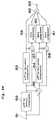
- the second example of the prefilter is explained with reference to Fig. 34, in which 151 denotes an input terminal of the prefilter, 152 a low pass filter for the vertical component (referred to as LPF hereinafter), 153 and 154 are LPF for horizontal components.
- 156, 157 and 158 denote subtracters, 159, 160, 161 denote data compressors, 162 denotes an adder and and 163 denotes an output terminal.
- the signals inputted from the input terminal 151 are converted to the low frequency component by the vertical LPF 152 and the output of which is subtracted from the input signals in the subtracter 156, whereby the output of the vertical LPF 153 represent the low frequency component in the vertical direction of the input signals and the output of the subtracter 156 represents the high frequency components in the vertical direction of the input signals.
- the two signals mentioned above can be divided further in the horizontal direction.
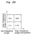
- Fig. 35 shows the two dimension frequency range dividing method.
- the output of the horizontal LPF 154 in Fig. 34 is shown by the area LL in Fig. 35
- the output of the subtracter 157 in Fig. 34 is shown by the area LH in Fig.
- the output of the horizontal LPF 155 in Fig. 34 is shown by the area HL and the output of the subtracter 158 in Fig. 34 is shown by the area HH in Fig. 35.
- the four ranges divided on the two dimensional plane except for the component LL are compressed in the data compressors 159, 160 and 191.
- the respective compressed components are added in the adder 162, and restored in one signal and outputted from the output terminal 43.
- the data compression can be made efficiently matching with the human eyes property. Specifically, by compressing greatly the data in the area HH where the picture deterioration is hard to be recognized, the data amount can be efficiently decreased.
- the third example of the prefilter performs non linear compression in the respective areas in the second prefilter.
- the human eyesight is not sensitive for the amplitude distortion of the high frequency range. Therefore, the greater the amplitude of the component, the larger the compression. In this manner it is possible to concentrate the distortion to the components having the greater amplitude in the high frequency components.
- the fourth example of the prefilter is provided with a suitable threshold value in the respective divided ranges and the signals smaller than the threshold values are rounded. According to the human's eyesight, since the small amplitude signals in the high frequency range are recognized as noise, such small components can be neglected. By eliminating such small components of smaller than the threshold value, amount of unnecessary information can be decreased.
- the fifth example of the prefilter is adapted to control the frequency property of the prefilter in response to the quantized information of the orthogonal transformed components.
- a fact that a quantizer of large quantizing range is selected at the time of orthogonal transformed coding shows that the amount of the input information is large and the distortion due to the data compression is large.
- a fact that a quantizer of small quantizing range is selected shows that the input information is small and distortion due to the data compression is small. Therefore, if the selected quantization range in the past is large, the limitation by the prefilter is enhanced to decrease the frequency limitation.
- the limitation by the prefilter is reduced to decrease the distortion by the prefilter, whereby for the picture having small information amount, the picture information is coded with higher fidelity and for the picture with greater amount of the information, the data amount can be compressed preventing the visual picture quality deterioration.
- a first example of the rear filter compresses or expands the high frequency components in the horizontal direction, vertical direction or skew direction of the input signals.
- the effect of the quantization appears as the block distortion between the small blocks. It is possible to decrease the block distortion by compressing the high frequency components in the boundary between the small blocks by the rear filter.
- the frequency range is limited by the prefilter at the time of coding, it is possible to reproduce the limited range by expanding the high frequency components by the rear filter.
- a second example of the rear filter filters using the signals between the consecutive frames or consecutive fields, whereby it is possible to construct the filter suppressing the differential signals between the frames or fields. By this arrangement, it is possible to decrease distortion due to the data compression in the small motion picture.
- a third example of the rear filter divides the input signals into four regions consisting of low frequency range for the horizontal component and vertical component, high frequency region for the horizontal component and low frequency region for the vertical component, low frequency region for the horizontal component and high frequency region of the vertical component and high frequency region for both of the horizontal component and vertical component, whereby the respective signals in the four regions are independently linearly data compressed and expanded and the signals in all of the regions are added.
- the arrangement to perform such operation is formed in such an arrangement as shown in Fig. 34. By the arrangement mentioned above, it is possible to eliminate the distortion due to the data compression matching with the human's eye property. If the second example of the prefilter is used, it is possible to reproduce the picture signals contained in the limited frequency range by using the rear filter of inverted property of the prefilter.
- a fifth example of the rear filter is arranged to use non linear expansion to expand the respective four ranges in the third example of the rear filter. If the high frequency range is linearly expanded as made in the third example, the block distortion may be expanded. To prevent the drawback, the non linear expansion is employed so that the small high frequency component is not expanded but only the large high frequency component is expanded. In general, since the amplitude component of the block distortion is small, it becomes possible to reproduce the signals without amplifying the block distortion.
- a fifth example of the rear filter is provided with a threshold value after the frequency division in the second, third or fourth examples and the values smaller than the threshold value are rounded to 0.
- the small high frequency components are recognized as noise, effect of elimination of such small high frequency component is few even if such components are eliminated.
- To eliminate the component smaller than the threshold value enables to decrease the amount of the unnecessary information. Also the block distortion can be eliminated.
- a sixth example of the rear filter controls the frequency property of the rear filter in response to the quantization information of the transmitted data.
- a quantizer of large quantization range is used at the time of quanization and coding, this means that the distortion due to the data compression is large. Therefore, to enhance the frequency range limitation enables to decrease the effect of the quantization distortion.
- the qauntizer of small quantization range is used, this means that the distortion due to the data compression is small. Therefore, to decrease the frequency range limitation of the rear filter enables to decrease the distortion by the rear filter.
- the fifth example of the prefilter is used at the coding, it is possible to estimate the prefilter in use by the selected quantizer. Therefore, it is possible to reproduce the limited frequency component by using the rear filter having the reversed property of the used prefilter.
Claims (35)
- Einrichtung zur orthogonalen Transformationskodierung miteiner einen großen Block bildenden Einrichtung (14) zum Zusammensetzen von Abtastwerten der Eingangssignale, um einen großen Block der abgetasteten Eingangssignale zu bilden,einer einen kleinen Block bildenden Einrichtung (15) zum Bilden kleiner Blöcke durch Teilen der Abtastwerte der Eingangssignale in benachbarte Abtastwerte,einer orthogonalen Transformationseinrichtung (16) für die orthogonale Transformation der Abtastwerte in dem kleinen Block für jeden kleinen Block in einem großen Block, wenn die in einer vorbestimmten Anzahl zusammengefaßten kleinen Blöcke als großer Block genannt werden,einer Quantisierungseinrichtung (20), welche eine Vielzahl von Quantisierer umfaßt, von denen jeder die orthogonal transformierten Bestandteile quantisiert, die durch die orthogonale Transformationseinrichtung (16) zur Verfügung gestellt werden,einer Datenmengenschätzungseinrichtung (18), um die Datenmenge zu schätzen,einer Auswahleinrichtung (19) zur Auswahl eines optimalen Quantisierers in der Quantisierungseinrichtung (20) für jeden kleinen Block entsprechend dem Ergebnis der Schätzung der Datenmenge eines jeden kleinen Blocks durch die Datenmengenschätzungseinrichtung (18),einer Kodierungseinrichtung (21) zur Umwandlung der in der Quantisierungseinrichtung (20) erhaltenen Werte in kodierte Daten variabler Länge, undeiner Übertragungseinrichtung (22) zur Übertragung der von der Quantisierungseinrichtung (20) erhaltenen Kodewörter variabler Länge und vonder ausgewählten Quantisierungseinrichtung (20) durch eine feste Länge für jeden großen Block zugehörigen Informationen und dergleichen,dadurch gekennzeichnet, daßdie Datenmengenschätzungseinrichtung (18) eine Vielzahl von Quantisierungseinheiten enthält, von denen jede die gleichen Daten in der Datenmengenschätzungseinrichtung (18) quantisiert und eine Kodelängenzähleinheit (77; 82) beinhaltet, in der die Kodelänge des quantisierten Wertes berechnet wird, wenn der quantisierte Wert in den Kode mit variabler Länge umgewandelt wird, so daß die Datenmengenschätzungseinrichtung (18) vorgesehen ist, um die Datenmenge nach der Kodierung in variabler Länge zu schätzen, indem die Kodelänge nach der Quantisierung und der Kodierung in variabler Länge bei jedem kleinen Block für die Vielzahl von Quantisierern in der Quantisierungseinrichtung (20) berechnet wird, unddie Auswahleinrichtung (19) vorgesehen ist, um einen optimalen Quantisierer in der Quantisierungseinrichtung (20) für jeden kleinen Block auszuwählen, so daß die Datenmenge nach der Kodierung in variabler Länge in bezug auf den großen Block zu der zu übertragenden Datenmenge in bezug auf den großen Block, basierend auf der Datenmenge nach der Kodierung in variabler Länge für jeden der kleinen Blöcke paßt.
- Einrichtung zur orthogonalen Transformationskodierung nach Anspruch 1, dadurch gekennzeichnet, daß die einen großen Block bildende Einrichtung vorgesehen ist, um einen großen Block von Fernsehsignalen in einem Feld zu erzeugen.
- Einrichtung zur orthogonalen Transformationskodierung nach Anspruch 1, dadurch gekennzeichnet, daß die einen großen Block bildende Einrichtung einen großen Block einer Vielzahl von aufeinanderfolgenden Feldern der Fernsehsignale erzeugt.
- Einrichtung zur orthogonalen Transformationskodierung nach Anspruch 1, dadurch gekennzeichnet, daß die einen großen Block bildende Einrichtung einen großen Block von Signalen von in einem Bild nebeneinander gestellten Bildelementen erzeugt.
- Einrichtung zur orthogonalen Transformationskodierung nach Anspruch 1, dadurch gekennzeichnet, daß die einen großen Block bildende Einrichtung einen großen Block durch die Zusammensetzung von einer Vielzahl kleiner Blöcke erzeugt, die in verschiedenen Bereichen in einem Bild angeordnet sind.
- Einrichtung zur orthogonalen Transformationskodierung nach Anspruch 1, dadurch gekennzeichnet, daß die einen großen Block bildende Einrichtung den großen Block in der Weise erzeugt, daß für den Fall, in dem sich die Eingangssignale aus Helligkeitssignalen und Farbdifferenzsignalen zusammensetzen, alle großen Blöcke die Helligkeitssignale und die Farbdifferenzsignale oder R-, G- und B-Signale im wesentlichen gleichen Verhältnisses enthalten.
- Einrichtung zur orthogonalen Transformationskodierung nach Anspruch 1, dadurch gekennzeichnet, daß die einen kleinen Block bildende Einrichtung einen kleinen Block erzeugt, der aus den Signalen aufgebaut ist, die lediglich in einem Feld des Fernsehsignals enthalten sind.
- Einrichtung zur orthogonalen Transformationskodierung nach Anspruch 1, dadurch gekennzeichnet, daß die einen kleinen Block bildende Einrichtung einen kleinen aus den Signalen einer Vielzahl von Feldern eines Fernsehsignals zusammengesetzten Block erzeugt.
- Einrichtung zur orthogonalen Transformationskodierung nach Anspruch 1, dadurch gekennzeichnet, daß die einen kleinen Block bildende Einrichtung einen kleinen Block erzeugt, der sich aus Signalen eines Feldes oder eines Rahmens oder einer Vielzahl von aufeinanderfolgenden Feldern zusammensetzt.
- Einrichtung zur orthogonalen Transformationskodierung nach Anspruch 1, dadurch gekennzeichnet, daß die orthogonale Transformationseinrichtung die Daten in drei Dimensionen einschließlich der horizontalen Richtung, der vertikalen Richtung und der Zeit transformiert.
- Einrichtung zur orthogonalen Transformationskodierung nach Anspruch 1, dadurch gekennzeichnet, daß die Übertragungseinrichtung die quantisierten Werte eines kleinen Blocks in einem Übertragungsbereich neu anordnet, der durch eine Matrix erzeugt ist, deren Ursprung durch die Werte der niedrigsten Frequenzkomponenten mit der Reihenfolge von den niedrigen Frequenzwerten zu den hohen Frequenzwerten in horizontaler und vertikaler Richtung definiert ist, um sämtliche Werte ungleich Null zu umfassen und kodierte Wörter der quantisierten Werte, die nur in der Übertragungsregion enthalten sind und Informationen der Übertragungsregion zu übertragen.
- Einrichtung zur orthogonalen Transformationskodierung nach Anspruch 1, dadurch gekennzeichnet, daß die Übertragungseinrichtung die quantisierten Werte eines kleinen Blocks in einem Übertragungsbereich neu anordnet, der durch eine Matrix gebildet ist, deren Ursprung durch die Werte der niedrigsten Frequenzkomponenten mit der Reihenfolge von den niedrigen Frequenzwerten zu den hohen Frequenzwerten in horizontaler und vertikaler Richtung definiert ist, um sämtliche Werte ungleich Null zu umfassen und kodierte Wörter der quantisierten Werte, die im Übertragungsbereich enthalten sind, von den quantisierten Werten, die die niedrigsten Frequenzkomponenten darstellen, bis zu den quantisierten Werten, die die höchsten Frequenzkomponenten darstellen, in der Reihenfolge von dem kodierten Wort der niedrigsten Frequenzkomponente und ein Endsignal oder eine Information, die die Position des letzten kodierten Wortes darstellt, anstelle der Übertragung der kodierten Wörter zu übertragen, nachdem die höchste Frequenzkomponente ungleich Null übertragen ist.
- Einrichtung zur orthogonalen Transformationskodierung nach den Ansprüchen 11 und 12,
dadurch gekennzeichnet, daß für den Fall, daß n kleine Blöcke in dem großen Block enthalten sind, die Übertragungseinrichtung die kodierten Wörter von dem kodierten Wort, welches die niedrigste Frequenzkomponente repräsentiert, auf der Grundlage des großen Blocks in folgender Weise überträgt:das erste kodierte Wort im ersten kleinen Blockdas erste kodierte Wort im zweiten kleinen Block
.
.
.das erste kodierte Wort im n-ten kleinen Blockdas zweite kodierte Wort im ersten kleinen Block
.
. - Einrichtung zur orthogonalen Transformationskodierung nach Anspruch 1, dadurch gekennzeichnet, daß die in variabler Länge kodierende Einrichtung den quantisierten Wert mit der Länge 1 für den quantisierten Wert Null kodiert.
- Einrichtung zur orthogonalen Transformationskodierung nach Anspruch 1, dadurch gekennzeichnet, daß die in variabler Länge kodierende Einrichtung die quantisierten Werte mit der Länge 2K + 1 oder 2K für die Anzahl von K-Stellen des absoluten Wertes des quantisierten Wertes kodiert.
- Einrichtung zur orthogonalen Transformationskodierung nach Anspruch 1, dadurch gekennzeichnet, daß die in variabler Länge kodierende Einrichtung in einer Weise kodiert, daß die vordere Hälfte des kodierten Wortes die Kodelänge repräsentiert.
- Einrichtung zur orthogonalen Transformationskodierung nach Anspruch 1, dadurch gekennzeichnet, daß die in variabler Länge kodierende Einrichtung die quantisierten Werte in der durch die Datenübertragungseinrichtung definierten Reihenfolge in der Weise kodiert, daß die Anzahl der Nullen der quantisierten Werte und der nicht Null quantisierten Werte, die zuerst erscheinen, durch ein kodiertes Wort ausgedrückt werden.
- Einrichtung zur orthogonalen Transformationskodierung nach Anspruch 1, dadurch gekennzeichnet, daß die Datenmengenschätzungseinrichtung die Datenmenge der kodierten Daten durch Addition der Kodelängen der durch die Übertragungseinrichtung zu übertragenden kodierten Daten berechnet.
- Einrichtung zur orthogonalen Transformationskodierung nach Anspruch 14, dadurch gekennzeichnet, daß die Datenmengenschätzungseinrichtung die Datenmenge, wenn die in variabler Länge kodierende Einrichtung gemäß Anspruch 14 benutzt wird, gemäß der folgenden Gleichung berechnet

M die Anzahl der zu übertragenden quantisierten Werte ist. - Einrichtung zur orthogonalen Transformationskodierung nach Anspruch 1 5, dadurch gekennzeichnet, daß die Datenmengenschätzungseinrichtung die Datenmenge, wenn die in variabler Länge kodierende Einrichtung gemäß Anspruch 15 benutzt wird, gemäß der Gleichung 2 × Σ Ki + M berechnet,wobei Ki die Anzahl der Stellen des absoluten Wertes der quantisierten Werte des i-ten Quantisierers undM die Anzahl der zu übertragenden quantisierten Werte ist.
- Einrichtung zur orthogonalen Transformationskodierung nach Anspruch 1, dadurch gekennzeichnet, daß die Quantisierungseinrichtung eine Vielzahl von Quantisierern enthält, die jeweils einen unterschiedlichen Quantisierungsbereich haben.
- Einrichtung zurorthogonalen Transformationskodierung nach Anspruch 21, dadurch gekennzeichnet, daß die Quantisierer für die hochfrequenten orthogonaltransformierten Komponente einen weiten Quantisierungsbereich und die Quantisierer für die niederfrequenten orthogonaltransformierten Komponenten einen schmalen Quantisierungsbereich aufweisen.
- Einrichtung zur orthogonalen Transformationskodierung nach Anspruch 21, dadurch gekennzeichnet, daß die Quantisierungseinrichtung den Durchschnitt des Quantisierungsfehlers der quantisierten Werte, mit Ausnahme von Null, für jeden kleinen Block zur Zeit der Quantisierung überträgt und zum Zeitpunkt der Dekodierung die rückgeführten quantisierten Werte mit dem Durchschnittswert des Quantisierungsfehlers korrigiert.
- Einrichtung zur orthogonalen Transformationskodierung nach Anspruch 21, dadurch gekennzeichnet, daß die Quantisierungseinrichtung die Signale an der gleichen Position auf der Bildebene der Felder oder Rahmen mit Quantisierern quantisiert, die einen unterschiedlichen Quantisierungsbereich aufweisen.
- Einrichtung zur orthogonalen Transformationskodierung nach Anspruch 1, dadurch gekennzeichnet, daßdie Quantisiererauswahleinrichtung folgende Schritte ausführt:die Datenmenge zu schätzen, die durch den Quantisierer erhalten wird, der die m/2-te Datenmenge quantisierter Werte produziert, wenn es m Kandidatenquantisierer gibt,für den Fall, daß die geschätzte quantisierte Datenmenge größer als die übertragbare Datenmenge ist, nur die Quantisierer auszuwählen, die die Datenmenge produzieren, welche kleiner als die Datenmenge ist, die durch die Quantisiererer produziert wird, welche der Datenschätzung unterworfen worden sind, und im umgekehrten Fall, daß die geschätzte, quantisierte Datenmenge kleiner als die übertragbare Datenmenge ist, nur die Quantisierer auszuwählen, deren produzierte Datenmenge größer als die Datenmenge ist, die durch die Quantisierer produziert wird,welche der Datenschätzung unterworfen worden sind,wobei die Anzahl der Kandidatenquantisierer auf die Hälfte reduziert wird und der vorstehend beschriebene Ablauf wiederholt wird, um den optimalen Quantisierer auszuwählen.
- Einrichtung zur orthogonalen Transformationskodierung nach Anspruch 1, dadurch gekennzeichnet, daß die Quantisiererauswahleinrichtung die folgenden Schritte ausführt,die in einem großen Block enthaltenen kleinen Blöcke in eine vordere Hälfte, die Quantisierer von der führenden bis zur j-ten Stelle umfaßt, und eine hintere Hälfte zu teilen,einen Quantisierer von der vorderen Hälfte und hinteren Hälfte, der den nächstkommenden quantisierten Wert produziert, auszuwählen, undden quantisierten Wert und die Information zu übertragen, welche die Quantisierer und die Nummer j repräsentiert.
- Einrichtung zur orthogonalen Transformationskodierung nach Anspruch 1, dadurch gekennzeichnet, daß die Quantisiererauswahleinrichtung die folgenden Schritte durchführt:den Maximalwert der absoluten Werte der orthogonaltransformierten Werte in jedem kleinen Block zu erfassen,einen Quantisierer von großer Quantisierungsweite für den kleinen Block mit einem großen maximalen quantisierten Wert und einen Quantisierer von kleiner Quantisierungsweite für den Block mit einem kleinen maximalen Quantisierungswert auszuwählen, unddie kodierten Daten, die einen der genutzten Quantisierer repräsentieren, und Informationen zu übertragen, die darstellen, welcher kleine Block welchen Quantisierer benutzt.
- Einrichtung zur orthogonalen Transformationskodierung nach Anspruch 1, dadurch gekennzeichnet, daß für das Helligkeitssignal und zwei Farbdifferenzsignale die Quantisiererauswahleinrichtung einen Quantisierer auswählt, der eine große Quantisierungsweite für die Signale besitzt, bei denen eine visuelle Bildverschlechterung schwer zu erkennen ist, und einen Quantisierer mit schmaler Quantisierungsweite für Signale auswählt, bei denen eine visuelle Bildverschlechterung leicht zu erkennen ist.
- Einrichtung zur orthogonalen Transformationskodierung nach Anspruch 1, dadurch gekennzeichnet, daß die Einrichtung weiterhin mindestens irgendeinen Vorfilter, der vor der einen großen Block bildenden Einrichtung vorgesehen ist, und ein hinteres Filter aufweist, der für die wiedergegebene Ausgabe zur Zeit der Dekodierung vorgesehen ist.
- Einrichtung zur orthogonalen Transformationskodierung nach Anspruch 29, dadurch gekennzeichnet, daß das Vorfilter und das hintere Filter die vertikalen Komponenten, horizontalen Komponenten oder schrägen Komponenten des Signals komprimieren oder expandieren.
- Einrichtung zurorthogonalen Transformationskodierung nach Anspruch 30, dadurch gekennzeichnet, daß das Vorfilter oder das hintere Filter die Signale in vier Bereiche einteilten, welche aus Niederfrequenzbereichen in der horizontalen Richtung und der vertikalen Richtung, einen Niederfrequenzbereich in der horizontalen Richtung und einen Hochfrequenzbereich in der vertikalen Richtung, einen Hochfrequenzbereich in der horizontalen Richtung und einen Niederfrequenzbereich in der vertikalen Richtung und Hochfrequenzbereiche in beiden horizontalen und vertikalen Richtungen bestehen, und die entsprechenden Regionen komprimieren oder expandieren und die entsprechenden Regionen addieren.
- Einrichtung zur orthogonalen Transformationskodierung nach den Ansprüchen 30 und 31,
dadurch gekennzeichnet, daß das Vorfilter und das hintere Filter mit Schwellwerten nach der Teilung der Signale in die vier Bereiche und Rundung der Signale auf Null, wenn der Ausgangswert von einem Bereich kleiner als der Schwellwert ist, versehen werden. - Einrichtung zur orthogonalen Transformationskodierung nach den Ansprüchen 30, 31 und 32,
dadurch gekennzeichnet, daß das Vorfilter und das hintere Filter die Weite des Kompressionsbandes oder des Schwellwertes in Abhängigkeit der zur Zeit der Kodierung ausgewählten Quantisierungseinrichtung ändern. - Einrichtung zur orthogonalen Transformationskodierung nach den Ansprüchen 29 bis 33,
dadurch gekennzeichnet, daß das hintere Filter die Signale zwischen den Rahmen oder Feldern filtert. - Einrichtung zur orthogonalen Transformationskodierung nach Anspruch 1, dadurch gekennzeichnet, daß die Übertragungseinrichtung die Signale nach der Reihenfolge der Wichtigkeit zur Zeit der Reproduktion überträgt.
Applications Claiming Priority (6)
| Application Number | Priority Date | Filing Date | Title |
|---|---|---|---|
| JP147891/89 | 1989-06-09 | ||
| JP14789189A JPH0787585B2 (ja) | 1989-06-09 | 1989-06-09 | 高能率符号化装置 |
| JP1203285A JPH0366228A (ja) | 1989-08-04 | 1989-08-04 | ブロック符号化装置と復号化装置 |
| JP203285/89 | 1989-08-04 | ||
| JP4152/90 | 1990-01-11 | ||
| JP2004152A JPH03209919A (ja) | 1990-01-11 | 1990-01-11 | ブロック符号化装置 |
Publications (3)
| Publication Number | Publication Date |
|---|---|
| EP0401854A2 EP0401854A2 (de) | 1990-12-12 |
| EP0401854A3 EP0401854A3 (de) | 1992-07-29 |
| EP0401854B1 true EP0401854B1 (de) | 1997-08-06 |
Family
ID=27276142
Family Applications (1)
| Application Number | Title | Priority Date | Filing Date |
|---|---|---|---|
| EP19900110889 Expired - Lifetime EP0401854B1 (de) | 1989-06-09 | 1990-06-08 | Einrichtung zur orthogonalen Transformationskodierung |
Country Status (3)
| Country | Link |
|---|---|
| EP (1) | EP0401854B1 (de) |
| DE (1) | DE69031198T2 (de) |
| HK (1) | HK1001940A1 (de) |
Families Citing this family (33)
| Publication number | Priority date | Publication date | Assignee | Title |
|---|---|---|---|---|
| US5146324A (en) * | 1990-07-31 | 1992-09-08 | Ampex Corporation | Data compression using a feedforward quantization estimator |
| JP2839339B2 (ja) * | 1990-08-06 | 1998-12-16 | 松下電器産業株式会社 | 直交変換符号化装置および直交変換符号化方法 |
| SG43860A1 (en) * | 1990-09-10 | 1997-11-14 | Mitsubishi Electric Corp | Coding apparatus |
| US5150208A (en) * | 1990-10-19 | 1992-09-22 | Matsushita Electric Industrial Co., Ltd. | Encoding apparatus |
| EP0482888B1 (de) * | 1990-10-25 | 1997-06-04 | Matsushita Electric Industrial Co., Ltd. | Aufzeichnungs- und Wiedergabegerät für Videosignale |
| DE69122595T2 (de) * | 1990-12-27 | 1997-03-20 | Toshiba Kawasaki Kk | Aufzeichnungs- und Abspielgerät |
| EP0493130B1 (de) * | 1990-12-28 | 1997-06-11 | Canon Kabushiki Kaisha | Bildcodierungsgerät mit Optimierung der erzeugten Codemenge |
| EP0498578B1 (de) * | 1991-02-07 | 1999-04-07 | Canon Kabushiki Kaisha | Vorrichtung zum Kodieren von Bildern |
| JP2630085B2 (ja) * | 1991-02-26 | 1997-07-16 | 松下電器産業株式会社 | 記録装置と再生装置 |
| JP3141139B2 (ja) * | 1991-03-13 | 2001-03-05 | 三菱電機株式会社 | 映像音声デジタル記録/再生装置 |
| JP3109854B2 (ja) * | 1991-04-23 | 2000-11-20 | キヤノン株式会社 | 画像符号化方法及び装置 |
| JPH04323960A (ja) * | 1991-04-23 | 1992-11-13 | Canon Inc | 画像符号化装置 |
| JPH0583696A (ja) * | 1991-06-07 | 1993-04-02 | Sony Corp | 画像符号化装置 |
| JP3227674B2 (ja) * | 1991-06-27 | 2001-11-12 | ソニー株式会社 | 動画像符号化装置および方法 |
| WO1993002527A1 (fr) * | 1991-07-19 | 1993-02-04 | Laboratoire De Traitement Des Signaux | Procede de regulation statistique de debit pour la transmission d'images numeriques |
| JP3141896B2 (ja) * | 1991-08-09 | 2001-03-07 | ソニー株式会社 | ディジタルビデオ信号の記録装置 |
| US5530478A (en) * | 1991-08-21 | 1996-06-25 | Kabushiki Kaisha Toshiba | Image data compressing apparatus |
| GB2259421B (en) * | 1991-09-04 | 1995-01-18 | Sony Broadcast & Communication | Image data recording and transmission |
| US5144424A (en) * | 1991-10-15 | 1992-09-01 | Thomson Consumer Electronics, Inc. | Apparatus for video data quantization control |
| US5231484A (en) * | 1991-11-08 | 1993-07-27 | International Business Machines Corporation | Motion video compression system with adaptive bit allocation and quantization |
| MY109399A (en) * | 1992-01-07 | 1997-01-31 | Koninklijke Philips Electronics Nv | Device for processing digital data, and digital video system comprising the device |
| US5349384A (en) * | 1992-01-14 | 1994-09-20 | Sony Corporation | Apparatus and methods for transmitting compressed digital image signals |
| JPH05236427A (ja) * | 1992-02-25 | 1993-09-10 | Sony Corp | 画像信号の符号化装置及び符号化方法 |
| JP3166291B2 (ja) * | 1992-04-03 | 2001-05-14 | ソニー株式会社 | 量子化コントロール回路 |
| US5587806A (en) * | 1993-03-26 | 1996-12-24 | Matsushita Electric Industrial Co., Ltd. | Apparatus for separately recording input coded video signal and important data generated therefrom |
| JP3336754B2 (ja) * | 1994-08-19 | 2002-10-21 | ソニー株式会社 | デジタルビデオ信号の記録方法及び記録装置 |
| WO1996025801A1 (en) * | 1995-02-17 | 1996-08-22 | Trustus Pty. Ltd. | Method for partitioning a block of data into subblocks and for storing and communicating such subblocks |
| KR100188934B1 (ko) * | 1995-08-28 | 1999-06-01 | 윤종용 | 영상 신호 부호화 장치 및 방법 |
| US6266375B1 (en) * | 1997-11-13 | 2001-07-24 | Sony Corporation | Method and apparatus for selecting a quantization table for encoding a digital image |
| US6983073B1 (en) | 1999-01-13 | 2006-01-03 | Gidel Imaging Ltd. | Enhancement of compressed images |
| WO2000042774A1 (en) * | 1999-01-14 | 2000-07-20 | Gidel Imaging Ltd. | Enhancement of compressed images |
| EP1768416A1 (de) * | 2005-09-27 | 2007-03-28 | Matsushita Electric Industrial Co., Ltd. | Frequenzselektive Videocomprimierung und -quantisierung |
| EP1768415A1 (de) * | 2005-09-27 | 2007-03-28 | Matsushita Electric Industrial Co., Ltd. | Adaptive Scanreihenfolge der DCT-Koeffizienten und Übertragung dieser Reihenfolge |
Family Cites Families (6)
| Publication number | Priority date | Publication date | Assignee | Title |
|---|---|---|---|---|
| DE3684047D1 (de) * | 1985-07-02 | 1992-04-09 | Matsushita Electric Ind Co Ltd | Vorrichtung zur blockkodierung. |
| GB8621994D0 (en) * | 1986-09-12 | 1986-10-22 | Crosfield Electronics Ltd | Image processing |
| CA1296430C (en) * | 1986-11-10 | 1992-02-25 | Masahide Kaneko | Encoding system capable of accomplishing a high efficiency by anterior and/or posterior processing to quantization |
| US4920426A (en) * | 1986-11-10 | 1990-04-24 | Kokusai Denshin Denwa Co., Ltd. | Image coding system coding digital image signals by forming a histogram of a coefficient signal sequence to estimate an amount of information |
| NL8700565A (nl) * | 1987-03-10 | 1988-10-03 | Philips Nv | Televisiesysteem waarin aan een transformatiekodering onderworpen gedigitaliseerde beeldsignalen worden overgebracht van een kodeerstation naar een dekodeerstation. |
| US4821119A (en) * | 1988-05-04 | 1989-04-11 | Bell Communications Research, Inc. | Method and apparatus for low bit-rate interframe video coding |
-
1990
- 1990-06-08 DE DE1990631198 patent/DE69031198T2/de not_active Expired - Lifetime
- 1990-06-08 EP EP19900110889 patent/EP0401854B1/de not_active Expired - Lifetime
-
1998
- 1998-02-06 HK HK98100920A patent/HK1001940A1/xx not_active IP Right Cessation
Also Published As
| Publication number | Publication date |
|---|---|
| HK1001940A1 (en) | 1998-07-17 |
| EP0401854A3 (de) | 1992-07-29 |
| EP0401854A2 (de) | 1990-12-12 |
| DE69031198T2 (de) | 1998-03-19 |
| DE69031198D1 (de) | 1997-09-11 |
Similar Documents
| Publication | Publication Date | Title |
|---|---|---|
| EP0401854B1 (de) | Einrichtung zur orthogonalen Transformationskodierung | |
| US5073821A (en) | Orthogonal transform coding apparatus for reducing the amount of coded signals to be processed and transmitted | |
| EP0470773B1 (de) | Vorrichtung zur orthogonalen Transformationskodierung | |
| EP0481768B1 (de) | Kodierungsgerät | |
| US5051840A (en) | Device for coding a picture signal by compression | |
| US5253075A (en) | Image signal coding/decoding system using adaptive quantization | |
| US5063608A (en) | Adaptive zonal coder | |
| EP0385654B1 (de) | Kodiergerät von hoher Wirksamkeit | |
| US6219456B1 (en) | Picture coding apparatus and method thereof | |
| EP0349847B1 (de) | Verfahren und Vorrichtung für die Bilddatenkomprimierung | |
| US4922273A (en) | Compression method of halftone image data | |
| EP0473384B1 (de) | Kodierungsgerät für digitale Bildsignale | |
| US5539468A (en) | Coding device and decoding device adaptive to local characteristics of an image signal | |
| US5446806A (en) | Quadtree-structured Walsh transform video/image coding | |
| EP0553361B1 (de) | Bilddatenkompressionsvorrichtung | |
| EP0480353B1 (de) | Verfahren und Einrichtung zur Datenkompression für Videosignale | |
| US6603813B1 (en) | Video signal coding systems and processes using adaptive quantization | |
| US20020196983A1 (en) | Image encoding apparatus, image encoding method, and recording medium in which image encoding program is recorded | |
| EP0659023B1 (de) | Verfahren und Vorrichtung zur Bilddatenkodierung und -kompression | |
| EP1377065A1 (de) | Bildsignalquantisierungseinrichtung und ihr verfahren | |
| US5416615A (en) | Digital data transmitting apparatus | |
| EP0720375A2 (de) | Einrichtung und Verfahren zur Quantisierung | |
| JPH07236142A (ja) | 高能率符号化装置及び復号化装置 | |
| US5534930A (en) | Method for constructing a quantization pattern codebook | |
| US6408097B1 (en) | Picture coding apparatus and method thereof |
Legal Events
| Date | Code | Title | Description |
|---|---|---|---|
| PUAI | Public reference made under article 153(3) epc to a published international application that has entered the european phase |
Free format text: ORIGINAL CODE: 0009012 |
|
| 17P | Request for examination filed |
Effective date: 19900608 |
|
| AK | Designated contracting states |
Kind code of ref document: A2 Designated state(s): DE FR GB NL |
|
| PUAL | Search report despatched |
Free format text: ORIGINAL CODE: 0009013 |
|
| AK | Designated contracting states |
Kind code of ref document: A3 Designated state(s): DE FR GB NL |
|
| 17Q | First examination report despatched |
Effective date: 19950306 |
|
| GRAG | Despatch of communication of intention to grant |
Free format text: ORIGINAL CODE: EPIDOS AGRA |
|
| GRAH | Despatch of communication of intention to grant a patent |
Free format text: ORIGINAL CODE: EPIDOS IGRA |
|
| GRAH | Despatch of communication of intention to grant a patent |
Free format text: ORIGINAL CODE: EPIDOS IGRA |
|
| GRAA | (expected) grant |
Free format text: ORIGINAL CODE: 0009210 |
|
| AK | Designated contracting states |
Kind code of ref document: B1 Designated state(s): DE FR GB NL |
|
| REF | Corresponds to: |
Ref document number: 69031198 Country of ref document: DE Date of ref document: 19970911 |
|
| ET | Fr: translation filed | ||
| PLBE | No opposition filed within time limit |
Free format text: ORIGINAL CODE: 0009261 |
|
| STAA | Information on the status of an ep patent application or granted ep patent |
Free format text: STATUS: NO OPPOSITION FILED WITHIN TIME LIMIT |
|
| 26N | No opposition filed | ||
| REG | Reference to a national code |
Ref country code: GB Ref legal event code: IF02 |
|
| PGFP | Annual fee paid to national office [announced via postgrant information from national office to epo] |
Ref country code: NL Payment date: 20090615 Year of fee payment: 20 |
|
| PGFP | Annual fee paid to national office [announced via postgrant information from national office to epo] |
Ref country code: DE Payment date: 20090604 Year of fee payment: 20 Ref country code: GB Payment date: 20090603 Year of fee payment: 20 |
|
| REG | Reference to a national code |
Ref country code: NL Ref legal event code: V4 Effective date: 20100608 |
|
| REG | Reference to a national code |
Ref country code: GB Ref legal event code: PE20 Expiry date: 20100607 |
|
| PG25 | Lapsed in a contracting state [announced via postgrant information from national office to epo] |
Ref country code: NL Free format text: LAPSE BECAUSE OF EXPIRATION OF PROTECTION Effective date: 20100608 |
|
| PG25 | Lapsed in a contracting state [announced via postgrant information from national office to epo] |
Ref country code: GB Free format text: LAPSE BECAUSE OF EXPIRATION OF PROTECTION Effective date: 20100607 |
|
| PG25 | Lapsed in a contracting state [announced via postgrant information from national office to epo] |
Ref country code: DE Free format text: LAPSE BECAUSE OF EXPIRATION OF PROTECTION Effective date: 20100608 |
|
| PGFP | Annual fee paid to national office [announced via postgrant information from national office to epo] |
Ref country code: FR Payment date: 20090611 Year of fee payment: 20 |