EP0401764A2 - Anordnung eines optischen Kopfes mit Halbleiter-Laser - Google Patents
Anordnung eines optischen Kopfes mit Halbleiter-Laser Download PDFInfo
- Publication number
- EP0401764A2 EP0401764A2 EP90110638A EP90110638A EP0401764A2 EP 0401764 A2 EP0401764 A2 EP 0401764A2 EP 90110638 A EP90110638 A EP 90110638A EP 90110638 A EP90110638 A EP 90110638A EP 0401764 A2 EP0401764 A2 EP 0401764A2
- Authority
- EP
- European Patent Office
- Prior art keywords
- optical head
- laser beam
- transparent plate
- photodetector
- laser
- Prior art date
- Legal status (The legal status is an assumption and is not a legal conclusion. Google has not performed a legal analysis and makes no representation as to the accuracy of the status listed.)
- Withdrawn
Links
Images


Classifications
-
- G—PHYSICS
- G11—INFORMATION STORAGE
- G11B—INFORMATION STORAGE BASED ON RELATIVE MOVEMENT BETWEEN RECORD CARRIER AND TRANSDUCER
- G11B7/00—Recording or reproducing by optical means, e.g. recording using a thermal beam of optical radiation by modifying optical properties or the physical structure, reproducing using an optical beam at lower power by sensing optical properties; Record carriers therefor
- G11B7/12—Heads, e.g. forming of the optical beam spot or modulation of the optical beam
- G11B7/135—Means for guiding the beam from the source to the record carrier or from the record carrier to the detector
- G11B7/1392—Means for controlling the beam wavefront, e.g. for correction of aberration
-
- G—PHYSICS
- G11—INFORMATION STORAGE
- G11B—INFORMATION STORAGE BASED ON RELATIVE MOVEMENT BETWEEN RECORD CARRIER AND TRANSDUCER
- G11B7/00—Recording or reproducing by optical means, e.g. recording using a thermal beam of optical radiation by modifying optical properties or the physical structure, reproducing using an optical beam at lower power by sensing optical properties; Record carriers therefor
- G11B7/08—Disposition or mounting of heads or light sources relatively to record carriers
- G11B7/09—Disposition or mounting of heads or light sources relatively to record carriers with provision for moving the light beam or focus plane for the purpose of maintaining alignment of the light beam relative to the record carrier during transducing operation, e.g. to compensate for surface irregularities of the latter or for track following
- G11B7/094—Methods and circuits for servo offset compensation
-
- G—PHYSICS
- G11—INFORMATION STORAGE
- G11B—INFORMATION STORAGE BASED ON RELATIVE MOVEMENT BETWEEN RECORD CARRIER AND TRANSDUCER
- G11B7/00—Recording or reproducing by optical means, e.g. recording using a thermal beam of optical radiation by modifying optical properties or the physical structure, reproducing using an optical beam at lower power by sensing optical properties; Record carriers therefor
- G11B7/12—Heads, e.g. forming of the optical beam spot or modulation of the optical beam
- G11B7/123—Integrated head arrangements, e.g. with source and detectors mounted on the same substrate
-
- G—PHYSICS
- G11—INFORMATION STORAGE
- G11B—INFORMATION STORAGE BASED ON RELATIVE MOVEMENT BETWEEN RECORD CARRIER AND TRANSDUCER
- G11B7/00—Recording or reproducing by optical means, e.g. recording using a thermal beam of optical radiation by modifying optical properties or the physical structure, reproducing using an optical beam at lower power by sensing optical properties; Record carriers therefor
- G11B7/12—Heads, e.g. forming of the optical beam spot or modulation of the optical beam
- G11B7/135—Means for guiding the beam from the source to the record carrier or from the record carrier to the detector
- G11B7/1353—Diffractive elements, e.g. holograms or gratings
-
- G—PHYSICS
- G11—INFORMATION STORAGE
- G11B—INFORMATION STORAGE BASED ON RELATIVE MOVEMENT BETWEEN RECORD CARRIER AND TRANSDUCER
- G11B7/00—Recording or reproducing by optical means, e.g. recording using a thermal beam of optical radiation by modifying optical properties or the physical structure, reproducing using an optical beam at lower power by sensing optical properties; Record carriers therefor
- G11B7/12—Heads, e.g. forming of the optical beam spot or modulation of the optical beam
- G11B7/135—Means for guiding the beam from the source to the record carrier or from the record carrier to the detector
- G11B7/1372—Lenses
- G11B7/1378—Separate aberration correction lenses; Cylindrical lenses to generate astigmatism; Beam expanders
-
- G—PHYSICS
- G11—INFORMATION STORAGE
- G11B—INFORMATION STORAGE BASED ON RELATIVE MOVEMENT BETWEEN RECORD CARRIER AND TRANSDUCER
- G11B7/00—Recording or reproducing by optical means, e.g. recording using a thermal beam of optical radiation by modifying optical properties or the physical structure, reproducing using an optical beam at lower power by sensing optical properties; Record carriers therefor
- G11B7/08—Disposition or mounting of heads or light sources relatively to record carriers
- G11B7/09—Disposition or mounting of heads or light sources relatively to record carriers with provision for moving the light beam or focus plane for the purpose of maintaining alignment of the light beam relative to the record carrier during transducing operation, e.g. to compensate for surface irregularities of the latter or for track following
- G11B7/0901—Disposition or mounting of heads or light sources relatively to record carriers with provision for moving the light beam or focus plane for the purpose of maintaining alignment of the light beam relative to the record carrier during transducing operation, e.g. to compensate for surface irregularities of the latter or for track following for track following only
- G11B7/0903—Multi-beam tracking systems
-
- G—PHYSICS
- G11—INFORMATION STORAGE
- G11B—INFORMATION STORAGE BASED ON RELATIVE MOVEMENT BETWEEN RECORD CARRIER AND TRANSDUCER
- G11B7/00—Recording or reproducing by optical means, e.g. recording using a thermal beam of optical radiation by modifying optical properties or the physical structure, reproducing using an optical beam at lower power by sensing optical properties; Record carriers therefor
- G11B7/08—Disposition or mounting of heads or light sources relatively to record carriers
- G11B7/09—Disposition or mounting of heads or light sources relatively to record carriers with provision for moving the light beam or focus plane for the purpose of maintaining alignment of the light beam relative to the record carrier during transducing operation, e.g. to compensate for surface irregularities of the latter or for track following
- G11B7/0908—Disposition or mounting of heads or light sources relatively to record carriers with provision for moving the light beam or focus plane for the purpose of maintaining alignment of the light beam relative to the record carrier during transducing operation, e.g. to compensate for surface irregularities of the latter or for track following for focusing only
- G11B7/0909—Disposition or mounting of heads or light sources relatively to record carriers with provision for moving the light beam or focus plane for the purpose of maintaining alignment of the light beam relative to the record carrier during transducing operation, e.g. to compensate for surface irregularities of the latter or for track following for focusing only by astigmatic methods
Definitions
- the present invention relates to optical heads for use in data recording and retrieval systems.
- Optical heads produce a focused beam or light on a medium containing information and detect the light reflected from the medium to determine the information content of the medium.
- Mechanisms for maintaining the focus and tracking of the optical head are required.
- the compact audio disc player is a significant example of how lasers are used in playing back prerecorded music, which is a form of information.
- the concept of the compact audio disc player can be applied to the storage of data for a large computer network, mini computers or even personal computers.
- Fig. 1 shows a prior art optical head from U.S. Patent 4,731,772 that uses a hologram lens for both beam splitting and focus detection functions.
- An optical head 10 consists of a laser pen 12 and a focusing and tracking actuator 14.
- a laser beam 16 is focused on a grooved information medium 18 at a spot 20.
- Laser pen 12 consists of a semiconductor laser and detector 22, a collimating lens 24, and a hologram lens 26.
- the focus and tracking actuator consists of an objective lens 28 that can be moved up and down by a magnetic coil 29 for focusing the laser beam.
- Fig. 2 shows a front view of the semiconductor laser and photodetector 22.
- a semiconductor laser 30 is mounted on a heatsink 32.
- a four quadrant photodetector 34 is mounted on the face of heatsink 32.
- a photodetector 36 is located behind semiconductor laser 30 to measure the light emitted from the semiconductor laser. Photodetector 36 is at an angle so that it does not reflect light back into the semiconductor laser.
- laser beam 16 is emitted by semiconductor laser 30 and is collimated or made parallel by collimating lens 24. This collimated beam passes through hologram lens 26 to produce a zero order diffracted beam and a number of higher order diffracted beams. The zero order diffracted beam continues on the same path, not at an angle, and is the only beam used in the forward light path of the optical head. This beam is focused on medium 18 by objective lens 28 which can be moved with magnetic coil 29.
- the reflected laser beam again hits holograms lens 26 producing zero and higher order diffracted beams.
- the zero order beam returns to the semiconductor laser and is not used for detection.
- One of the higher order beams generally the first order beam, is imaged onto the photodetector by the combination of hologram lens 26 and collimating lens 24.
- the hologram lens not only diffracts the returned beam toward the four-quadrant detector 34, but also acts like a cylindrical lens to produce a focusing and tracking pattern on four-quadrant photodetector 34 which varies according to the focus and tracking of spot 20.
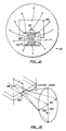
- FIGs. 3A-3C Examples of the focusing pattern on four quadrant detector 34 are shown in Figs. 3A-3C, with the best being shown in Fig. 3B.
- a focus error signal is produced by (A+C)-(B+D).
- Fig. 3A shows the focusing pattern when the beam is out of focus because the medium is too close to the objective lens.
- Fig. 3C shows the focusing pattern when the beam is out of focus due to the medium being too far from the objective lens.
- Fig. 3B shows the focusing pattern (called the circle of least confusion) when the beam is in focus.
- Fig. 3B also shows overlapping beams 40 and 42 which are produced by the grating effect of the grooved structure of medium 18.
- a tracking signal or tracking push-pull signal is given by (A+D)-(B+C). The beam will be on track and the tracking signal will be equal to zero when beams 40 and 42 are of equal brightness.
- One of the disadvantages of the push-pull tracking error signal is that it can be affected by large motion of the objective lens relative to the collimating lens.
- One method to avoid this difficulty is to have the complete optical head follow the motion of the focus and tracking actuator.
- Figs. 1-3 show an optical head using a holographic lens for both beam splitting and focus error detection.
- the focus error and the tracking error are derived from the same four segment detectors.
- this type of optical head is often called a single beam optical head.
- a more popular optical head used in many commercial products is called a three beam optical head which derives the necessary information by focusing three laser beams onto the information medium.
- Fig. 4 shows one embodiment of a prior art three beam optical head 50.
- the optical head consists of a laser pen 52 and a focusing and tracking actuator 54.
- a laser beam 56 is focused on an information medium 58 at a spot 60.
- Laser beam 56 is emitted from a semiconductor laser 62 in the shape of an elliptical cone. It is known to correct some aberrations in the laser beam such as astigmatism by placing a tilted glass cap onto the front surface of the semiconductor laser.
- Laser beam 56 first passes through a grating 64 which diffracts the laser beam into three beams 56, 66, and 67 as shown in Fig. 5.
- each of the laser beams originates from semiconductor laser 62.
- the diffracted beams 66 and 67 appear to originate from virtual laser sources 68 and 69, respectively.
- the angle of separation between each of the diffracted beams and the incident beam is small.
- the beam indicated as 56 is assumed to include the two diffracted beams 66 and 67.
- Beam 56 passes unchanged through a beam splitter 70 to a collimating lens 72.
- the beam is collimated or made substantially parallel by the collimating lens.
- the parallel beam then impinges upon an objective lens 74 which focuses beam 56 onto medium 58 at spot 60.
- the focusing of lens 74 is accomplished through the use of a magnetic coil 76 which moves objective lens 74 up and down with respect to the medium 58.
- a tracking coil may move objective lens 74 horizontally.
- the three beams are reflected off reflective medium 58 through a beam splitter 70. Part of each of the three beams are reflected by the beam-splitter, pass through a cylindrical lens 77 to a six segment photodetector 78.
- Figs. 6A, 6B, and 6C The three beams focused on the medium are shown in Figs. 6A, 6B, and 6C in three different positions 56a, 66a and 67a (corresponding to beams 56, 66 and 67) with respect to a data track 86 between land areas 87.
- Fig. 6A shows center spot 56a, which reads the information from the medium, off to the left of track 86.
- side spot 66a is on data track 86
- side spot 67a is on land area 87.
- the tracks have lower reflectivity than the land areas.
- the beam reflected from side spot 66a has a lower intensity than the beam reflected from side spot 67a.
- center spot 56a is exactly on track.
- Side spots 66a and 67a symmetrically straddle the data track and the land areas.
- the beams reflected from side spots 66a and 67a have the same intensity.
- Fig. 6C shows center spot 56a to the right of the data track. In this case the beam reflected from side spot 66a has greater intensity than the beam reflected from side spot 67a. The difference between the amount of light reflected from the two side spots produces the tracking error signal.
- Fig. 7 shows the three beams imaged at spots 56b, 66b, and 67b on six segment photodetector 78 as described in Fig. 4 above.
- Middle beam 56 of the three beams is imaged at center spot 56b on quadrant detector 95.
- Side beams 66 and 67 are imaged at side spots 66b and 67b on photodetectors 96 and 97, respectively.
- the quadrant detector is used for focusing as described in Figs. 3A-C above.
- photodetectors 96 and 97 are used for tracking by detecting the difference between the intensities of beams 66 and 67 as described with reference to Figs. 6A-6C above. This provides for greater sensitivity of tracking than single beam optical heads.
- the present invention is an improved optical head for reading information recorded on a reflected medium.
- the optical head uses a hologram lens assembly having a transparent plate and a hologram lens, the transparent plate being obliquely positioned relative to a forward and a return beam paths.
- the transparent plate corrects beam aberrations in a laser beam emitted by a semiconductor laser on the forward beam path.
- the hologram lens diffracts the laser beam on the return beam path onto a photodetector. Both the transparent plate and the hologram lens add beam aberrations to the defracted laser beam on the return beam path for tracking purposes.
- the hologram lens assembly may also include a second hologram lens, preferably a three beam diffraction grating, for tracking purposes.
- the hologram lens and the diffraction grating may be located on the obliquely positioned transparent plate or on other transparent plates.
- a semiconductor laser which produces a laser beam which impinges upon a movable objective lens.
- the objective lens focuses the laser beam onto a reflective information medium.
- a transparent plate with a diffraction grating structure recorded on a first surface and a hologram lens recorded on a second surface is placed between the laser and the objective lens.
- the laser beam is diffracted into three dominant beams by the diffraction grating on the first surface. These three beams then pass through the transparent glass plate and the hologram lens on the second surface, thereby correcting beam aberrations such as astigmatism, and further diffracting the three beams into several groups of three beams.
- only the primary group of beams are used in the forward path from laser to the objective lens.
- one of the groups of three beams diffracted by the hologram lens on the second surface bypasses the diffraction grating on the first surface and is focused on an eight segment detector. Furthermore, the hologram lens and the transparent glass plate add aberrations to the beams, thereby providing a means for detecting focus and tracking errors.
- the present invention thus provides a simple one or three beam tracking optical head with less parts than the prior art.
- the present invention is also less susceptible to error due to vibration than the prior art optical heads.
- a holograph lens assembly with a transparent plate, a diffraction grating, and a hologram lens performs the functions of a astigmatic correction lens, a diffraction grating, a beamsplitter, a condensing lens with aberration correction, and a cylindrical lens.
- FIG. 8 A first embodiment of an optical head 100 according to the present invention is shown in Fig. 8.
- the optical head consists of a laser pen 102 and a focusing and tracking actuator 104.
- a laser beam 106 is focused on an information medium 108 at spot 110.
- a semiconductor laser 111 of a semiconductor laser and photodetector assembly 112 radiates laser beam 106 to a holographic lens assembly 113.
- the holographic lens assembly has an oblique transparent plate 114 with a hologram lens, preferably a diffraction grating, on a first surface 114A and a hologram lens on a second surface 114B.
- the beams emerging from the holographic lens assembly collimated by a collimating lens 116 and then focused by objective lens 118 onto medium 108 at spot 110.
- the beams then reflect off medium back through objective lens 118, collimating lens 116, and holographic lens assembly 113.
- the hologram lens on second surface 114B causes diffracted beams to image on photodetector 119.
- Fig. 9 is a side view of holographic plate 114.
- the transparent plate 114 is preferably glass with a hologram lens structure, preferably a grating structure 120, embossed or etched on a first surface 114A and a hologram lens structure 122 embossed or etched on a second surface 114B.
- Grating structure 120 is a diffraction grating with a smaller width than the hologram lens structure 122.
- the thickness of the glass and the separation between the first and second surfaces are selected so that the diffracted beam on the return path will miss grating structure 120. This separation between the first and second surfaces is preferably greater than 3 millimeters.
- the holographic lens assembly can be fabricated by cementing two glass plates together as shown by bond line 124. The holographic lens assembly is preferably placed about 4 millimeters away from the semiconductor laser.
- Fig. 10 is a front view of glass plate first surface 114A showing a preferred structure 120.
- the location of laser beam 106 is shown as a forward laser beam 130 and a return diffracted laser beam 132.
- the return beam bypasses grating structure 120 and is imaged on photodetector 119 shown in Fig. 8.
- Fig. 11 is a front view of glass plate second surface 114B showing a preferred hologram lens structure 122.
- the fringes of the hologram lens structure are either parallel or perpendicular to the fringe direction of the grating structure depending on the orientation of photodetector 119 to holographic lens assembly 113.
- Fig. 12 is a front view of the semiconductor laser and photodetector assembly 113 shown in Fig. 8.
- Semiconductor laser 112 is mounted on a heat sink 142.
- Eight segment photodetector 119 is preferably mounted below the semiconductor laser. The center of the eight segment photodetector is preferably separated from the emitting surface of the semiconductor laser by less than 5 millimeters.
- a rear facet photodetector 146 is mounted behind and preferably tilted with respect to the semiconductor laser.
- the semiconductor laser has a p-n junction parallel to the surface of the heat sink and perpendicular to the surface of the eight segment photodetector.
- Light emitting from a plane parallel to the laser junction 160 ( ⁇ ) comes from a plane on the back surface of the semiconductor laser 162.
- Light emitting from a plane perpendicular to the laser junction 164 ( ⁇ ) comes from a plane on the front surface of the semiconductor laser 166.
- the astigmatic distance (Z) of the semiconductor laser is the distance separating the two planes.
- the grating structure on the first surface of the glass plate diffracts the incident beam into three beams.
- the beams continue to pass through hologram lens structure on the second surface of the glass plate.
- only the zero order diffracted beams from the hologram lens structure are used in the forward path to the information medium. Therefore, it is desirable to reduce the intensity of the remaining beams in order to reduce ambient noise.
- the other diffracted beams from the hologram lens are obstructed by the aperture of collimating lens 116 and the aperture of objective lens 118, thereby diminishing their intensity.
- the holographic lens preferably causes all but the zero order beams to be astigmatic, thereby further decreasing their intensity.
- the three beams focused on the medium have the same appearance as the beams illustrated in Fig. 3.
- the three return beams again pass through the hologram lens producing zero and higher order diffracted beams.
- the zero order beam is astigmatized by the tilted glass plate and diffracted by the grating structure on the first surface and returns to the laser diode. As a result, its intensity is reduced to prevent interference with the operation of the laser diode.
- One of the higher order diffracted beams preferably the first order beam from the hologram lens structure, is astigmatized by the hologram lens structure, the tilted glass plate, and bypassing the grating structure as shown in Fig. 10. The diffracted astigmatized beam is then imaged onto the eight segment photodetector.
- the beams imaged on the eight segment photodetector vary according to the focus and tracking of the beam on the medium. This is illustrated in Fig. 14A-C.
- the middle beam of the three beams is imaged to a quadrant detector 170.
- the two side beams are imaged onto split detectors 172 and 174.
- Fig. 14B shows the beams in its best focus.
- Fig. 14A shows the beams out of focus when the medium is too close to the lens and
- Fig. 14C show the beam out of focus when the medium is too far from the objective lens. This effect is produced by the astigmatism in the beams.
- the focus error signal is produced by (A+C)-(B+D).
- the signal expressing the value of a data point on the information medium is obtained from summing the signals A, B, C, and D.
- Fig. 14B shows also overlapping beams 176, 178, 180 and 182 at the split detectors 172 and 174. These overlapping beams are produced by the diffraction effects of the grooved structure of the information medium.
- the tracking information can be derived from these overlapping beam.
- a tracking error signal can be derived from G-H or E-F.
- a differential method is used to obtain more stable tracking error signals from the pair of split detectors.
- the laser pen shown in Fig. 8 is slightly rotated about an axis extending to the medium so that the phase of the tracking error signal G-H is 180 degrees out of phase with respect to the tracking error signal E-F. That is, when one side beam is centered on a land area, the other side beam will be centered on a track and the middle beam will be bisected.
- the differential tracking error signal according to this present invention is given by (G-H)-(E-F) or alternatively written as (G+F)-(H+E).
- This differential tracking signal eliminates any dc imbalance on the split detectors 172 and 174 caused by the scattered light within the housing of the laser pen. Moreover, it makes the tracking error signal very stable with respect to the movement of the objective lens 118 relative to the collimating lens 116.
- the hologram lens and the grating are recorded on the opposite surfaces of the glass plate.
- multiplexing hologram lens and the regular grating together reduces the amount of light reaching the detector and at the same time introduces spurious images on the photodetector.
- Figs. 15A-15D show alternative holographic lens assemblies 113 where the grating structure 120 and the holographic lens structure 122 are recorded on separated transparent plates 190 and 192. At least one of the transparent plates is oblique with respect to forward beam path 106. The transparent plates are preferably separated by an air gap 194.
- the diffraction grating is oblique with respect to the forward beam or optical axis.
- the diffracted beams from the grating will be distorted by a small amount of astigmatism and coma.
- the holographic assemblies will cause the laser beam to deviate from the optical axis, thereby requiring the optical head to be aligned.
- the optical head can be aligned during assembly by adjusting the position of the semiconductor laser and photodetector assembly.
- the hologram lens and the diffraction grating shown in Fig. 15D are tilted in opposite directions with respect to the forward beam.
- the laser beam is distorted slightly but is not offset from the optical axis.
- the diffraction grating is perpendicular to the optical axis and does not cause distortion of the diffracted beams, but the tilted hologram lens causes the hologram lens to be offset.
- Fig. 16 shows a second embodiment of an optical head according to the present invention in which the collimating lens has been eliminated.
- a semiconductor laser 200 emits a laser beam 202 which passes through a holographic lens assembly 204 and an objective lens 206.
- the laser source is imaged by objective lens 206 onto an information medium 208.
- the reflected beam has one of its first order diffraction beams imaged on a photodetector 210.
- An actuator 212 is used to move objective lens 206 in response to focus and tracking error signals.
- This embodiment represents a trade-off between the modularity of the first embodiment shown in Fig. 8 and the elimination of the collimating lens.
- Fig. 17 shows a third embodiment of an optical head according to the present invention in which a turning mirror is used to reduce the overall height of the optical head.
- a laser diode 300 produces a laser beam 302 which passes through a holographic lens assembly 304, is reflected by a turning mirror 306, and is focused by an objective lens 308 into an information medium 310.
- the reflected beam On the return path, the reflected beam has one of its first order diffraction beams imaged on a photodetector 312.
- An actuator 314 is used to move objective lens 308 in response to focus and tracking error signals.
- This embodiment represents a trade-off between the height of the optical head and the addition of a turning mirror.
- the present invention may be embodied in order specific forms without departing from the spirit or essential characteristics thereof.
- the grating structure could be eliminated from the hologram lens assembly, thereby providing a single beam system.
- other methods such as embossing or photocopying could be used to record the holographic lens structures, including the grating structure, onto a transparent material such as glass, quartz or plastic.
- the eight segment detector can be internally connected to reduce the number of pins used in the laser diode and detector device. Accordingly, the disclosure of the preferred embodiments of the invention is intended to be illustrative, but not limiting, of the scope of the invention which is set forth in the following claims.
Applications Claiming Priority (2)
| Application Number | Priority Date | Filing Date | Title |
|---|---|---|---|
| US362124 | 1989-06-06 | ||
| US07/362,124 US5050153A (en) | 1989-06-06 | 1989-06-06 | Semiconductor laser optical head assembly |
Publications (2)
| Publication Number | Publication Date |
|---|---|
| EP0401764A2 true EP0401764A2 (de) | 1990-12-12 |
| EP0401764A3 EP0401764A3 (de) | 1992-03-04 |
Family
ID=23424787
Family Applications (1)
| Application Number | Title | Priority Date | Filing Date |
|---|---|---|---|
| EP19900110638 Withdrawn EP0401764A3 (de) | 1989-06-06 | 1990-06-05 | Anordnung eines optischen Kopfes mit Halbleiter-Laser |
Country Status (5)
| Country | Link |
|---|---|
| US (1) | US5050153A (de) |
| EP (1) | EP0401764A3 (de) |
| JP (1) | JP2651419B2 (de) |
| KR (1) | KR910001672A (de) |
| CA (1) | CA2018313A1 (de) |
Cited By (7)
| Publication number | Priority date | Publication date | Assignee | Title |
|---|---|---|---|---|
| EP0562488A1 (de) * | 1992-03-19 | 1993-09-29 | Matsushita Electric Industrial Co., Ltd. | Optisches Abtastsystem mit Hyperauflösung |
| EP0669613A1 (de) * | 1994-02-26 | 1995-08-30 | Lg Electronics Inc. | Optisches Abtastsystem |
| EP0749119A2 (de) * | 1995-05-31 | 1996-12-18 | Daewoo Electronics Co., Ltd | Optisches Abtastgerät |
| EP0981063A2 (de) * | 1992-07-14 | 2000-02-23 | Seiko Epson Corporation | Polarisator, OPTISCHES ELEMENT UND OPTISCHER KOPF |
| EP1443505A2 (de) * | 2003-01-29 | 2004-08-04 | Ricoh Company, Ltd. | Optisches Abtastgerät und optisches Plattenlaufwerk |
| EP1484755A2 (de) * | 2003-05-03 | 2004-12-08 | Samsung Electronics Co., Ltd. | Servo-Steuerungsverfahren für einen holografischen Datenspeicher und Apparat der dieses Verfahren verwendet |
| EP2330206A1 (de) | 2003-08-11 | 2011-06-08 | Kweek-en Researchbedrijf Agrico B.V. | Ein Gen aus Solanum bulbocastanum, das gegen Phytophthora infestans resistent macht |
Families Citing this family (29)
| Publication number | Priority date | Publication date | Assignee | Title |
|---|---|---|---|---|
| JP3117211B2 (ja) * | 1990-05-31 | 2000-12-11 | オリンパス光学工業株式会社 | 光学ヘッド |
| US5202875A (en) * | 1991-06-04 | 1993-04-13 | International Business Machines Corporation | Multiple data surface optical data storage system |
| EP0639259B1 (de) * | 1992-05-05 | 1999-07-28 | MicroE, Inc. | Apparat zum detektieren einer relativen bewegung |
| US5486923A (en) * | 1992-05-05 | 1996-01-23 | Microe | Apparatus for detecting relative movement wherein a detecting means is positioned in the region of natural interference |
| DE4301827A1 (de) * | 1993-01-23 | 1994-07-28 | Thomson Brandt Gmbh | Eliminieren von Abtaststörungen |
| US5544143A (en) * | 1994-06-14 | 1996-08-06 | Eastman Kodak Company | Read/write laser-detector-grating unit (LDGU) with an orthogonally-arranged focus and tracking sensor system |
| US5511059A (en) * | 1994-06-14 | 1996-04-23 | Eastman Kodak Company | Multi-element grating beam splitter with a reflection grating element for use in front facet substraction |
| US5565674A (en) * | 1994-09-13 | 1996-10-15 | Eastman Kodak Company | Optical detection and signal conditioning package |
| JPH09259458A (ja) * | 1996-03-22 | 1997-10-03 | Sony Corp | 光学装置及びこの光学装置を用いた光ピックアップ装置 |
| US5710753A (en) * | 1996-06-28 | 1998-01-20 | Eastman Kodak Company | Multi-element grating beam splitter using double refraction to reduce optical feedback and associated light source noise |
| US5696749A (en) * | 1996-06-28 | 1997-12-09 | Eastman Kodak Company | Dual-wavelength optical recording head utilizing grating beam splitter and integrated laser and detectors |
| US5689492A (en) * | 1996-08-06 | 1997-11-18 | Eastman Kodak Company | Assembly used for precisely positioning the component parts of a laser detector grating unit (LDGU) |
| US5710672A (en) * | 1996-09-30 | 1998-01-20 | Eastman Kodak Company | Assembly for positioning the component parts of a laser detector grating unit (LDGU) |
| DE19645150C2 (de) * | 1996-10-28 | 2002-10-24 | Fraunhofer Ges Forschung | Optische Anordnung zur Symmetrierung der Strahlung von Laserdioden |
| US5856961A (en) * | 1997-06-24 | 1999-01-05 | Eastman Kodak Company | Laser detector grating unit (LDGU) for producing focus error, a push-pull tracking error, and differential phase tracking error signals |
| US5991249A (en) * | 1997-07-29 | 1999-11-23 | Hoetron, Inc. | Optical track sensing device |
| JP2002025096A (ja) * | 2000-07-07 | 2002-01-25 | Matsushita Electric Ind Co Ltd | 半導体光源、光ピックアップヘッド装置及び情報記録再生装置 |
| JP2002163830A (ja) * | 2000-11-24 | 2002-06-07 | Toshiba Corp | 光学的収差を利用した光情報処理システムおよび厚みムラのある透明層で保護された記録層を持つ情報媒体 |
| DE10062078A1 (de) * | 2000-12-13 | 2002-06-20 | Thomson Brandt Gmbh | Verfahren zum Erzeugen eines Linsenpositionssignals sowie entsprechendes Gerät zum Lesen und/oder Beschreiben eines optischen Aufzeichnungsträgers |
| US6723980B2 (en) | 2001-07-16 | 2004-04-20 | Wai-Hon Lee | Position sensor with grating to detect moving object with periodic pattern |
| KR100403597B1 (ko) * | 2001-08-30 | 2003-10-30 | 삼성전자주식회사 | 홀로그램이 형성된 빔스프리터를 구비하는 광픽업장치 및이를 이용한 광축보정방법 |
| JP2003163405A (ja) * | 2001-11-26 | 2003-06-06 | Sony Corp | 2波長半導体レーザ素子およびそれに用いられる非点補正板ならびにその配置方法 |
| JP2005025897A (ja) * | 2003-07-04 | 2005-01-27 | Victor Co Of Japan Ltd | 光ピックアップ装置 |
| US8606626B1 (en) | 2007-01-31 | 2013-12-10 | Experian Information Solutions, Inc. | Systems and methods for providing a direct marketing campaign planning environment |
| JP5178107B2 (ja) | 2007-09-14 | 2013-04-10 | オリンパス株式会社 | レーザー走査型顕微鏡 |
| US9057508B1 (en) | 2014-10-22 | 2015-06-16 | Codeshelf | Modular hanging lasers to enable real-time control in a distribution center |
| US9327397B1 (en) | 2015-04-09 | 2016-05-03 | Codeshelf | Telepresence based inventory pick and place operations through robotic arms affixed to each row of a shelf |
| US9262741B1 (en) | 2015-04-28 | 2016-02-16 | Codeshelf | Continuous barcode tape based inventory location tracking |
| US11579014B1 (en) * | 2020-08-20 | 2023-02-14 | Amazon Technologies, Inc. | Optical detector system |
Citations (6)
| Publication number | Priority date | Publication date | Assignee | Title |
|---|---|---|---|---|
| US4458980A (en) * | 1979-09-25 | 1984-07-10 | Sony Corporation | Optical reproducing head |
| EP0241372A1 (de) * | 1986-04-11 | 1987-10-14 | Thomson S.A. | Optische Leseeinrichtung für optische Aufnahmeträger |
| US4776652A (en) * | 1987-10-01 | 1988-10-11 | Camber Corporation | Optical head having two holographic optical elements, with one element inclined relative to the other |
| EP0301643A2 (de) * | 1987-07-29 | 1989-02-01 | Koninklijke Philips Electronics N.V. | Fokussierungsservoschaltung in einem optischen Plattenspieler |
| EP0305169A2 (de) * | 1987-08-24 | 1989-03-01 | Sharp Kabushiki Kaisha | Optische Abtastvorrichtung und optische Gitteranordnung dazu |
| FR2639460A1 (fr) * | 1988-11-21 | 1990-05-25 | Ricoh Kk | Appareil d'enregistrement/reproduction optique |
Family Cites Families (7)
| Publication number | Priority date | Publication date | Assignee | Title |
|---|---|---|---|---|
| JPS53121644A (en) * | 1977-03-31 | 1978-10-24 | Olympus Optical Co Ltd | Detecting method of focal position using holograph |
| JPS5545074A (en) * | 1978-09-28 | 1980-03-29 | Ricoh Co Ltd | Hologram lens |
| JPS61195533U (de) * | 1985-05-29 | 1986-12-05 | ||
| JPS61203427U (de) * | 1985-06-12 | 1986-12-20 | ||
| JPS62139145A (ja) * | 1985-12-11 | 1987-06-22 | Fujitsu Ltd | 光ピツクアツプ |
| US4794585A (en) * | 1986-05-06 | 1988-12-27 | Lee Wai Hon | Optical head having a hologram lens and polarizers for use with magneto-optic medium |
| JPS6455746A (en) * | 1987-08-26 | 1989-03-02 | Sharp Kk | Optical pickup device |
-
1989
- 1989-06-06 US US07/362,124 patent/US5050153A/en not_active Expired - Lifetime
-
1990
- 1990-06-05 CA CA002018313A patent/CA2018313A1/en not_active Abandoned
- 1990-06-05 EP EP19900110638 patent/EP0401764A3/de not_active Withdrawn
- 1990-06-06 JP JP2146414A patent/JP2651419B2/ja not_active Expired - Fee Related
- 1990-06-07 KR KR1019900008357A patent/KR910001672A/ko not_active Application Discontinuation
Patent Citations (6)
| Publication number | Priority date | Publication date | Assignee | Title |
|---|---|---|---|---|
| US4458980A (en) * | 1979-09-25 | 1984-07-10 | Sony Corporation | Optical reproducing head |
| EP0241372A1 (de) * | 1986-04-11 | 1987-10-14 | Thomson S.A. | Optische Leseeinrichtung für optische Aufnahmeträger |
| EP0301643A2 (de) * | 1987-07-29 | 1989-02-01 | Koninklijke Philips Electronics N.V. | Fokussierungsservoschaltung in einem optischen Plattenspieler |
| EP0305169A2 (de) * | 1987-08-24 | 1989-03-01 | Sharp Kabushiki Kaisha | Optische Abtastvorrichtung und optische Gitteranordnung dazu |
| US4776652A (en) * | 1987-10-01 | 1988-10-11 | Camber Corporation | Optical head having two holographic optical elements, with one element inclined relative to the other |
| FR2639460A1 (fr) * | 1988-11-21 | 1990-05-25 | Ricoh Kk | Appareil d'enregistrement/reproduction optique |
Cited By (17)
| Publication number | Priority date | Publication date | Assignee | Title |
|---|---|---|---|---|
| US5978109A (en) * | 1992-03-19 | 1999-11-02 | Matsushita Electric Ind Co Ltd | Superresolution scanning optical device |
| US5496995A (en) * | 1992-03-19 | 1996-03-05 | Matsushita Electric Industrial Co., Ltd. | Superresolution scanning optical device |
| EP0562488A1 (de) * | 1992-03-19 | 1993-09-29 | Matsushita Electric Industrial Co., Ltd. | Optisches Abtastsystem mit Hyperauflösung |
| EP0981063A3 (de) * | 1992-07-14 | 2003-09-17 | Seiko Epson Corporation | Polarisator, OPTISCHES ELEMENT UND OPTISCHER KOPF |
| EP0981063A2 (de) * | 1992-07-14 | 2000-02-23 | Seiko Epson Corporation | Polarisator, OPTISCHES ELEMENT UND OPTISCHER KOPF |
| EP0669613A1 (de) * | 1994-02-26 | 1995-08-30 | Lg Electronics Inc. | Optisches Abtastsystem |
| EP0749119A3 (de) * | 1995-05-31 | 1997-08-20 | Daewoo Electronics Co Ltd | Optisches Abtastgerät |
| US5953294A (en) * | 1995-05-31 | 1999-09-14 | Daewoo Electronics Co., Ltd. | Optical pickup apparatus |
| US5787058A (en) * | 1995-05-31 | 1998-07-28 | Daewoo Electronics Co., Ltd. | Optical pickup apparatus utilizing a polygonal prism |
| EP0749119A2 (de) * | 1995-05-31 | 1996-12-18 | Daewoo Electronics Co., Ltd | Optisches Abtastgerät |
| EP1443505A2 (de) * | 2003-01-29 | 2004-08-04 | Ricoh Company, Ltd. | Optisches Abtastgerät und optisches Plattenlaufwerk |
| EP1443505A3 (de) * | 2003-01-29 | 2007-01-10 | Ricoh Company, Ltd. | Optisches Abtastgerät und optisches Plattenlaufwerk |
| US7359295B2 (en) | 2003-01-29 | 2008-04-15 | Ricoh Company, Ltd. | Optical pickup apparatus and optical disk drive apparatus |
| US8023386B2 (en) | 2003-01-29 | 2011-09-20 | Ricoh Company, Ltd. | Optical pickup apparatus and optical disk drive apparatus |
| EP1484755A2 (de) * | 2003-05-03 | 2004-12-08 | Samsung Electronics Co., Ltd. | Servo-Steuerungsverfahren für einen holografischen Datenspeicher und Apparat der dieses Verfahren verwendet |
| EP1484755A3 (de) * | 2003-05-03 | 2006-10-11 | Samsung Electronics Co., Ltd. | Servo-Steuerungsverfahren für einen holografischen Datenspeicher und Apparat der dieses Verfahren verwendet |
| EP2330206A1 (de) | 2003-08-11 | 2011-06-08 | Kweek-en Researchbedrijf Agrico B.V. | Ein Gen aus Solanum bulbocastanum, das gegen Phytophthora infestans resistent macht |
Also Published As
| Publication number | Publication date |
|---|---|
| CA2018313A1 (en) | 1990-12-06 |
| JPH04117635A (ja) | 1992-04-17 |
| EP0401764A3 (de) | 1992-03-04 |
| KR910001672A (ko) | 1991-01-31 |
| JP2651419B2 (ja) | 1997-09-10 |
| US5050153A (en) | 1991-09-17 |
Similar Documents
| Publication | Publication Date | Title |
|---|---|---|
| US5050153A (en) | Semiconductor laser optical head assembly | |
| US4731772A (en) | Optical head using hologram lens for both beam splitting and focus error detection functions | |
| KR100598645B1 (ko) | 광 기록 매체 | |
| US5696749A (en) | Dual-wavelength optical recording head utilizing grating beam splitter and integrated laser and detectors | |
| US5684762A (en) | Opto-magnetic head apparatus | |
| JP2683918B2 (ja) | 情報面を光学的に走査する装置 | |
| US4924082A (en) | Optical scanning device, mirror objective suitable for use in said device and optical write and/or read apparatus provided with said device | |
| US5293038A (en) | Optical pick-up head apparatus wherein hollographic optical element and photodetector are formed on semiconductor substrate | |
| JP2684822B2 (ja) | 光ピックアップヘッド装置 | |
| EP0463295B1 (de) | Optischer Wiedergabekopf | |
| JPH04341942A (ja) | 光ピックアップ | |
| JP2002109778A (ja) | 光ピックアップ装置 | |
| JP3500158B2 (ja) | 光ヘッド | |
| CA2043387C (en) | Optical head device | |
| US5856961A (en) | Laser detector grating unit (LDGU) for producing focus error, a push-pull tracking error, and differential phase tracking error signals | |
| JP2901728B2 (ja) | 光ヘッド及びそれを用いた情報記録再生装置 | |
| JPH03250437A (ja) | 光情報記録再生装置及び二重回折格子 | |
| JPH085441Y2 (ja) | ビ−ムスプリツタ | |
| JPS63228431A (ja) | 光情報ピツクアツプ装置 | |
| KR0139177B1 (ko) | 초점에러 및 트랙킹에러를 검출하기 위하여 홀로그램을 사용하는 광헤드 | |
| JP2904419B2 (ja) | 光磁気ピックアップ | |
| JP2523469B2 (ja) | 光学記録再生ヘツド | |
| JP2886230B2 (ja) | 光ヘッド及びこれを用いた焦点誤差検出装置 | |
| JP2857245B2 (ja) | 光ピックアップ装置 | |
| JPH06130213A (ja) | 光ピックアップ装置 |
Legal Events
| Date | Code | Title | Description |
|---|---|---|---|
| PUAI | Public reference made under article 153(3) epc to a published international application that has entered the european phase |
Free format text: ORIGINAL CODE: 0009012 |
|
| AK | Designated contracting states |
Kind code of ref document: A2 Designated state(s): DE FR GB IT NL |
|
| PUAL | Search report despatched |
Free format text: ORIGINAL CODE: 0009013 |
|
| AK | Designated contracting states |
Kind code of ref document: A3 Designated state(s): DE FR GB IT NL |
|
| STAA | Information on the status of an ep patent application or granted ep patent |
Free format text: STATUS: THE APPLICATION IS DEEMED TO BE WITHDRAWN |
|
| 18D | Application deemed to be withdrawn |
Effective date: 19920907 |