EP0241372A1 - Optische Leseeinrichtung für optische Aufnahmeträger - Google Patents
Optische Leseeinrichtung für optische Aufnahmeträger Download PDFInfo
- Publication number
- EP0241372A1 EP0241372A1 EP87400773A EP87400773A EP0241372A1 EP 0241372 A1 EP0241372 A1 EP 0241372A1 EP 87400773 A EP87400773 A EP 87400773A EP 87400773 A EP87400773 A EP 87400773A EP 0241372 A1 EP0241372 A1 EP 0241372A1
- Authority
- EP
- European Patent Office
- Prior art keywords
- reading device
- optical reading
- recording medium
- grooves
- optical
- Prior art date
- Legal status (The legal status is an assumption and is not a legal conclusion. Google has not performed a legal analysis and makes no representation as to the accuracy of the status listed.)
- Granted
Links
- 230000003287 optical effect Effects 0.000 claims abstract description 60
- 230000010287 polarization Effects 0.000 claims abstract description 31
- 238000001514 detection method Methods 0.000 claims abstract description 29
- 239000000463 material Substances 0.000 claims abstract description 14
- 201000009310 astigmatism Diseases 0.000 claims description 11
- 239000004973 liquid crystal related substance Substances 0.000 claims description 8
- 229920000642 polymer Polymers 0.000 claims description 8
- 239000011521 glass Substances 0.000 claims description 7
- 230000000694 effects Effects 0.000 claims description 4
- 239000003507 refrigerant Substances 0.000 claims description 3
- 238000001816 cooling Methods 0.000 claims description 2
- 230000001939 inductive effect Effects 0.000 claims description 2
- 239000002861 polymer material Substances 0.000 claims 3
- 239000004988 Nematic liquid crystal Substances 0.000 claims 1
- 230000005540 biological transmission Effects 0.000 description 3
- 230000010363 phase shift Effects 0.000 description 3
- 238000005530 etching Methods 0.000 description 2
- 229910052710 silicon Inorganic materials 0.000 description 2
- 239000010703 silicon Substances 0.000 description 2
- 210000002858 crystal cell Anatomy 0.000 description 1
- 230000009977 dual effect Effects 0.000 description 1
- 239000000374 eutectic mixture Substances 0.000 description 1
- 230000001747 exhibiting effect Effects 0.000 description 1
- 230000014509 gene expression Effects 0.000 description 1
- 230000010354 integration Effects 0.000 description 1
- 238000012986 modification Methods 0.000 description 1
- 230000004048 modification Effects 0.000 description 1
- 238000001259 photo etching Methods 0.000 description 1
- 230000001105 regulatory effect Effects 0.000 description 1
- 239000000126 substance Substances 0.000 description 1
Images


Classifications
-
- G—PHYSICS
- G11—INFORMATION STORAGE
- G11B—INFORMATION STORAGE BASED ON RELATIVE MOVEMENT BETWEEN RECORD CARRIER AND TRANSDUCER
- G11B7/00—Recording or reproducing by optical means, e.g. recording using a thermal beam of optical radiation by modifying optical properties or the physical structure, reproducing using an optical beam at lower power by sensing optical properties; Record carriers therefor
- G11B7/12—Heads, e.g. forming of the optical beam spot or modulation of the optical beam
- G11B7/135—Means for guiding the beam from the source to the record carrier or from the record carrier to the detector
- G11B7/1365—Separate or integrated refractive elements, e.g. wave plates
-
- G—PHYSICS
- G02—OPTICS
- G02B—OPTICAL ELEMENTS, SYSTEMS OR APPARATUS
- G02B5/00—Optical elements other than lenses
- G02B5/18—Diffraction gratings
- G02B5/1833—Diffraction gratings comprising birefringent materials
-
- G—PHYSICS
- G02—OPTICS
- G02B—OPTICAL ELEMENTS, SYSTEMS OR APPARATUS
- G02B27/00—Optical systems or apparatus not provided for by any of the groups G02B1/00 - G02B26/00, G02B30/00
- G02B27/28—Optical systems or apparatus not provided for by any of the groups G02B1/00 - G02B26/00, G02B30/00 for polarising
- G02B27/283—Optical systems or apparatus not provided for by any of the groups G02B1/00 - G02B26/00, G02B30/00 for polarising used for beam splitting or combining
-
- G—PHYSICS
- G02—OPTICS
- G02B—OPTICAL ELEMENTS, SYSTEMS OR APPARATUS
- G02B5/00—Optical elements other than lenses
- G02B5/30—Polarising elements
- G02B5/3083—Birefringent or phase retarding elements
-
- G—PHYSICS
- G11—INFORMATION STORAGE
- G11B—INFORMATION STORAGE BASED ON RELATIVE MOVEMENT BETWEEN RECORD CARRIER AND TRANSDUCER
- G11B7/00—Recording or reproducing by optical means, e.g. recording using a thermal beam of optical radiation by modifying optical properties or the physical structure, reproducing using an optical beam at lower power by sensing optical properties; Record carriers therefor
- G11B7/08—Disposition or mounting of heads or light sources relatively to record carriers
- G11B7/09—Disposition or mounting of heads or light sources relatively to record carriers with provision for moving the light beam or focus plane for the purpose of maintaining alignment of the light beam relative to the record carrier during transducing operation, e.g. to compensate for surface irregularities of the latter or for track following
- G11B7/0908—Disposition or mounting of heads or light sources relatively to record carriers with provision for moving the light beam or focus plane for the purpose of maintaining alignment of the light beam relative to the record carrier during transducing operation, e.g. to compensate for surface irregularities of the latter or for track following for focusing only
- G11B7/0909—Disposition or mounting of heads or light sources relatively to record carriers with provision for moving the light beam or focus plane for the purpose of maintaining alignment of the light beam relative to the record carrier during transducing operation, e.g. to compensate for surface irregularities of the latter or for track following for focusing only by astigmatic methods
-
- G—PHYSICS
- G11—INFORMATION STORAGE
- G11B—INFORMATION STORAGE BASED ON RELATIVE MOVEMENT BETWEEN RECORD CARRIER AND TRANSDUCER
- G11B7/00—Recording or reproducing by optical means, e.g. recording using a thermal beam of optical radiation by modifying optical properties or the physical structure, reproducing using an optical beam at lower power by sensing optical properties; Record carriers therefor
- G11B7/12—Heads, e.g. forming of the optical beam spot or modulation of the optical beam
- G11B7/123—Integrated head arrangements, e.g. with source and detectors mounted on the same substrate
-
- G—PHYSICS
- G11—INFORMATION STORAGE
- G11B—INFORMATION STORAGE BASED ON RELATIVE MOVEMENT BETWEEN RECORD CARRIER AND TRANSDUCER
- G11B7/00—Recording or reproducing by optical means, e.g. recording using a thermal beam of optical radiation by modifying optical properties or the physical structure, reproducing using an optical beam at lower power by sensing optical properties; Record carriers therefor
- G11B7/12—Heads, e.g. forming of the optical beam spot or modulation of the optical beam
- G11B7/135—Means for guiding the beam from the source to the record carrier or from the record carrier to the detector
- G11B7/1353—Diffractive elements, e.g. holograms or gratings
-
- G—PHYSICS
- G11—INFORMATION STORAGE
- G11B—INFORMATION STORAGE BASED ON RELATIVE MOVEMENT BETWEEN RECORD CARRIER AND TRANSDUCER
- G11B7/00—Recording or reproducing by optical means, e.g. recording using a thermal beam of optical radiation by modifying optical properties or the physical structure, reproducing using an optical beam at lower power by sensing optical properties; Record carriers therefor
- G11B7/12—Heads, e.g. forming of the optical beam spot or modulation of the optical beam
- G11B7/135—Means for guiding the beam from the source to the record carrier or from the record carrier to the detector
- G11B7/1381—Non-lens elements for altering the properties of the beam, e.g. knife edges, slits, filters or stops
Definitions
- the invention relates to an optical reading device for an optical recording medium applicable in particular to optical heads for reading optical discs designated commercially by expressions such as compact discs, video discs or digital optical discs.
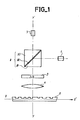
- a known type optical disc reading device comprises at least, as shown in FIG. 1: - a laser source emitting a linearly polarized light beam 1; - a polarization separator element 8; - a quarter wave plate 3; - a focus objective 4; - a set of signal detectors and positioning errors 9.
- the polarization separator element is a glass cube comprising in its median plane a superposition of thin dielectric layers 82 ensuring the reflection of a tangentially polarized wave and the transmission of a sagittally polarized wave.
- the laser source 1 emits a light beam whose polarization is such that the beam is reflected, by the polarization splitter, towards the quarter-wave plate 3.
- the beam is then transformed into a beam with circular polarization and is focused by the lens 4 on disk 5.
- the beam is reflected with a phase shift.
- the quarter-wave plate 3 then transforms the circularly polarized beam into a linearly polarized beam.
- the beam obtained is retransmitted by the separator cube 8 to the set of detectors 9 which can be, in FIG. 1, a photodetector.
- the amount of light detected by the photodetector depends on the importance of phase shift introduced by the disc 5 and therefore the amount of light retransmitted by the separator cube 8.
- the invention makes it possible to overcome these three types of drawbacks by proposing an inexpensive, space-saving optical reading device, the design of which does not involve mounting and positioning constraints of the elements with respect to each other.
- an optical reading device for an optical recording medium comprising: - a laser source emitting along a determined axis, a first linearly polarized beam and of determined wavelength; - a beam splitter receiving the first beam and retransmitting it in the form of a second beam; - a focusing lens which focuses this second beam in the form of a fourth reading beam; a recording medium receiving the fourth reading beam and reflecting it in the form of a fifth beam towards the focusing lens, and the beam splitter which retransmits at least one detection beam; - at least one fe detection device receiving the detection beam and providing at least one electrical signal translating the detection carried out; - characterized in that the beam splitter comprises a phase network comprising means inducing an astigmatism effect on the detection beam.
- optical recording medium comprising: - a laser source emitting along a determined axis, a first linearly polarized beam and of determined wavelength; - a polarization beam splitter receiving the first beam and retransmitting it in the form of a second beam to a quarter-wave plate which transmits in exchange a third beam with circular polarization; - a focusing lens which focuses this third beam in the form of a fourth reading beam; a recording medium receiving the fourth reading beam and reflecting it in the form of a fifth beam towards the focusing lens, the quarter-wave plate and the beam splitter by polarization which retransmits at least one detection beam ; - at least one detection device receiving the detection beam and supplying at least one electrical signal translating the detection carried out; - characterized in that the polarization beam splitter comprises a phase grating comprised between a first medium and a second medium, at least one of which is birefringent, the indices of the two mediums being equal
- Figure 1 relates to an optical read head according to the known art as described above. It appears that the position of the laser source 1 and its orientation with respect to the beam splitter device 8, represented in the form of a separator cube are difficult to adjust. Likewise, the position of the photodetector 9 relative to the beam reflected by the disc 5 and therefore relative to the assembly constituted by the laser source 1, the separating cube 8 and the disc 5, must be precise. It follows that the position adjustments being made, they should no longer be susceptible to modifications due for example to reasons of thermal expansion. The housing, not shown in the figure, which contains the various elements of Figure 1, must therefore be made of material which can be machined with great precision and exhibiting almost no expansion or deformation under the effect of the temperature variation. . This is why the device in the figure leads to a relatively expensive optical disc read head.
- the different elements of the optical reading device shown in FIG. 2 are aligned along the same axis YY ⁇ perpendicular to the plane of the recording medium or optical disc 5.
- FIG. 2 the optical reading device and the disc 5 have been shown in section.
- the disc information moves along an axis XX ⁇ .
- the axis YY ⁇ of the optical reading device is perpendicular to the axis XX ⁇ .
- the reading device includes: a light source such as a laser source 1 placed on the axis YY ⁇ and emitting, along this axis YY ⁇ a beam F1 of linearly polarized light; - A polarization beam splitter 2 comprising a phase grating located at the interface of two media, one of which is not birefringent and the other is birefringent. This beam splitter is placed perpendicular to the beam F1. It retransmits an F2 beam and does not affect the transmission due to the type and direction of polarization of the light.
- a light source such as a laser source 1 placed on the axis YY ⁇ and emitting, along this axis YY ⁇ a beam F1 of linearly polarized light
- a polarization beam splitter 2 comprising a phase grating located at the interface of two media, one of which is not birefringent and the other is birefringent. This beam splitter is placed perpendicular to the beam F1. It
- the beam after reflection by the optical disc may be subject to refraction; a quarter-wave plate 3 receiving the beam F2 with linear polarization and retransmitting a beam F3 with circular polarization; - A lens 4 focusing the beam F3 in the form of a beam F4 so as to project a read beam on the optical disc 5; - The optical disc 5, the information such as 50 of which is movable along the axis XX ⁇ and passes successively under the reading beam F4; - Detection devices 6 and 7 located in a plane P ⁇ not conjugate with the plane of the disc, near the laser source 1, on either side of the axis YY ⁇ , aligned in a direction parallel to the axis XX ⁇ that is to say parallel to the direction of movement of the information on the disk 5.
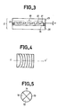
- the beam splitter 2 is produced, for example, as shown in FIG. 3.
- a transparent blade 23 made of glass for example, provided with a network 20 of grooves such as 21 and 22.
- a blade 25 also transparent, made of glass for example, determining with the blade 23 a space which is filled with a birefringent material 24 such that 'a liquid crystal.
- a seal 26 holds the liquid crystal between the two blades.
- the index of refraction of the medium constituting the plate 23 being n o , the birefringent material 24 is chosen in such a way that for the polarization of the beam F2 which it receives, its refractive index is also n o .
- the index n o of the medium constituting the plate 23 and the index n e constituting the birefringent medium are different.
- liquid crystal a eutectic mixture such as that known under the trade name E7 and manufactured by the company BDH Chemicals Ltd (United Kingdom).
- refractive index n e of birefringence is approximately 1.725. Let be an index difference between the two media 23 and 24 of 0.225.
- the depth e of the grooves 21.22 of the network 20 must be chosen equal to 1.77 ⁇ m.
- the pitch of the grooves is typically equal to 10 ⁇ m.
- the orientation of the molecules parallel to the glass slides is obtained by a conventional treatment of the rubbed polymer type.
- the liquid crystal can be replaced by any other birefringent material (e.g. oriented polymer, or polymer having a liquid crystal phase at high temperature).
- oriented polymer or polymer having a liquid crystal phase at high temperature.
- the orientation of the polymer chains, parallel to the etchings, would be obtained by passing through the nematic phase at high temperature, this orientation being preserved during cooling in the polymer phase.
- the photodetectors 6 and 7 are integrated on the same assembly or chip 16 preferably made of silicon.
- This silicon chip 16 may include a central detector not shown in the figure for regulating the power emitted by the laser source.
- the role of photodetectors 6 and 7 is to detect errors in radial and vertical positioning and to read the signal carried by the disc.
- the chip 16 and the source 1 can be assembled in the same case and pre-positioned with respect to each other.
- the lens 4 can be moved separately or integrally from the rest of the assembly to follow the radial and vertical errors.
- the laser source 1 and the elements of the chip 16 such as the photodetectors 6 and 7 are connected by electrical connections 11, 12, 13, 14 to external circuits not shown.
- the operation of the optical reading device thus described is such that a reading beam F4 is reflected by the disc 5 in the form of a beam F5.
- the beam F5 gives rise after transmission by the lens 4, the quarter-wave plate 3 and the separator 2, to two diffracted beams F8 and F8 ⁇ symmetrical with respect to the axis YY ⁇ and of the same intensity.
- These beams reach the chip 16 at the location of the detectors 6 and 7 which detect a certain amount of light.
- the beam F4 reaches the disk 5 at the location of an information signal, the beam undergoes a phase shift of its polarization. This results in a different diffraction by the polarization splitter 2. Part of the light from the beams F8 and F8 ⁇ does not reach the photodetectors 6 and 7. These then detect less light.
- the grooves 21 and 22 of the network 20 are rectilinear and parallel.
- the network then has a configuration as shown in FIG. 4 with portions of concentric ellipses, one of the axes of which is UU ⁇ .
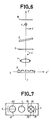
- one of the photodetectors, 7 for example, comprises four photodetectors 70, 71, 72, 73 arranged in a cross in the plane P ⁇ as shown in FIG. 5.
- the diffracted beam F8 ⁇ reaches the photodetectors 70, 71, 72 and 73 in the form of a circle and illuminates each detector equivalently.
- the beam F8 ⁇ projects on the photodetectors 70 to 73 an image of elliptical shape whose l 'one of the axes will be parallel to the axis UU ⁇ .
- the major axis of the elliptical image on the phtodetectors 70 to 73 will be parallel to the axis UU ⁇ and two phtodetectors, 70 and 72 for example, would receive more light than the other two phtodetectors 71 and 73.
- the major axis of the image on the photodetectors will be perpendicular to the axis UU ⁇ and these are the two photodetectors 71 and 73 which will receive more light than photodetectors 70 and 72.
- the astigmatism of the network 20 can be increased by tilting the separator 2 relative to the axis YY ⁇ .
- the separator 2 is then inclined relative to the axis YY ⁇ to give the network 20 of circular shape an effect of astigmatism.
- the photodetector 6 can also include several photodetectors. In particular, it may include two photodetectors 60, 61 aligned in a direction orthogonal to the direction of travel of the information from the disc (axis XX ⁇ ).
- These photodetectors 60 and 61 are placed in such a way that, when the beam F4 is centered relative to a track of the disc 5, they both receive the same amount of light.
- the photodetectors 60 and 61 then operate in a mode called push-pull and serve to radially slave the axis YY Y of the reading device with respect to an information track of the disc 5.
- photodetectors 70 to 73 making it possible to adjust the focus of the reading beam on the disc 5, and photodetectors 60, 61 allowing a radial control of the reading beam on the disc, gives an assembly represented, in FIG. 7, in view from below.
- FIG. 7 there are on either side of the laser source 1, the four photodetectors 70 to 73 arranged in a cross and the two photodetectors 60 and 61 joined to one another.
- the beam splitter is a polarization beam splitter and in particular a separator comprising a birefringent medium.
- the system thus described also works with a beam splitter 2 which does not have a birefringent medium.
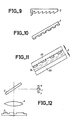
- FIG. 8 represents such an embodiment of the device of the invention.
- the beam splitter 2 consists of a transparent blade whose index of refraction (n) is different from that of the medium located on either side of the separator 2.
- the separator 2 comprises a network of grooves.
- the device of FIG. 8 does not include a quarter-wave plate. However, although this is not shown, it is possible to provide one between the separator 2 and the lens 4 for example. This quarter-wave plate will then possibly reduce the noise on the laser by avoiding sending back to the laser light of the same polarization.
- the grooves of the network of the separator 2 are, according to an exemplary embodiment, parallel rectilinear grooves.
- They can also be concentric circular grooves.
- the separator 2 is inclined relative to the axis YY ⁇ of the device as shown in figure 6.
- the separator can then have rectilinear grooves and it is inclined against the direction of diffraction to increase astigmatism. It can also have concentric circular grooves which already introduce an astigmatism, but by tilting the separator, one accentuates the astigmatism.
- the furrows can also be elliptical and the network then introduces an astigmatism like an inclined network of circular furrows.
- the grooves may also have a triangular cross section. More precisely, they can also have sawtooth shapes (blazed grating in English terminology) such as that represented in FIG. 2.
- the depth e of each tooth then has a value such that we have: e. ⁇ n ⁇ ⁇ ⁇ n being the difference in refractive indices of the separator 2 and of the medium located on either side ⁇ being the light wavelength.
- the network of grooves in the separator 2 can be reflective, for example metallized.
- FIG. 12 then represents the position of the separator in the detection device with respect to the laser source 1 and the detectors 6, 7 on the one hand, and with respect to the recording medium 5 on the other hand.
- the separator 2 then works in reflection and refraction and the operation is similar to that described above.
- optical reading device thus described can be made compactly with reduced dimensions compared to known devices.
Landscapes
- Physics & Mathematics (AREA)
- Optics & Photonics (AREA)
- General Physics & Mathematics (AREA)
- Optical Head (AREA)
- Optical Recording Or Reproduction (AREA)
- Facsimile Scanning Arrangements (AREA)
- Optical Communication System (AREA)
- Holo Graphy (AREA)
- Mechanical Optical Scanning Systems (AREA)
- Supporting Of Heads In Record-Carrier Devices (AREA)
- Laser Beam Printer (AREA)
Priority Applications (1)
| Application Number | Priority Date | Filing Date | Title |
|---|---|---|---|
| AT87400773T ATE66762T1 (de) | 1986-04-11 | 1987-04-07 | Optische leseeinrichtung fuer optische aufnahmetraeger. |
Applications Claiming Priority (2)
| Application Number | Priority Date | Filing Date | Title |
|---|---|---|---|
| FR8605239 | 1986-04-11 | ||
| FR8605239A FR2597249B1 (fr) | 1986-04-11 | 1986-04-11 | Dispositif de lecture optique de support d'enregistrement optique |
Publications (2)
| Publication Number | Publication Date |
|---|---|
| EP0241372A1 true EP0241372A1 (de) | 1987-10-14 |
| EP0241372B1 EP0241372B1 (de) | 1991-08-28 |
Family
ID=9334165
Family Applications (1)
| Application Number | Title | Priority Date | Filing Date |
|---|---|---|---|
| EP87400773A Expired - Lifetime EP0241372B1 (de) | 1986-04-11 | 1987-04-07 | Optische Leseeinrichtung für optische Aufnahmeträger |
Country Status (11)
| Country | Link |
|---|---|
| US (1) | US5168485A (de) |
| EP (1) | EP0241372B1 (de) |
| JP (3) | JP2589337B2 (de) |
| KR (1) | KR100235125B1 (de) |
| AT (1) | ATE66762T1 (de) |
| AU (1) | AU7167587A (de) |
| CA (1) | CA1301319C (de) |
| DE (1) | DE3772426D1 (de) |
| ES (1) | ES2024528B3 (de) |
| FR (1) | FR2597249B1 (de) |
| WO (1) | WO1987006386A1 (de) |
Cited By (8)
| Publication number | Priority date | Publication date | Assignee | Title |
|---|---|---|---|---|
| EP0244827A3 (en) * | 1986-05-06 | 1989-01-18 | Wai-Hon Lee | Improved optical head |
| FR2646245A1 (fr) * | 1989-04-25 | 1990-10-26 | Thomson Csf | Dispositif de lecture optique pour support d'enregistrement optique |
| EP0390445A3 (de) * | 1989-03-27 | 1992-01-22 | Matsushita Electric Industrial Co., Ltd. | Optischer Abtastkopf |
| GB2247099A (en) * | 1990-07-09 | 1992-02-19 | Asahi Optical Co Ltd | Optical system using polarized light. |
| EP0401764A3 (de) * | 1989-06-06 | 1992-03-04 | Pencom International Corporation | Anordnung eines optischen Kopfes mit Halbleiter-Laser |
| EP0390610A3 (de) * | 1989-03-31 | 1992-09-16 | Sharp Kabushiki Kaisha | Optisches Element und dieses enthaltende optische Abtasteinrichtung |
| US5210627A (en) * | 1990-05-31 | 1993-05-11 | Mitsubishi Denki Kabushiki Kaisha | Optical record and reproduction apparatus with liquid crystal panel that rotates light followed by a polarizer or birefringent plate |
| EP0612064A3 (de) * | 1988-06-23 | 1995-08-30 | Sharp Kk | Optische Abtastvorrichtung. |
Families Citing this family (22)
| Publication number | Priority date | Publication date | Assignee | Title |
|---|---|---|---|---|
| NL8502835A (nl) * | 1985-10-17 | 1987-05-18 | Philips Nv | Inrichting voor het met optische straling aftasten van een informatievlak. |
| EP0405444B1 (de) * | 1989-06-26 | 1997-09-03 | Nec Corporation | Optisches System |
| JP2616018B2 (ja) * | 1989-06-26 | 1997-06-04 | 日本電気株式会社 | 光ヘッド装置 |
| US5581523A (en) * | 1992-11-17 | 1996-12-03 | Seiko Epson Corporation | Laser emission unit, optical head and optical memory device |
| JP3362896B2 (ja) * | 1993-01-25 | 2003-01-07 | ソニー株式会社 | 光ピックアップ及び光ディスク装置 |
| US5757754A (en) * | 1994-06-30 | 1998-05-26 | Matsushita Electric Industrial Co., Ltd. | Holographic optical head |
| FR2723243B1 (fr) * | 1994-07-26 | 1996-09-06 | Thomson Csf | Dispositif d'enregistrement et/ou de lecture de tetes magnetiques et son procede de realisation |
| US6026065A (en) * | 1995-03-04 | 2000-02-15 | Lg Electronics Inc. | Optical pick-up apparatus capable of reading data irrespective of disc type |
| WO1997013245A1 (fr) | 1995-10-03 | 1997-04-10 | Asahi Glass Company Ltd. | Dispositif tete optique et procede de fabrication associe |
| US6618116B1 (en) | 1997-10-02 | 2003-09-09 | Asahi Glass Company, Limited | Optical head device and a diffraction element suitable for the device, and a method of manufacturing the diffraction element and the optical head device |
| FR2786345B1 (fr) | 1998-11-24 | 2001-02-09 | Thomson Csf | Dispositif de cryptage quantique |
| US6584059B1 (en) * | 1999-02-17 | 2003-06-24 | Matsushita Electric Industrial Co., Ltd. | Information recording and reproducing apparatus |
| US7149173B2 (en) * | 2000-10-17 | 2006-12-12 | Thales | Medium for recording optically readable data, method for making same and optical system reproducing said data |
| JP2002250809A (ja) * | 2001-02-26 | 2002-09-06 | Alps Electric Co Ltd | 光学部材およびそれを用いた光ピックアップ |
| FR2824905B1 (fr) * | 2001-05-15 | 2003-08-29 | Thomson Csf | Gyrometre a fibre optique |
| FR2837972B1 (fr) | 2002-04-02 | 2006-07-21 | Thales Sa | Procede d'asservissement radial pour un dispositif de reproduction d'informations d'un disque optique et dispositif de reproduction mettant en oeuvre ce procede |
| JP4106981B2 (ja) * | 2002-06-28 | 2008-06-25 | 旭硝子株式会社 | 光減衰器 |
| CN1774750A (zh) * | 2003-04-14 | 2006-05-17 | 皇家飞利浦电子股份有限公司 | 光学扫描设备 |
| US9938844B2 (en) | 2011-10-26 | 2018-04-10 | General Electric Company | Metallic stator seal |
| US10161523B2 (en) | 2011-12-23 | 2018-12-25 | General Electric Company | Enhanced cloth seal |
| US9551569B2 (en) * | 2014-10-13 | 2017-01-24 | Hermes-Epitek Corporation | Apparatus and method for curvature and thin film stress measurement |
| US11269193B2 (en) * | 2017-11-27 | 2022-03-08 | Liqxtal Technology Inc. | Optical sensing device and structured light projector |
Citations (5)
| Publication number | Priority date | Publication date | Assignee | Title |
|---|---|---|---|---|
| GB2059057A (en) * | 1979-09-28 | 1981-04-15 | Philips Nv | Photo-electric focussing error detection |
| FR2538580A1 (fr) * | 1982-12-25 | 1984-06-29 | Pioneer Electronic Corp | Dispositif de lecture optique |
| EP0147749A2 (de) * | 1983-12-16 | 1985-07-10 | Hitachi, Ltd. | Optischer Kopf |
| DE3522849A1 (de) * | 1984-06-27 | 1986-01-02 | Canon Denshi K.K., Chichibu, Saitama | Optischer kopf |
| EP0219908A1 (de) * | 1985-10-17 | 1987-04-29 | Koninklijke Philips Electronics N.V. | Gerät zur optischen Abtastung einer Informationsebene |
Family Cites Families (13)
| Publication number | Priority date | Publication date | Assignee | Title |
|---|---|---|---|---|
| JPS51100628A (de) * | 1975-03-03 | 1976-09-06 | Hitachi Ltd | |
| JPS6213Y2 (de) * | 1981-03-20 | 1987-01-06 | ||
| JPS58130148A (ja) * | 1982-01-28 | 1983-08-03 | 三重県 | 額縁等の立体的装飾成形体用成形材料ならびにそれを用いた成形方法 |
| JPH069089B2 (ja) * | 1985-04-05 | 1994-02-02 | 日本電気株式会社 | 光ヘツド |
| JPS61178740A (ja) * | 1985-02-05 | 1986-08-11 | Canon Inc | 光ヘツド装置 |
| CA1257392A (en) * | 1985-03-20 | 1989-07-11 | Masayuki Kato | Optical pickup with hologram lenses |
| JPS6226654A (ja) * | 1985-07-26 | 1987-02-04 | Nec Corp | 光ヘツド |
| JPS62139146A (ja) * | 1985-12-12 | 1987-06-22 | Nec Corp | 光ヘツド装置 |
| DE3679648D1 (de) * | 1985-12-10 | 1991-07-11 | Nec Corp | Optischer kopf mit einem beugungsgitter zum richten von zwei oder mehreren gebeugten lichtstrahlen auf optische detektoren. |
| JPH0630164B2 (ja) * | 1985-12-16 | 1994-04-20 | キヤノン株式会社 | 光ヘツド装置 |
| NL8601974A (nl) * | 1986-08-01 | 1988-03-01 | Philips Nv | Inrichting voor het met optische straling aftasten van een stralingsreflekterend informatievlak. |
| JPH0514334Y2 (de) * | 1986-10-01 | 1993-04-16 | ||
| JPH0777038B2 (ja) * | 1986-12-25 | 1995-08-16 | ソニー株式会社 | 光学ピツクアツプ装置 |
-
1986
- 1986-04-11 FR FR8605239A patent/FR2597249B1/fr not_active Expired
-
1987
- 1987-03-31 AU AU71675/87A patent/AU7167587A/en not_active Abandoned
- 1987-03-31 WO PCT/FR1987/000102 patent/WO1987006386A1/fr not_active Ceased
- 1987-03-31 JP JP62502219A patent/JP2589337B2/ja not_active Expired - Lifetime
- 1987-03-31 KR KR1019870701164A patent/KR100235125B1/ko not_active Expired - Lifetime
- 1987-04-07 ES ES87400773T patent/ES2024528B3/es not_active Expired - Lifetime
- 1987-04-07 EP EP87400773A patent/EP0241372B1/de not_active Expired - Lifetime
- 1987-04-07 DE DE8787400773T patent/DE3772426D1/de not_active Expired - Lifetime
- 1987-04-07 AT AT87400773T patent/ATE66762T1/de active
- 1987-04-09 CA CA000534212A patent/CA1301319C/fr not_active Expired - Lifetime
-
1991
- 1991-07-17 US US07/731,428 patent/US5168485A/en not_active Expired - Lifetime
-
1996
- 1996-07-08 JP JP8178194A patent/JP2935418B2/ja not_active Expired - Lifetime
-
1998
- 1998-01-08 JP JP10002532A patent/JPH10188336A/ja active Pending
Patent Citations (5)
| Publication number | Priority date | Publication date | Assignee | Title |
|---|---|---|---|---|
| GB2059057A (en) * | 1979-09-28 | 1981-04-15 | Philips Nv | Photo-electric focussing error detection |
| FR2538580A1 (fr) * | 1982-12-25 | 1984-06-29 | Pioneer Electronic Corp | Dispositif de lecture optique |
| EP0147749A2 (de) * | 1983-12-16 | 1985-07-10 | Hitachi, Ltd. | Optischer Kopf |
| DE3522849A1 (de) * | 1984-06-27 | 1986-01-02 | Canon Denshi K.K., Chichibu, Saitama | Optischer kopf |
| EP0219908A1 (de) * | 1985-10-17 | 1987-04-29 | Koninklijke Philips Electronics N.V. | Gerät zur optischen Abtastung einer Informationsebene |
Non-Patent Citations (3)
| Title |
|---|
| IBM TECHNICAL DISCLOSURE BULLETIN, vol. 22, no. 4, septembre 1979, page 1646, New York, US; M.R. LATTA et al.: "Multi-fonction holographic optical element for readout of high density recorded data" * |
| PATENT ABSTRACTS OF JAPAN, vol. 7, no. 245 (P-233)[1390], 29 octobre 1983; & JP-A-58 130 448 (TOKYO SHIBAURA DENKI K.K.) 03-08-1983 * |
| PATENT ABSTRACTS OF JAPAN, vol. 9, no. 37 (P-335)[1760], 16 février 1985; & JP-A-59 177 734 (TOSHIBA K.K.) 08-10-1984 * |
Cited By (13)
| Publication number | Priority date | Publication date | Assignee | Title |
|---|---|---|---|---|
| EP0244827A3 (en) * | 1986-05-06 | 1989-01-18 | Wai-Hon Lee | Improved optical head |
| EP0612064A3 (de) * | 1988-06-23 | 1995-08-30 | Sharp Kk | Optische Abtastvorrichtung. |
| EP0390445A3 (de) * | 1989-03-27 | 1992-01-22 | Matsushita Electric Industrial Co., Ltd. | Optischer Abtastkopf |
| EP0390610A3 (de) * | 1989-03-31 | 1992-09-16 | Sharp Kabushiki Kaisha | Optisches Element und dieses enthaltende optische Abtasteinrichtung |
| EP0803868A3 (de) * | 1989-03-31 | 1997-11-12 | Sharp Kabushiki Kaisha | Optischer Bauteil und optisches Wiedergabegerät mit dergleichem |
| WO1990013117A1 (fr) * | 1989-04-25 | 1990-11-01 | Thomson-Csf | Dispositif de lecture optique pour support d'enregistrement optique |
| US5172368A (en) * | 1989-04-25 | 1992-12-15 | Thomson-Csf | Reader for optical recording medium |
| FR2646245A1 (fr) * | 1989-04-25 | 1990-10-26 | Thomson Csf | Dispositif de lecture optique pour support d'enregistrement optique |
| EP0401764A3 (de) * | 1989-06-06 | 1992-03-04 | Pencom International Corporation | Anordnung eines optischen Kopfes mit Halbleiter-Laser |
| US5210627A (en) * | 1990-05-31 | 1993-05-11 | Mitsubishi Denki Kabushiki Kaisha | Optical record and reproduction apparatus with liquid crystal panel that rotates light followed by a polarizer or birefringent plate |
| GB2247099A (en) * | 1990-07-09 | 1992-02-19 | Asahi Optical Co Ltd | Optical system using polarized light. |
| GB2247099B (en) * | 1990-07-09 | 1994-08-10 | Asahi Optical Co Ltd | Optical system for optical disk devices |
| US5652745A (en) * | 1990-07-09 | 1997-07-29 | Asahi Kogaku Kogyo Kabushiki Kaisha | Optical system using polarized light with prevention of effect of birefringence |
Also Published As
| Publication number | Publication date |
|---|---|
| WO1987006386A1 (fr) | 1987-10-22 |
| KR880701438A (ko) | 1988-07-27 |
| DE3772426D1 (de) | 1991-10-02 |
| ATE66762T1 (de) | 1991-09-15 |
| FR2597249A1 (fr) | 1987-10-16 |
| JPH0922541A (ja) | 1997-01-21 |
| ES2024528B3 (es) | 1992-03-01 |
| AU7167587A (en) | 1987-11-09 |
| JPS63503102A (ja) | 1988-11-10 |
| FR2597249B1 (fr) | 1988-06-17 |
| JP2589337B2 (ja) | 1997-03-12 |
| KR100235125B1 (ko) | 1999-12-15 |
| US5168485A (en) | 1992-12-01 |
| EP0241372B1 (de) | 1991-08-28 |
| JP2935418B2 (ja) | 1999-08-16 |
| JPH10188336A (ja) | 1998-07-21 |
| CA1301319C (fr) | 1992-05-19 |
Similar Documents
| Publication | Publication Date | Title |
|---|---|---|
| EP0241372B1 (de) | Optische Leseeinrichtung für optische Aufnahmeträger | |
| EP0029755B1 (de) | Stigmatische optische Emitter/Empfänger-Vorrichtung für kohärente Strahlung und optischer Schreib/Lesekopf mit einer solchen Vorrichtung | |
| KR100209918B1 (ko) | 홀로그램형링렌즈를 사용하여 cd-r과 호환하는 dvd용 광픽업 | |
| EP0088671B1 (de) | Optischer Kopf in einer Schreib-Lese-Einrichtung für einen Informationsträger | |
| CN1099671C (zh) | 适用于多种光盘格式的光学头装置 | |
| EP1130582B1 (de) | Halbleiterlaservorrichtung und diese verwendende optische Abtastvorrichtung | |
| FR2566953A1 (fr) | Dispositif de tete optique | |
| FR2523351A1 (fr) | Tete optique dans un dispositif d'enregistrement-lecture d'un support d'information | |
| EP0439383B1 (de) | Vorrichtung zum Lesen länglicher Segmente aus einem sich bewegenden Aufzeichnungsträger | |
| FR2498340A1 (fr) | Procede et appareil de detection d'un signal d'erreur de focalisation d'un objectif | |
| US7426169B2 (en) | Optical pickup apparatus and optical pickup method | |
| EP0423295B1 (de) | Optische leseeinrichtung für einen optischen aufzeichnungsträger | |
| FR2601173A1 (fr) | Tete de lecture optique pour disques numeriques. | |
| EP0022682B1 (de) | Optischer Lesekopf mit Halbleiter-Laserquelle und eine mit optischer Reflexion arbeitende Lesevorrichtung zum Lesen eines Informationsträgers, die einen solchen optischen Lesekopf enthält | |
| KR19990019448A (ko) | 기록 및 재생가능형 디스크를 위한 광픽업 | |
| EP0375492B1 (de) | Optische Vorrichtung für das Beobachten eines ausgedehnten Objektes | |
| FR2738384A1 (fr) | Systeme de lecture optique a focalisation multiple pour reproduire des informations enregistrees sur des disques optiques | |
| KR100294886B1 (ko) | 호환형 광픽업장치 | |
| FR2739965A1 (fr) | Dispositif emetteur-recepteur de lumiere et systeme de lecture optique | |
| EP0057339B1 (de) | Optischer Fokussierungsfehlerdetektor und damit ausgerüsteter optischer Aufnehmer-Leser | |
| KR100565036B1 (ko) | 호환형 광픽업장치 | |
| KR100293464B1 (ko) | 이파장광원모듈및그의제조방법과그를이용한광픽업장치 | |
| KR19980023585A (ko) | 광 픽-업장치 | |
| KR970050385A (ko) | 일체형 광 픽-업장치 | |
| JP2002057398A (ja) | 半導体レーザーモジュールおよび光ピックアップ装置 |
Legal Events
| Date | Code | Title | Description |
|---|---|---|---|
| PUAI | Public reference made under article 153(3) epc to a published international application that has entered the european phase |
Free format text: ORIGINAL CODE: 0009012 |
|
| AK | Designated contracting states |
Kind code of ref document: A1 Designated state(s): AT BE CH DE ES FR GB IT LI LU NL SE |
|
| 17P | Request for examination filed |
Effective date: 19871104 |
|
| 17Q | First examination report despatched |
Effective date: 19890705 |
|
| GRAA | (expected) grant |
Free format text: ORIGINAL CODE: 0009210 |
|
| RAP1 | Party data changed (applicant data changed or rights of an application transferred) |
Owner name: THOMSON S.A. |
|
| AK | Designated contracting states |
Kind code of ref document: B1 Designated state(s): AT BE CH DE ES FR GB IT LI LU NL SE |
|
| PG25 | Lapsed in a contracting state [announced via postgrant information from national office to epo] |
Ref country code: SE Effective date: 19910828 Ref country code: AT Effective date: 19910828 |
|
| REF | Corresponds to: |
Ref document number: 66762 Country of ref document: AT Date of ref document: 19910915 Kind code of ref document: T |
|
| ITF | It: translation for a ep patent filed | ||
| GBT | Gb: translation of ep patent filed (gb section 77(6)(a)/1977) | ||
| REF | Corresponds to: |
Ref document number: 3772426 Country of ref document: DE Date of ref document: 19911002 |
|
| REG | Reference to a national code |
Ref country code: ES Ref legal event code: FG2A Ref document number: 2024528 Country of ref document: ES Kind code of ref document: B3 |
|
| PLBE | No opposition filed within time limit |
Free format text: ORIGINAL CODE: 0009261 |
|
| STAA | Information on the status of an ep patent application or granted ep patent |
Free format text: STATUS: NO OPPOSITION FILED WITHIN TIME LIMIT |
|
| 26N | No opposition filed | ||
| EPTA | Lu: last paid annual fee | ||
| REG | Reference to a national code |
Ref country code: GB Ref legal event code: IF02 |
|
| PGFP | Annual fee paid to national office [announced via postgrant information from national office to epo] |
Ref country code: DE Payment date: 20060330 Year of fee payment: 20 |
|
| PGFP | Annual fee paid to national office [announced via postgrant information from national office to epo] |
Ref country code: NL Payment date: 20060403 Year of fee payment: 20 |
|
| PGFP | Annual fee paid to national office [announced via postgrant information from national office to epo] |
Ref country code: GB Payment date: 20060405 Year of fee payment: 20 |
|
| PGFP | Annual fee paid to national office [announced via postgrant information from national office to epo] |
Ref country code: FR Payment date: 20060410 Year of fee payment: 20 |
|
| PGFP | Annual fee paid to national office [announced via postgrant information from national office to epo] |
Ref country code: CH Payment date: 20060413 Year of fee payment: 20 |
|
| PGFP | Annual fee paid to national office [announced via postgrant information from national office to epo] |
Ref country code: LU Payment date: 20060420 Year of fee payment: 20 |
|
| PGFP | Annual fee paid to national office [announced via postgrant information from national office to epo] |
Ref country code: IT Payment date: 20060430 Year of fee payment: 20 |
|
| PGFP | Annual fee paid to national office [announced via postgrant information from national office to epo] |
Ref country code: ES Payment date: 20060523 Year of fee payment: 20 |
|
| PGFP | Annual fee paid to national office [announced via postgrant information from national office to epo] |
Ref country code: BE Payment date: 20060614 Year of fee payment: 20 |
|
| PG25 | Lapsed in a contracting state [announced via postgrant information from national office to epo] |
Ref country code: NL Free format text: LAPSE BECAUSE OF EXPIRATION OF PROTECTION Effective date: 20070407 |
|
| PG25 | Lapsed in a contracting state [announced via postgrant information from national office to epo] |
Ref country code: ES Free format text: LAPSE BECAUSE OF EXPIRATION OF PROTECTION Effective date: 20070409 |
|
| REG | Reference to a national code |
Ref country code: CH Ref legal event code: PL |
|
| REG | Reference to a national code |
Ref country code: GB Ref legal event code: PE20 |
|
| NLV7 | Nl: ceased due to reaching the maximum lifetime of a patent |
Effective date: 20070407 |
|
| REG | Reference to a national code |
Ref country code: ES Ref legal event code: FD2A Effective date: 20070409 |
|
| PG25 | Lapsed in a contracting state [announced via postgrant information from national office to epo] |
Ref country code: GB Free format text: LAPSE BECAUSE OF EXPIRATION OF PROTECTION Effective date: 20070406 |
|
| BE20 | Be: patent expired |
Owner name: S.A. *THOMSON Effective date: 20070407 |