EP0241372B1 - Optische Leseeinrichtung für optische Aufnahmeträger - Google Patents
Optische Leseeinrichtung für optische Aufnahmeträger Download PDFInfo
- Publication number
- EP0241372B1 EP0241372B1 EP87400773A EP87400773A EP0241372B1 EP 0241372 B1 EP0241372 B1 EP 0241372B1 EP 87400773 A EP87400773 A EP 87400773A EP 87400773 A EP87400773 A EP 87400773A EP 0241372 B1 EP0241372 B1 EP 0241372B1
- Authority
- EP
- European Patent Office
- Prior art keywords
- detection
- reading device
- optical reading
- optical
- receiving
- Prior art date
- Legal status (The legal status is an assumption and is not a legal conclusion. Google has not performed a legal analysis and makes no representation as to the accuracy of the status listed.)
- Expired - Lifetime
Links
Images

Classifications
-
- G—PHYSICS
- G11—INFORMATION STORAGE
- G11B—INFORMATION STORAGE BASED ON RELATIVE MOVEMENT BETWEEN RECORD CARRIER AND TRANSDUCER
- G11B7/00—Recording or reproducing by optical means, e.g. recording using a thermal beam of optical radiation by modifying optical properties or the physical structure, reproducing using an optical beam at lower power by sensing optical properties; Record carriers therefor
- G11B7/12—Heads, e.g. forming of the optical beam spot or modulation of the optical beam
- G11B7/135—Means for guiding the beam from the source to the record carrier or from the record carrier to the detector
- G11B7/1365—Separate or integrated refractive elements, e.g. wave plates
-
- G—PHYSICS
- G02—OPTICS
- G02B—OPTICAL ELEMENTS, SYSTEMS OR APPARATUS
- G02B5/00—Optical elements other than lenses
- G02B5/18—Diffraction gratings
- G02B5/1833—Diffraction gratings comprising birefringent materials
-
- G—PHYSICS
- G02—OPTICS
- G02B—OPTICAL ELEMENTS, SYSTEMS OR APPARATUS
- G02B27/00—Optical systems or apparatus not provided for by any of the groups G02B1/00 - G02B26/00, G02B30/00
- G02B27/28—Optical systems or apparatus not provided for by any of the groups G02B1/00 - G02B26/00, G02B30/00 for polarising
- G02B27/283—Optical systems or apparatus not provided for by any of the groups G02B1/00 - G02B26/00, G02B30/00 for polarising used for beam splitting or combining
-
- G—PHYSICS
- G02—OPTICS
- G02B—OPTICAL ELEMENTS, SYSTEMS OR APPARATUS
- G02B5/00—Optical elements other than lenses
- G02B5/30—Polarising elements
- G02B5/3083—Birefringent or phase retarding elements
-
- G—PHYSICS
- G11—INFORMATION STORAGE
- G11B—INFORMATION STORAGE BASED ON RELATIVE MOVEMENT BETWEEN RECORD CARRIER AND TRANSDUCER
- G11B7/00—Recording or reproducing by optical means, e.g. recording using a thermal beam of optical radiation by modifying optical properties or the physical structure, reproducing using an optical beam at lower power by sensing optical properties; Record carriers therefor
- G11B7/08—Disposition or mounting of heads or light sources relatively to record carriers
- G11B7/09—Disposition or mounting of heads or light sources relatively to record carriers with provision for moving the light beam or focus plane for the purpose of maintaining alignment of the light beam relative to the record carrier during transducing operation, e.g. to compensate for surface irregularities of the latter or for track following
- G11B7/0908—Disposition or mounting of heads or light sources relatively to record carriers with provision for moving the light beam or focus plane for the purpose of maintaining alignment of the light beam relative to the record carrier during transducing operation, e.g. to compensate for surface irregularities of the latter or for track following for focusing only
- G11B7/0909—Disposition or mounting of heads or light sources relatively to record carriers with provision for moving the light beam or focus plane for the purpose of maintaining alignment of the light beam relative to the record carrier during transducing operation, e.g. to compensate for surface irregularities of the latter or for track following for focusing only by astigmatic methods
-
- G—PHYSICS
- G11—INFORMATION STORAGE
- G11B—INFORMATION STORAGE BASED ON RELATIVE MOVEMENT BETWEEN RECORD CARRIER AND TRANSDUCER
- G11B7/00—Recording or reproducing by optical means, e.g. recording using a thermal beam of optical radiation by modifying optical properties or the physical structure, reproducing using an optical beam at lower power by sensing optical properties; Record carriers therefor
- G11B7/12—Heads, e.g. forming of the optical beam spot or modulation of the optical beam
- G11B7/123—Integrated head arrangements, e.g. with source and detectors mounted on the same substrate
-
- G—PHYSICS
- G11—INFORMATION STORAGE
- G11B—INFORMATION STORAGE BASED ON RELATIVE MOVEMENT BETWEEN RECORD CARRIER AND TRANSDUCER
- G11B7/00—Recording or reproducing by optical means, e.g. recording using a thermal beam of optical radiation by modifying optical properties or the physical structure, reproducing using an optical beam at lower power by sensing optical properties; Record carriers therefor
- G11B7/12—Heads, e.g. forming of the optical beam spot or modulation of the optical beam
- G11B7/135—Means for guiding the beam from the source to the record carrier or from the record carrier to the detector
- G11B7/1353—Diffractive elements, e.g. holograms or gratings
-
- G—PHYSICS
- G11—INFORMATION STORAGE
- G11B—INFORMATION STORAGE BASED ON RELATIVE MOVEMENT BETWEEN RECORD CARRIER AND TRANSDUCER
- G11B7/00—Recording or reproducing by optical means, e.g. recording using a thermal beam of optical radiation by modifying optical properties or the physical structure, reproducing using an optical beam at lower power by sensing optical properties; Record carriers therefor
- G11B7/12—Heads, e.g. forming of the optical beam spot or modulation of the optical beam
- G11B7/135—Means for guiding the beam from the source to the record carrier or from the record carrier to the detector
- G11B7/1381—Non-lens elements for altering the properties of the beam, e.g. knife edges, slits, filters or stops
Definitions
- the invention relates to an optical reading device for an optical recording medium applicable in particular to optical heads for reading optical discs designated commercially by expressions such as compact discs, video discs or digital optical discs.
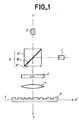
- the polarization separator element is a glass cube comprising in its median plane a superposition of thin dielectric layers 82 ensuring the reflection of a tangentially polarized wave and the transmission of a sagittally polarized wave.
- the laser source 1 emits a light beam whose polarization is such that the beam is reflected, by the polarization splitter, towards the quarter-wave plate 3.
- the beam is then transformed into a beam with circular polarization and is focused by the lens 4 on disk 5.
- the beam is reflected with a phase shift.
- the quarter-wave plate 3 then transforms the circularly polarized beam into a linearly polarized beam.
- the beam obtained is retransmitted by the separator cube 8 to the set of detectors 9 which can be, in FIG. 1, a photodetector.
- the amount of light detected by the photodetector depends on the importance of phase shift introduced by the disk 5 and including the amount of light retransmitted by the separator cube 8.
- an optical reading device comprising a laser source emitting along a determined axis a first linearly polarized beam of determined wavelength ; a beam splitter in the form of a diffraction grating receiving the first beam and retransmitting it in the form of a second beam; a focusing lens which focuses this second beam in the form of a fourth reading beam; a recording medium receiving the fourth reading beam and reflecting it in the form of a fifth beam towards the focusing lens, and the beam splitter which retransmits at least one detection beam; at least one detection device receiving the detection beam and supplying at least one electrical signal translating the detection carried out; the beam splitter inducing an astigmatism effect on the detection beam.
- the astigmatism effect is obtained by linearly varying the period of the network of rectilinear lines.
- Such a network with variable periods is of complex realization.
- the invention overcomes this drawback.
- the separator of the optical reading device is inclined relative to the determined axis (the axis of the laser source).
- the detection device is arranged on a support inclined relative to the determined axis.
- the invention is characterized in that the beam splitter has a phase network which comprises a network of grooves of elliptical shape.
- the phase network has a transparent blade with a refractive index different from the surrounding medium and carrying a network of grooves of triangular section having the shape of saw teeth, an edge of which is perpendicular to the plane of the transparent blade, the product of the height E of the edge by the difference in index n of the refraction of the transparent plate relative to the surrounding medium being substantially equal to the wavelength of the light beam.
- the beam splitter has reflection means and works in reflection vis-à-vis the beams it receives.
- the optical reading device of an optical recording medium is characterized in that the detection device comprises, in the same plane, photodetectors making it possible to adjust the focusing of the beam of reading on the support and photodetectors for the radial control of the axis determined with respect to an information track of the support and operating in push-pull mode.
- the beam splitter is a polarization splitter and it comprises a phase network comprised between a first medium and a second medium of which at least one is birefringent, the indices of the two media being equal for the linear polarization of the first beam (the linearly polarized beam emitted by the laser source).
- Figure 1 relates to an optical read head according to the known art as described above. It appears that the position of the laser source 1 and its orientation with respect to the beam splitter device 8, represented in the form of a separator cube are difficult to adjust. Likewise, the position of the photodetector 9 relative to the beam reflected by the disc 5 and therefore relative to the assembly constituted by the laser source 1, the separating cube 8 and the disc 5, must be precise. It follows that the position adjustments being made, they should no longer be susceptible to modifications due for example to reasons of thermal expansion. The housing, not shown in the figure, which contains the various elements of Figure 1, must therefore be made of material which can be machined with great precision and exhibiting almost no expansion or deformation under the effect of the temperature variation. . This is why the device in the figure leads to a relatively expensive optical disc read head.
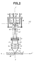
- the different elements of the optical reading device shown in FIG. 2 are aligned along the same axis YY ⁇ perpendicular to the plane of the recording medium or optical disc 5.
- FIG. 2 the optical reading device and the disc 5 have been shown in section.
- the disc information moves along an axis XX ⁇ .
- the axis YY ⁇ of the optical reading device is perpendicular to the axis XX ⁇ .
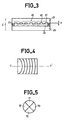
- the beam splitter 2 is produced, for example, as shown in FIG. 3.
- a transparent blade 23 made of glass for example, provided with a network 20 of grooves such as 21 and 22.
- a blade 25 also transparent, made of glass for example, determining with the blade 23 a space which is filled with a birefringent material 24 such that 'a liquid crystal.
- a seal 26 holds the liquid crystal between the two blades.
- the index of refraction of the medium constituting the plate 23 being n o , the birefringent material 24 is chosen so that for the polarization of the beam F2 which it receives, its refractive index is also n o .
- liquid crystal a eutectic mixture such as that known under the trade name E7 and manufactured by the company BDH Chemicals Ltd (United Kingdom).
- refractive index n e of birefringence is approximately 1.725. Let be an index difference between the two media 23 and 24 of 0.225.
- the depth e of the grooves 21.22 of the network 20 must be chosen equal to 1.77 ⁇ m.
- the pitch of the grooves is typically equal to 10 ⁇ m.
- the orientation of the molecules parallel to the glass slides is obtained by a conventional treatment of the rubbed polymer type.
- the liquid crystal can be replaced by any other birefringent material (e.g. oriented polymer, or polymer having a liquid crystal phase at high temperature).
- oriented polymer or polymer having a liquid crystal phase at high temperature.
- the orientation of the polymer chains, parallel to the etchings, would be obtained by passing through the nematic phase at high temperature, this orientation being preserved during cooling in the polymer phase.
- the photodetectors 6 and 7 are integrated on the same assembly or chip 16 preferably made of silicon.
- This silicon chip 16 may include a central detector not shown in the figure for regulating the power emitted by the laser source.
- the role of photodetectors 6 and 7 is to detect errors in radial and vertical positioning and to read the signal carried by the disc.
- the chip 16 and the source 1 can be assembled in the same case and pre-positioned with respect to each other.
- the lens 4 can be moved separately or integrally from the rest of the assembly to follow the radial and vertical errors.
- the laser source 1 and the elements of the chip 16 such as the photodetectors 6 and 7 are connected by electrical connections 11, 12, 13, 14 to external circuits not shown.
- the operation of the optical reading device thus described is such that a reading beam F4 is reflected by the disc 5 in the form of a beam F5.
- the beam F5 gives rise after transmission by the lens 4, the quarter-wave plate 3 and the separator 2, to two diffracted beams F8 and F8 ⁇ symmetrical with respect to the axis YY ⁇ and of the same intensity.
- These beams reach the chip 16 at the location of the detectors 6 and 7 which detect a certain amount of light.
- the beam F4 reaches the disk 5 at the location of an information signal, the beam undergoes a phase shift of its polarization. This results in a different diffraction by the polarization splitter 2. Part of the light from the beams F8 and F8 ⁇ does not reach the photodetectors 6 and 7. These then detect less light.
- the grooves 21 and 22 of the network 20 are rectilinear and parallel.
- the network then has a configuration as shown in FIG. 4 with portions of concentric ellipses, one of the axes of which is UU ⁇ .
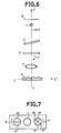
- one of the photodetectors, 7 for example, comprises four photodetectors 70, 71, 72, 73 arranged in a cross in the plane P ⁇ as shown in FIG. 5.
- the diffracted beam F8 ⁇ reaches the photodetectors 70, 71, 72 and 73 in the form of a circle and illuminates each detector equivalently.
- the beam F8 ⁇ projects on the photodetectors 70 to 73 an image of elliptical shape whose l 'one of the axes will be parallel to the axis UU ⁇ .
- the major axis of the elliptical image on the photodetectors 70 to 73 will be parallel to the axis UU ⁇ and two photodetectors, 70 and 72 for example, would receive more light than the two other photodetectors 71 and 73.
- the major axis of the image on the photodetectors will be perpendicular to the axis UU ⁇ and it is the two photodetectors 71 and 73 which will receive more light than photodetectors 70 and 72.
- the astigmatism of the network 20 can be increased by tilting the separator 2 relative to the axis YY ⁇ .
- the separator 2 is then inclined relative to the axis YY ⁇ to give the network 20 of circular shape an effect of astigmatism.
- the photodetector 6 can also include several photodetectors. In particular, it may include two photodetectors 60, 61 aligned in a direction orthogonal to the direction of travel of the information from the disc (axis XX ⁇ ).
- These photodetectors 60 and 61 are placed in such a way that, when the beam F4 is centered relative to a track of the disc 5, they both receive the same amount of light.
- the photodetectors 60 and 61 then operate in a mode called push-pull and serve to radially slave the axis YY Y of the reading device with respect to an information track of the disc 5.
- photodetectors 70 to 73 making it possible to adjust the focus of the reading beam on the disc 5, and photodetectors 60, 61 allowing a radial control of the reading beam on the disc, gives an assembly represented, in FIG. 7, in view from below.
- FIG. 7 there are on either side of the laser source 1, the four photodetectors 70 to 73 arranged in a cross and the two photodetectors 60 and 61 joined to one another.
- the beam splitter is a polarization beam splitter and in particular a separator comprising a birefringent medium.
- the system thus described also works with a beam splitter 2 which does not have a birefringent medium.
- FIG. 8 represents such an embodiment of the device of the invention.
- the beam splitter 2 consists of a transparent blade whose index of refraction (n) is different from that of the medium located on either side of the separator 2.
- the separator 2 comprises a network of grooves.
- the device of FIG. 8 does not include a quarter-wave plate. However, although this is not shown, it is possible to provide one between the separator 2 and the lens 4 for example. This quarter-wave plate will then possibly reduce the noise on the laser by avoiding sending back to the laser light of the same polarization.
- the grooves of the network of the separator 2 are, according to an exemplary embodiment, parallel rectilinear grooves.
- They can also be concentric circular grooves.
- the separator 2 is inclined relative to the axis YY ⁇ of the device as shown in figure 6.
- the separator can then have rectilinear grooves and it is inclined against the direction of diffraction to increase astigmatism. It can also have concentric circular grooves which already introduce an astigmatism, but by tilting the separator, one accentuates the astigmatism.
- the furrows can also be elliptical and the network then introduces an astigmatism like an inclined network of circular furrows.
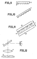
- the grooves may also have a triangular cross section. More precisely, they can also have sawtooth shapes such as that shown in FIG. 9.
- the depth e of each tooth then has a value such that one has: e. ⁇ n ⁇ ⁇ ⁇
- ⁇ n being the difference in refractive indices of the separator 2 and the medium located on either side ⁇ being the light wavelength.
- the network of grooves in the separator 2 can be reflective, for example metallized.
- FIG. 12 then represents the position of the separator in the detection device with respect to the laser source 1 and the detectors 6,7 on the one hand, and with respect to the recording medium 5 on the other hand.
- the separator 2 then works in reflection and refraction and the operation is similar to that described above.
- optical reading device thus described can be made compactly with reduced dimensions compared to known devices.
Landscapes
- Physics & Mathematics (AREA)
- Optics & Photonics (AREA)
- General Physics & Mathematics (AREA)
- Optical Head (AREA)
- Optical Recording Or Reproduction (AREA)
- Facsimile Scanning Arrangements (AREA)
- Optical Communication System (AREA)
- Holo Graphy (AREA)
- Mechanical Optical Scanning Systems (AREA)
- Supporting Of Heads In Record-Carrier Devices (AREA)
- Laser Beam Printer (AREA)
Claims (37)
- Vorrichtung zum optischen Lesen eines optischen Aufzeichnungsträgers, mit:- einer Laserquelle (1), die entlang einer vorgegebenen Achse (Y, Y') einen ersten linear polarisierten Strahl (F1) mit vorgegebener Wellenlänge (λ) aussendet;- einem Strahlteiler (2), der den ersten Strahl empfängt und ihn in Form eines zweiten Strahls (F2) überträgt;- einer Fokussierungslinse (4), die diesen zweiten Strahl in Form eines vierten Lesestrahls (F4) fokussiert;- einem Aufzeichnungsträger (5), der den vierten Lesestrahl (F4) empfängt und ihn in Form eines fünften Strahls (F5) an die Fokussierungslinse (4) und an den Strahlteiler (2) reflektiert, wobei der Strahlteiler (2) wenigstens einen Detektionsstrahl (F8, F8') überträgt;wenigstens einer Detektionsvorrichtung (6, 7), die den Detektionsstrahl (F8, F8') empfängt und wenigstens ein die ausgeführte Detektion wiedergebendes elektrisches Signal liefert;
wobei der Strahlteiler (2) ein Phasengitter mit Mitteln, die im Detektionsstrahl (F8, F8') einen Astigmatismus-Effekt bewirken, aufweist,
dadurch gekennzeichnet, daß der Teiler (2) in bezug auf die gegebene Achse (Y, Y') geneigt ist. - Vorrichtung zum optischen Lesen eines optischen Aufzeichnungsträgers, mit:- einer Laserquelle (1), die entlang einer gegebenen Achse (Y, Y') einen ersten linear polarisierten Strahl (F1) mit gegebener Wellenlänge (λ) aussendet;- einem Strahlteiler (2), der den ersten Strahl empfängt und ihn in Form eines zweiten Strahls (F2) überträgt;- einer Fokussierungslinse (4), die diesen zweiten Strahl (F2) in Form eines vierten Lesestrahls (F4) fokussiert;- einem Aufzeichnungsträger (5), der den vierten Lesestrahl (F4) empfängt und ihn in Form eines fünften Strahls (F5) an die Fokussierungslinse (4) und an den Strahlteiler (2) überträgt, wobei der Strahlteiler (2) wenigstens einen Detektionsstrahl (F8, F8') überträgt;- wenigstens einer Detektionsvorrichtung (6, 7), die den Detektionsstrahl (F8, F8') empfängt und wenigstens ein die ausgeführte Detektion wiedergebendes elektrisches Signal liefert;wobei der Strahlteiler (2) ein Phasengitter mit Mitteln, die im Detektionsstrahl einen Astigmatismus-Effekt bewirken, aufweist,
dadurch gekennzeichnet, daß das Phasengitter ein Gitter aus elliptisch geformten Rillen aufweist. - Vorrichtung gemäß Anspruch 1 oder 2, dadurch gekennzeichnet, daß das Phasengitter ein durchsichtiges Plättchen mit einem vom umgebenden Medium verschiedenen Brechungsindex (n) aufweist und ein Rillengitter trägt.
- Vorrichtung gemäß den Ansprüchen 1 und 3, dadurch gekennzeichnet, daß das Rillengitter ein Gitter von geraden Rillen ist.
- Vorrichtung gemäß den Ansprüchen 1 und 3, dadurch gekennzeichnet, daß das Rillengitter ein Gitter von kreisförmigen, konzentrischen Rillen ist.
- Vorrichtung gemäß den Ansprüchen 1 und 3, dadurch gekennzeichnet, daß die Rillen einen rechtwinkligen Querschnitt besitzen.
- Vorrichtung gemäß Anspruch 1, dadurch gekennzeichnet, daß der Sinn der Neigung des Teilers in bezug auf die Richtung des Detektionsstrahls entgegengesetzt zu dem der Beugung ist.
- Vorrichtung zum optischen Lesen eines optischen Aufzeichnungsträgers, mit:- einer Laserquelle (1), die entlang einer gegebenen Achse (Y, Y') einen ersten linear polarisierten Strahl (F1) mit gegebener Wellenlänge (λ) aussendet;- einem Strahlteiler (2), der den ersten Strahl empfängt und ihn in Form eines zweiten Strahls (F2) überträgt;- einer Fokussierungslinse (4), die diesen zweiten Strahl (F2) in Form eines vierten Lesestrahls (F4) fokussiert;- einem Aufzeichnungsträger (5), der den vierten Laserstrahl (F4) empfängt und ihn in Form eines fünften Strahls (F5) auf die Fokussierungslinse (4) und den Strahlteiler (2) reflektiert, wobei der Strahlteiler (2) wenigstens einen Detektionsstrahl (F8, F8') überträgt;- wenigstens einer Detektionsvorrichtung (6, 7), die den Detektionsstrahl (F8, F8') empfängt und wenigstens ein die ausgeführte Detektion wiedergebendes elektrisches Signal liefert;wobei der Strahlteiler (2) ein Phasengitter mit Mitteln, die im Detektionsstrahl (F8, F8') einen Astigmatismus-Effekt bewirken, umfaßt,
dadurch gekennzeichnet, daß das Phasengitter ein durchsichtiges Plättchen mit einem vom umgebenden Medium verschiedenen Brechungsindex (n) aufweist und ein Gitter mit Rillen von dreieckigem Querschnitt, die die Form von Sägezähnen besitzen, von denen eine Kante senkrecht zur Ebene des durchsichtigen Plättchens orientiert ist, trägt, wobei das Produkt aus der Höhe (e) der Kante und der Differenz der Brechungsindizes (n) der Brechung des durchsichtigen Plättchens bezüglich des umgebenden Mediums im wesentlichen gleich der Wellenlänge des Lichtstrahls ist. - Vorrichtung zum optischen Lesen eines optischen Aufzeichnungsträgers, mit:- einer Laserquelle (1), die entlang einer gegebenen Achse (Y, Y') einen linear polarisierten ersten Strahl (F1) mit gegebener Wellenlänge (λ) aussendet;- einem Strahlteiler (2), der den ersten Strahl empfängt und ihn in Form eines zweiten Strahls (F2) überträgt;- einer Fokussierungslinse (4), die diesen zweiten Strahl (F2) in Form eines vierten Lesestrahls (F4) fokussiert;- einem Aufzeichnungsträger (5), der den vierten Lesestrahl (F4) empfängt und ihn in Form eines fünften Strahls (F5) auf die Fokussierungslinse (4) und den Strahlteiler (2) reflektiert, wobei der Strahlteiler (2) wenigstens einen Detektionsstrahl (F8, F8') überträgt;- wenigstens einer Detektionsvorrichtung (6, 7), die den Detektionsstrahl (F8, F8') empfängt und wenigstens ein die ausgeführte Detektion wiedergebendes elektrisches Signal liefert;wobei der Strahlteiler (2) ein Phasengitter mit Mitteln, die im Detektionsstrahl (F8, F8') einen Astigmatismus-Effekt bewirken, umfaßt,
dadurch gekennzeichnet, daß der Strahlteiler (2) Reflexionsmittel besitzt und gegenüber den Strahlen, die er empfängt, in Reflexion arbeitet. - Vorrichtung gemäß einem der vorangehenden Ansprüche, dadurch gekennzeichnet, daß zwischen dem Strahlteiler (2) und der Fokussierungslinse ein 1/4-Wellenlängen-Plättchen angeordnet ist.
- Vorrichtung zum optischen Lesen eines optischen Aufzeichnungsträgers, mit:- einer Laserquelle (1), die entlang einer gegebenen Achse (Y, Y') einen linear polarisierten ersten Strahl (F1) mit gegebener Wellenlänge (λ) aussendet;- einem Strahlteiler (2), der den ersten Strahl empfängt und ihn in Form eines zweiten Strahls (F2) überträgt;- einer Fokussierungslinse (4), die diesen zweiten Strahl (F2) in Form eines vierten Lesestrahls (F4) fokussiert;- einem Aufzeichnungsträger (5), der den vierten Lesestrahl (F4) empfängt und ihn in Form eines fünften Strahls (F5) auf die Fokussierungslinse (4) und den Strahlteiler (2) reflektiert, wobei der Strahlteiler (2) wenigstens einen Detektionsstrahl (F8, F8') überträgt;- wenigstens einer Detektionsvorrichtung (6, 7), die den Detektionsstrahl (F8, F8') empfängt und wenigstens ein die ausgeführte Detektion wiedergebendes elektrisches Signal liefert;wobei der Strahlteiler (2) ein Phasengitter mit Mitteln, die im Detektionsstrahl (F8, F8') einen Astigmatismus-Effekt bewirken, umfaßt,
dadurch gekennzeichnet, daß die Detektionsvorrichtung (6, 7) auf einem Träger (16) angeordnet ist, der in bezug auf die gegebene Achse (Y, Y') geneigt ist. - Vorrichtung zum optischen Lesen eines optischen Aufzeichnungsträgers, mit:- einer Laserquelle (1), die entlang einer gegebenen Achse (Y, Y') einen linear polarisierten ersten Strahl (F1) mit gegebener Wellenlänge (λ) aussendet;- einem Strahlteiler (2), der den ersten Strahl empfängt und ihn in Form eines zweiten Strahls (F2) überträgt;- einer Fokussierungslinse (4), die diesen zweiten Strahl (F2) in Form eines vierten Lesestrahls (F4) fokussiert;- einem Aufzeichnungsträger (5), der den vierten Lesestrahl (F4) empfängt und ihn in Form eines fünften Strahls (F5) auf die Fokussierungslinse (4) und den Strahlteiler (2) reflektiert, wobei der Strahlteiler (2) wenigstens einen Detektionsstrahl (F8, F8') überträgt;- wenigstens einer Detektionsvorrichtung (6, 7), die den Detektionsstrahl (F8, F8') empfängt und wenigstens ein die ausgeführte Detektion wiedergebendes elektrisches Signal liefert;wobei der Strahlteiler (2) ein Phasengitter mit Mitteln, die im Detektionsstrahl (F8, F8') einen Astigmatismus-Effekt bewirken, um festzustellen, ob der vierte Strahl (F4) auf dem Träger (5) richtig fokussiert ist, umfaßt,
dadurch gekennzeichnet, daß die Detektionsvorrichtung (6, 7) in derselben Ebene Photodetektoren (70 bis 73), die die Fokussierung des Lesestrahls auf dem Träger (5) einzustellen erlauben, und im Gegentakt-Modus arbeitende Photodetektoren (60, 61) zum radialen Einstellen der gegebenen Achse (Y, Y') in bezug auf eine Informationsspur des Trägers (5) umfaßt. - Vorrichtung gemäß Anspruch 12, dadurch gekennzeichnet, daß die Detektoren (70 bis 73; 60, 61) zum Einstellen der Fokussierung und zur radialen Einstellung die auf den Träger (5) eingeschriebenen Informationen zu erfassen erlauben.
- Vorrichtung zum optischen Lesen eines optischen Aufzeichnungsträgers, mit:- einer Laserquelle (1), die entlang einer gegebenen Achse (Y, Y') einen linear polarisierten ersten Strahl (F1) mit gegebener Wellenlänge (λ) aussendet;- einem Strahlteiler (2), der den ersten Strahl empfängt und ihn in Form eines zweiten Strahls (F2) überträgt;- einer Fokussierungslinse (4), die diesen zweiten Strahl (F2) in Form eines vierten Lesestrahls (F4) fokussiert;- einem Aufzeichnungsträger (5), der den vierten Lesestrahl (F4) empfängt und ihn in Form eines fünften Strahls (F5) auf die Fokussierungslinse (4) und in Form eines sechsten Strahls (F6) auf den Strahlteiler (2) reflektiert, wobei der Strahlteiler (2) wenigstens einen Detektionsstrahl (F8, F8') überträgt;- wenigstens einer Detektionsvorrichtung (6, 7), die den Detektionsstrahl (F8, F8') empfängt und wenigstens ein die ausgeführte Detektion wiedergebendes elektrisches Signal liefert;dadurch gekennzeichnet, daß der Polarisations-Strahlteiler (2) ein Phasengitter (20) aufweist, das zwischen einem ersten Medium (23) und einem zweiten Medium (24) enthalten ist, von denen wenigstens eines doppelbrechend ist, wobei die Indizes der zwei Medien in bezug auf die lineare Polarisation des ersten Strahls (F1) gleich sind.
- Vorrichtung zum optischen Lesen gemäß Anspruch 14, dadurch gekennzeichnet, daß der Strahlteiler umfaßt:- ein durchsichtiges starres Plättchen (23) mit einem ersten Brechungsindex (n0), das ein als Phasengitter dienendes Rillengitter (20) trägt;- ein doppelbrechendes Material (24), das am Rillengitter (20) angebracht ist und die Rillen dieses Gitters auffüllt, wobei der Brechungsindex dieses doppelbrechenden Materials (24) einen ersten Wert, der gleich einem ersten Index (no) des durchsichtigen starren Plättchens (23) für die Polarisation des zweiten Strahls (F2) ist, und einen zweiten Doppelbrechungsindex-Wert (ne) für die Polarisation des sechsten Strahls (F6) besitzt;- ein durchsichtiges Plättchen (25), um das doppelbrechende Material (24) gegen das durchsichtige starre Plättchen (23) zu halten.
- Vorrichtung zum optischen Lesen gemäß Anspruch 15, dadurch gekennzeichnet, daß das durchsichtige starre Plättchen (23) aus Glas ist.
- Vorrichtung zum optischen Lesen gemäß Anspruch 15, dadurch gekennzeichnet, daß das durchsichtige starre Plättchen (23) ein Polymer-Material ist.
- Vorrichtung zum optischen Lesen gemäß Anspruch 15, dadurch gekennzeichnet, daß das doppelbrechende Material (24) ein Flüssigkristall ist, dessen Molekülachse parallel zu den Rillen des Gitters (20) des durchsichtigen starren Plättchens (23) ist.
- Vorrichtung zum optischen Lesen gemäß Anspruch 15, dadurch gekennzeichnet, daß das dopppelbrechende Material (24) ein Polymer-Material ist, bei dem die Ausrichtung der Moleküle durch Reiben des Polymer-Materials (24) erhalten wird.
- Vorrichtung zum optischen Lesen gemäß Anspruch 15, dadurch gekennzeichnet, daß das doppelbrechende Material (24) ein Polymer-Material ist, das bei hoher Temperatur eine nematische Flüssigkristallphase aufweist, die bei der Abkühlung in die Polymerphase erhalten bleibt.
- Vorrichtung zum optischen Lesen gemäß Anspruch 15, dadurch gekennzeichnet, daß die Tiefe (e) der Rillen proportional zur halben Wellenlänge der Emission der Laserquelle (1) und umgekehrt proportional zur Differenz der Indizes der durchsichtigen starren Platte und des doppelbrechenden Materials ist.
- Vorrichtung zum optischen Lesen gemäß Anspruch 15, in der der Aufzeichnungsträger in einer Ebene (P) angeordnet ist, dadurch gekennzeichnet, daß der erste Strahl (F1) senkrecht zur Ebene des Aufzeichnungsträgers (5) orientiert ist und daß sich der Strahlteiler (2) in der Bahn dieses Strahls (F1) befindet.
- Vorrichtung zum optischen Lesen gemäß Anspruch 15, dadurch gekennzeichnet, daß die Rillen (20) des durchsichtigen Plättchens (23) geradlinig und parallel sind.
- Vorrichtung zum optischen Lesen gemäß Anspruch 15, dadurch gekennzeichnet, daß die Rillen (20) gebogen sind.
- Vorrichtung zum optischen Lesen gemäß Anspruch 24, dadurch gekennzeichnet, daß die Rillen Abschnitte konzentrischer Kreise sind.
- Vorrichtung zum optischen Lesen gemäß Anspruch 25, dadurch gekennzeichnet, daß die Rillen (20) Abschnitte konzentrischer Ellipsen sind.
- Vorrichtung zum optischen Lesen gemäß Anspruch 14, dadurch gekennzeichnet, daß das Phasengitter (20) eben ist.
- Vorrichtung zum optischen Lesen gemäß Anspruch 14, dadurch gekennzeichnet, daß das Phasengitter (20) senkrecht zur Achse (Y, Y') des ersten Strahls (F1) orientiert ist.
- Vorrichtung zum optischen Lesen gemäß Anspruch 14, dadurch gekennzeichnet, daß das Phasengitter (20) in bezug auf die Achse (Y, Y') des ersten Strahls (F1) geneigt ist.
- Vorrichtung zum optischen Lesen gemäß Anspruch 14, dadurch gekennzeichnet, daß die Detektionsvorrichtung (6, 7) in der Nähe der Quelle (1) in einer zum Aufzeichnungsträger nicht konjugierten Ebene in der Bahn des Detektionsstrahls (F8, F8') angeordnet ist.
- Vorrichtung zum optischen Lesen gemäß Anspruch 22, dadurch gekennzeichnet, daß die Detektionsvorrichtung im wesentlichen entlang der Achse (Y, Y') des ersten Strahls (F1) angeordnet ist.
- Vorrichtung zum optischen Lesen gemäß Anspruch 14, dadurch gekennzeichnet, daß die Detektionsvorrichtung eine Mehrzahl von Lichtdetektoren (6, 7) umfaßt.
- Vorrichtung zum optischen Lesen gemäß Anspruch 32, in der sich der Aufzeichnungsträger entlang einer Richtung (X, X') verschiebt, dadurch gekennzeichnet, daß die Detektionsvorrichtung wenigstens zwei Detektoren aufweist, die in einer zur Ebene (P) des Aufzeichnungsträgers (5) parallelen Ebene (P') in einer zur Verschiebungsrichtung (X, X') des Aufzeichnungsträgers (5) senkrechten Richtung angeordnet sind.
- Vorrichtung zum optischen Lesen gemäß Anspruch 32, in der sich der Aufzeichnungsträger in einer Richtung (X, X') verschiebt, dadurch gekennzeichnet, daß die Detektionsvorrichtung wenigstens zwei Detektoren aufweist, die in einer zur Ebene (P) des Aufzeichnungsträgers (5) parallelen Ebene in einer zur Verschiebungsrichtung (X, X') des Aufzeichnungsträgers (5) parallelen Richtung angeordnet sind.
- Vorrichtung zum optischen Lesen gemäß Anspruch 33, dadurch gekennzeichnet, daß die Detektionsvorrichtung außerdem zwei Detektoren aufweist, die in einer zur Verschiebungsrichtung (X, X') des Aufzeichnungsträgers parallelen Richtung angeordnet sind.
- Vorrichtung zum optischen Lesen gemäß Anspruch 14, dadurch gekennzeichnet, daß der Aufzeichnungsträger eine optische Platte ist.
- Vorrichtung zum optischen Lesen gemäß Anspruch 14, dadurch gekennzeichnet, daß der Strahlteiler ein ebenes Reflexionsmittel aufweist, das dem ersten Medium (23) zugehört.
Priority Applications (1)
| Application Number | Priority Date | Filing Date | Title |
|---|---|---|---|
| AT87400773T ATE66762T1 (de) | 1986-04-11 | 1987-04-07 | Optische leseeinrichtung fuer optische aufnahmetraeger. |
Applications Claiming Priority (2)
| Application Number | Priority Date | Filing Date | Title |
|---|---|---|---|
| FR8605239 | 1986-04-11 | ||
| FR8605239A FR2597249B1 (fr) | 1986-04-11 | 1986-04-11 | Dispositif de lecture optique de support d'enregistrement optique |
Publications (2)
| Publication Number | Publication Date |
|---|---|
| EP0241372A1 EP0241372A1 (de) | 1987-10-14 |
| EP0241372B1 true EP0241372B1 (de) | 1991-08-28 |
Family
ID=9334165
Family Applications (1)
| Application Number | Title | Priority Date | Filing Date |
|---|---|---|---|
| EP87400773A Expired - Lifetime EP0241372B1 (de) | 1986-04-11 | 1987-04-07 | Optische Leseeinrichtung für optische Aufnahmeträger |
Country Status (11)
| Country | Link |
|---|---|
| US (1) | US5168485A (de) |
| EP (1) | EP0241372B1 (de) |
| JP (3) | JP2589337B2 (de) |
| KR (1) | KR100235125B1 (de) |
| AT (1) | ATE66762T1 (de) |
| AU (1) | AU7167587A (de) |
| CA (1) | CA1301319C (de) |
| DE (1) | DE3772426D1 (de) |
| ES (1) | ES2024528B3 (de) |
| FR (1) | FR2597249B1 (de) |
| WO (1) | WO1987006386A1 (de) |
Families Citing this family (30)
| Publication number | Priority date | Publication date | Assignee | Title |
|---|---|---|---|---|
| NL8502835A (nl) * | 1985-10-17 | 1987-05-18 | Philips Nv | Inrichting voor het met optische straling aftasten van een informatievlak. |
| US4794585A (en) * | 1986-05-06 | 1988-12-27 | Lee Wai Hon | Optical head having a hologram lens and polarizers for use with magneto-optic medium |
| EP0348221B1 (de) * | 1988-06-23 | 1994-12-14 | Sharp Kabushiki Kaisha | Optische Abtastvorrichtung |
| EP0390445A3 (de) * | 1989-03-27 | 1992-01-22 | Matsushita Electric Industrial Co., Ltd. | Optischer Abtastkopf |
| US5085496A (en) * | 1989-03-31 | 1992-02-04 | Sharp Kabushiki Kaisha | Optical element and optical pickup device comprising it |
| FR2646245B1 (fr) * | 1989-04-25 | 1991-06-14 | Thomson Csf | Dispositif de lecture optique pour support d'enregistrement optique |
| US5050153A (en) * | 1989-06-06 | 1991-09-17 | Wai-Hon Lee | Semiconductor laser optical head assembly |
| EP0405444B1 (de) * | 1989-06-26 | 1997-09-03 | Nec Corporation | Optisches System |
| JP2616018B2 (ja) * | 1989-06-26 | 1997-06-04 | 日本電気株式会社 | 光ヘッド装置 |
| EP0459790B1 (de) * | 1990-05-31 | 1996-04-17 | Mitsubishi Denki Kabushiki Kaisha | Optisches Aufzeichnungs- und Wiedergabegerät |
| JP2894808B2 (ja) * | 1990-07-09 | 1999-05-24 | 旭光学工業株式会社 | 偏光を有する光学系 |
| US5581523A (en) * | 1992-11-17 | 1996-12-03 | Seiko Epson Corporation | Laser emission unit, optical head and optical memory device |
| JP3362896B2 (ja) * | 1993-01-25 | 2003-01-07 | ソニー株式会社 | 光ピックアップ及び光ディスク装置 |
| US5757754A (en) * | 1994-06-30 | 1998-05-26 | Matsushita Electric Industrial Co., Ltd. | Holographic optical head |
| FR2723243B1 (fr) * | 1994-07-26 | 1996-09-06 | Thomson Csf | Dispositif d'enregistrement et/ou de lecture de tetes magnetiques et son procede de realisation |
| US6026065A (en) * | 1995-03-04 | 2000-02-15 | Lg Electronics Inc. | Optical pick-up apparatus capable of reading data irrespective of disc type |
| WO1997013245A1 (fr) | 1995-10-03 | 1997-04-10 | Asahi Glass Company Ltd. | Dispositif tete optique et procede de fabrication associe |
| US6618116B1 (en) | 1997-10-02 | 2003-09-09 | Asahi Glass Company, Limited | Optical head device and a diffraction element suitable for the device, and a method of manufacturing the diffraction element and the optical head device |
| FR2786345B1 (fr) | 1998-11-24 | 2001-02-09 | Thomson Csf | Dispositif de cryptage quantique |
| US6584059B1 (en) * | 1999-02-17 | 2003-06-24 | Matsushita Electric Industrial Co., Ltd. | Information recording and reproducing apparatus |
| US7149173B2 (en) * | 2000-10-17 | 2006-12-12 | Thales | Medium for recording optically readable data, method for making same and optical system reproducing said data |
| JP2002250809A (ja) * | 2001-02-26 | 2002-09-06 | Alps Electric Co Ltd | 光学部材およびそれを用いた光ピックアップ |
| FR2824905B1 (fr) * | 2001-05-15 | 2003-08-29 | Thomson Csf | Gyrometre a fibre optique |
| FR2837972B1 (fr) | 2002-04-02 | 2006-07-21 | Thales Sa | Procede d'asservissement radial pour un dispositif de reproduction d'informations d'un disque optique et dispositif de reproduction mettant en oeuvre ce procede |
| JP4106981B2 (ja) * | 2002-06-28 | 2008-06-25 | 旭硝子株式会社 | 光減衰器 |
| CN1774750A (zh) * | 2003-04-14 | 2006-05-17 | 皇家飞利浦电子股份有限公司 | 光学扫描设备 |
| US9938844B2 (en) | 2011-10-26 | 2018-04-10 | General Electric Company | Metallic stator seal |
| US10161523B2 (en) | 2011-12-23 | 2018-12-25 | General Electric Company | Enhanced cloth seal |
| US9551569B2 (en) * | 2014-10-13 | 2017-01-24 | Hermes-Epitek Corporation | Apparatus and method for curvature and thin film stress measurement |
| US11269193B2 (en) * | 2017-11-27 | 2022-03-08 | Liqxtal Technology Inc. | Optical sensing device and structured light projector |
Family Cites Families (18)
| Publication number | Priority date | Publication date | Assignee | Title |
|---|---|---|---|---|
| JPS51100628A (de) * | 1975-03-03 | 1976-09-06 | Hitachi Ltd | |
| NL7907216A (nl) * | 1979-09-28 | 1981-03-31 | Philips Nv | Optisch fokusfout-detektiestelsel. |
| JPS6213Y2 (de) * | 1981-03-20 | 1987-01-06 | ||
| JPS58130148A (ja) * | 1982-01-28 | 1983-08-03 | 三重県 | 額縁等の立体的装飾成形体用成形材料ならびにそれを用いた成形方法 |
| JPS59119548A (ja) * | 1982-12-25 | 1984-07-10 | Pioneer Electronic Corp | 光学式ピツクアツプ装置 |
| JP2539350B2 (ja) * | 1983-12-16 | 1996-10-02 | 株式会社日立製作所 | 光ヘツド装置 |
| JPH069089B2 (ja) * | 1985-04-05 | 1994-02-02 | 日本電気株式会社 | 光ヘツド |
| JPS61178740A (ja) * | 1985-02-05 | 1986-08-11 | Canon Inc | 光ヘツド装置 |
| US4733065A (en) * | 1984-06-27 | 1988-03-22 | Canon Kabushiki Kaisha | Optical head device with diffraction grating for separating a light beam incident on an optical recording medium from a light beam reflected therefrom |
| CA1257392A (en) * | 1985-03-20 | 1989-07-11 | Masayuki Kato | Optical pickup with hologram lenses |
| JPS6226654A (ja) * | 1985-07-26 | 1987-02-04 | Nec Corp | 光ヘツド |
| NL8502835A (nl) * | 1985-10-17 | 1987-05-18 | Philips Nv | Inrichting voor het met optische straling aftasten van een informatievlak. |
| JPS62139146A (ja) * | 1985-12-12 | 1987-06-22 | Nec Corp | 光ヘツド装置 |
| DE3679648D1 (de) * | 1985-12-10 | 1991-07-11 | Nec Corp | Optischer kopf mit einem beugungsgitter zum richten von zwei oder mehreren gebeugten lichtstrahlen auf optische detektoren. |
| JPH0630164B2 (ja) * | 1985-12-16 | 1994-04-20 | キヤノン株式会社 | 光ヘツド装置 |
| NL8601974A (nl) * | 1986-08-01 | 1988-03-01 | Philips Nv | Inrichting voor het met optische straling aftasten van een stralingsreflekterend informatievlak. |
| JPH0514334Y2 (de) * | 1986-10-01 | 1993-04-16 | ||
| JPH0777038B2 (ja) * | 1986-12-25 | 1995-08-16 | ソニー株式会社 | 光学ピツクアツプ装置 |
-
1986
- 1986-04-11 FR FR8605239A patent/FR2597249B1/fr not_active Expired
-
1987
- 1987-03-31 AU AU71675/87A patent/AU7167587A/en not_active Abandoned
- 1987-03-31 WO PCT/FR1987/000102 patent/WO1987006386A1/fr not_active Ceased
- 1987-03-31 JP JP62502219A patent/JP2589337B2/ja not_active Expired - Lifetime
- 1987-03-31 KR KR1019870701164A patent/KR100235125B1/ko not_active Expired - Lifetime
- 1987-04-07 ES ES87400773T patent/ES2024528B3/es not_active Expired - Lifetime
- 1987-04-07 EP EP87400773A patent/EP0241372B1/de not_active Expired - Lifetime
- 1987-04-07 DE DE8787400773T patent/DE3772426D1/de not_active Expired - Lifetime
- 1987-04-07 AT AT87400773T patent/ATE66762T1/de active
- 1987-04-09 CA CA000534212A patent/CA1301319C/fr not_active Expired - Lifetime
-
1991
- 1991-07-17 US US07/731,428 patent/US5168485A/en not_active Expired - Lifetime
-
1996
- 1996-07-08 JP JP8178194A patent/JP2935418B2/ja not_active Expired - Lifetime
-
1998
- 1998-01-08 JP JP10002532A patent/JPH10188336A/ja active Pending
Also Published As
| Publication number | Publication date |
|---|---|
| EP0241372A1 (de) | 1987-10-14 |
| WO1987006386A1 (fr) | 1987-10-22 |
| KR880701438A (ko) | 1988-07-27 |
| DE3772426D1 (de) | 1991-10-02 |
| ATE66762T1 (de) | 1991-09-15 |
| FR2597249A1 (fr) | 1987-10-16 |
| JPH0922541A (ja) | 1997-01-21 |
| ES2024528B3 (es) | 1992-03-01 |
| AU7167587A (en) | 1987-11-09 |
| JPS63503102A (ja) | 1988-11-10 |
| FR2597249B1 (fr) | 1988-06-17 |
| JP2589337B2 (ja) | 1997-03-12 |
| KR100235125B1 (ko) | 1999-12-15 |
| US5168485A (en) | 1992-12-01 |
| JP2935418B2 (ja) | 1999-08-16 |
| JPH10188336A (ja) | 1998-07-21 |
| CA1301319C (fr) | 1992-05-19 |
Similar Documents
| Publication | Publication Date | Title |
|---|---|---|
| EP0241372B1 (de) | Optische Leseeinrichtung für optische Aufnahmeträger | |
| EP0029755B1 (de) | Stigmatische optische Emitter/Empfänger-Vorrichtung für kohärente Strahlung und optischer Schreib/Lesekopf mit einer solchen Vorrichtung | |
| EP0088671B1 (de) | Optischer Kopf in einer Schreib-Lese-Einrichtung für einen Informationsträger | |
| FR2566953A1 (fr) | Dispositif de tete optique | |
| FR2523351A1 (fr) | Tete optique dans un dispositif d'enregistrement-lecture d'un support d'information | |
| US6810001B2 (en) | Optical pickup apparatus and optical pickup method adapted for selectively using laser light of different wavelengths | |
| FR2498340A1 (fr) | Procede et appareil de detection d'un signal d'erreur de focalisation d'un objectif | |
| EP0423295B1 (de) | Optische leseeinrichtung für einen optischen aufzeichnungsträger | |
| FR2601173A1 (fr) | Tete de lecture optique pour disques numeriques. | |
| EP0022682B1 (de) | Optischer Lesekopf mit Halbleiter-Laserquelle und eine mit optischer Reflexion arbeitende Lesevorrichtung zum Lesen eines Informationsträgers, die einen solchen optischen Lesekopf enthält | |
| KR19990019448A (ko) | 기록 및 재생가능형 디스크를 위한 광픽업 | |
| EP0375492B1 (de) | Optische Vorrichtung für das Beobachten eines ausgedehnten Objektes | |
| FR2738384A1 (fr) | Systeme de lecture optique a focalisation multiple pour reproduire des informations enregistrees sur des disques optiques | |
| EP0057339B1 (de) | Optischer Fokussierungsfehlerdetektor und damit ausgerüsteter optischer Aufnehmer-Leser | |
| FR2739965A1 (fr) | Dispositif emetteur-recepteur de lumiere et systeme de lecture optique | |
| EP0522926B1 (de) | Lesesystem für optische Platte | |
| KR100565036B1 (ko) | 호환형 광픽업장치 | |
| FR2661542A1 (fr) | Appareil optique de lecture de donnees sur un disque. | |
| KR100480638B1 (ko) | 광픽업장치 | |
| KR0181815B1 (ko) | 듀얼 포커스 광 픽-업장치 | |
| KR19990049998A (ko) | 광량조절형 액정판 듀얼 포커스 광픽업장치 | |
| KR100421012B1 (ko) | 홀로그램이 형성된 빔스프리터를 구비한 광픽업장치와이를 이용한 광축보정방법 | |
| KR100403596B1 (ko) | 직각삼각형 모양의 빔스프리터를 구비한 광픽업장치와이를 이용한 광축보정방법 | |
| JPS61233442A (ja) | 光ヘツド装置 | |
| JP2006505090A (ja) | 光走査デバイス |
Legal Events
| Date | Code | Title | Description |
|---|---|---|---|
| PUAI | Public reference made under article 153(3) epc to a published international application that has entered the european phase |
Free format text: ORIGINAL CODE: 0009012 |
|
| AK | Designated contracting states |
Kind code of ref document: A1 Designated state(s): AT BE CH DE ES FR GB IT LI LU NL SE |
|
| 17P | Request for examination filed |
Effective date: 19871104 |
|
| 17Q | First examination report despatched |
Effective date: 19890705 |
|
| GRAA | (expected) grant |
Free format text: ORIGINAL CODE: 0009210 |
|
| RAP1 | Party data changed (applicant data changed or rights of an application transferred) |
Owner name: THOMSON S.A. |
|
| AK | Designated contracting states |
Kind code of ref document: B1 Designated state(s): AT BE CH DE ES FR GB IT LI LU NL SE |
|
| PG25 | Lapsed in a contracting state [announced via postgrant information from national office to epo] |
Ref country code: SE Effective date: 19910828 Ref country code: AT Effective date: 19910828 |
|
| REF | Corresponds to: |
Ref document number: 66762 Country of ref document: AT Date of ref document: 19910915 Kind code of ref document: T |
|
| ITF | It: translation for a ep patent filed | ||
| GBT | Gb: translation of ep patent filed (gb section 77(6)(a)/1977) | ||
| REF | Corresponds to: |
Ref document number: 3772426 Country of ref document: DE Date of ref document: 19911002 |
|
| REG | Reference to a national code |
Ref country code: ES Ref legal event code: FG2A Ref document number: 2024528 Country of ref document: ES Kind code of ref document: B3 |
|
| PLBE | No opposition filed within time limit |
Free format text: ORIGINAL CODE: 0009261 |
|
| STAA | Information on the status of an ep patent application or granted ep patent |
Free format text: STATUS: NO OPPOSITION FILED WITHIN TIME LIMIT |
|
| 26N | No opposition filed | ||
| EPTA | Lu: last paid annual fee | ||
| REG | Reference to a national code |
Ref country code: GB Ref legal event code: IF02 |
|
| PGFP | Annual fee paid to national office [announced via postgrant information from national office to epo] |
Ref country code: DE Payment date: 20060330 Year of fee payment: 20 |
|
| PGFP | Annual fee paid to national office [announced via postgrant information from national office to epo] |
Ref country code: NL Payment date: 20060403 Year of fee payment: 20 |
|
| PGFP | Annual fee paid to national office [announced via postgrant information from national office to epo] |
Ref country code: GB Payment date: 20060405 Year of fee payment: 20 |
|
| PGFP | Annual fee paid to national office [announced via postgrant information from national office to epo] |
Ref country code: FR Payment date: 20060410 Year of fee payment: 20 |
|
| PGFP | Annual fee paid to national office [announced via postgrant information from national office to epo] |
Ref country code: CH Payment date: 20060413 Year of fee payment: 20 |
|
| PGFP | Annual fee paid to national office [announced via postgrant information from national office to epo] |
Ref country code: LU Payment date: 20060420 Year of fee payment: 20 |
|
| PGFP | Annual fee paid to national office [announced via postgrant information from national office to epo] |
Ref country code: IT Payment date: 20060430 Year of fee payment: 20 |
|
| PGFP | Annual fee paid to national office [announced via postgrant information from national office to epo] |
Ref country code: ES Payment date: 20060523 Year of fee payment: 20 |
|
| PGFP | Annual fee paid to national office [announced via postgrant information from national office to epo] |
Ref country code: BE Payment date: 20060614 Year of fee payment: 20 |
|
| PG25 | Lapsed in a contracting state [announced via postgrant information from national office to epo] |
Ref country code: NL Free format text: LAPSE BECAUSE OF EXPIRATION OF PROTECTION Effective date: 20070407 |
|
| PG25 | Lapsed in a contracting state [announced via postgrant information from national office to epo] |
Ref country code: ES Free format text: LAPSE BECAUSE OF EXPIRATION OF PROTECTION Effective date: 20070409 |
|
| REG | Reference to a national code |
Ref country code: CH Ref legal event code: PL |
|
| REG | Reference to a national code |
Ref country code: GB Ref legal event code: PE20 |
|
| NLV7 | Nl: ceased due to reaching the maximum lifetime of a patent |
Effective date: 20070407 |
|
| REG | Reference to a national code |
Ref country code: ES Ref legal event code: FD2A Effective date: 20070409 |
|
| PG25 | Lapsed in a contracting state [announced via postgrant information from national office to epo] |
Ref country code: GB Free format text: LAPSE BECAUSE OF EXPIRATION OF PROTECTION Effective date: 20070406 |
|
| BE20 | Be: patent expired |
Owner name: S.A. *THOMSON Effective date: 20070407 |